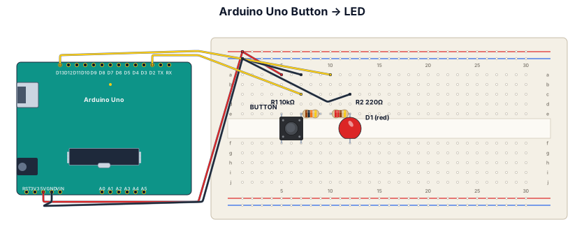
아두이노 우노로 버튼 누르면 LED 켜지는 회로: D2에 풀다운 저항이 있는 버튼, D13에 220옴 저항이 있는 LED
NODE ARCHIVE · REAL DIAGRAM BRIEFS
Diagram Examples from Real Visitor Prompts
Browse eligible diagrams shared by FreeDiagram visitors, inspect the exact prompts, and build your own version.
Browse 99 real creationsCOMMUNITY OUTPUTS · EXACT PROMPTS
Breadboard Wiring
Showing 1–9 of 9. No stock examples or system defaults. Choose a tool, study a real result, then reopen its prompt as your starting point.
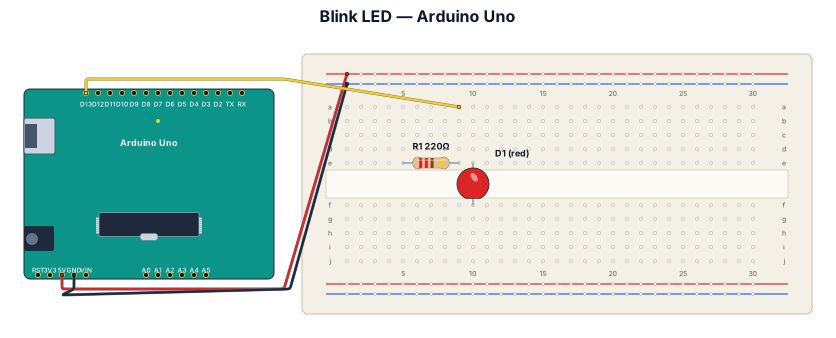
아두이노 우노로 220옴 저항과 LED 깜빡이기 (헬로월드)
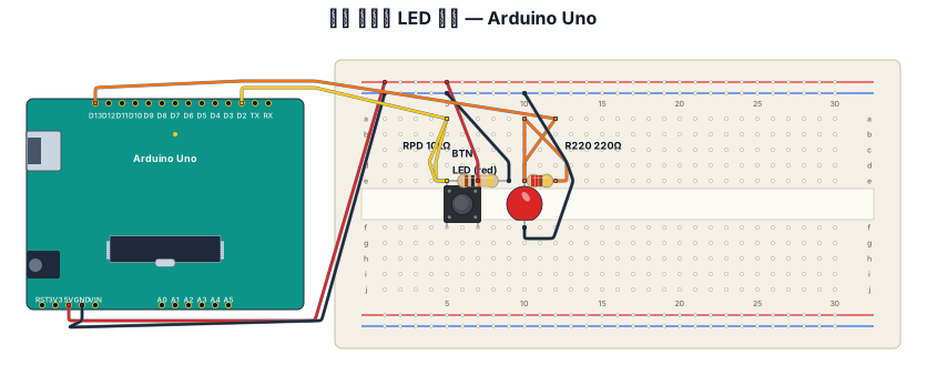
아두이노 우노로 버튼 누르면 LED 켜지는 회로: D2에 풀다운 저항이 있는 버튼, D13에 220옴 저항이 있는 LED
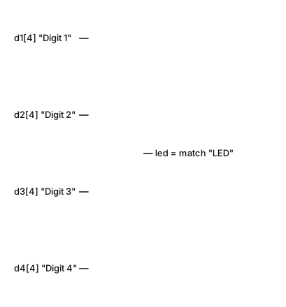
도어락같이 정해진 4자리 숫자를 입력받으면 Led가 켜지거나 꺼지는 회로. 암호는 1234
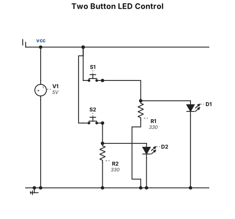
make a circuit that first button turns on first led, second button that turns on second LED
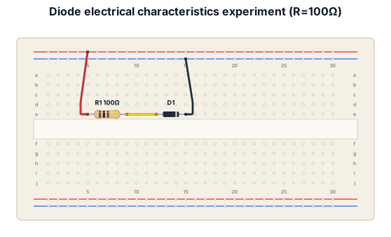
Diode의 전기적 특성 실험 저항 100옴 브레드보드 배선도를 보여줘
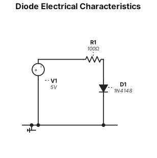
Diode의 전기적 특성 실험 저항 100옴
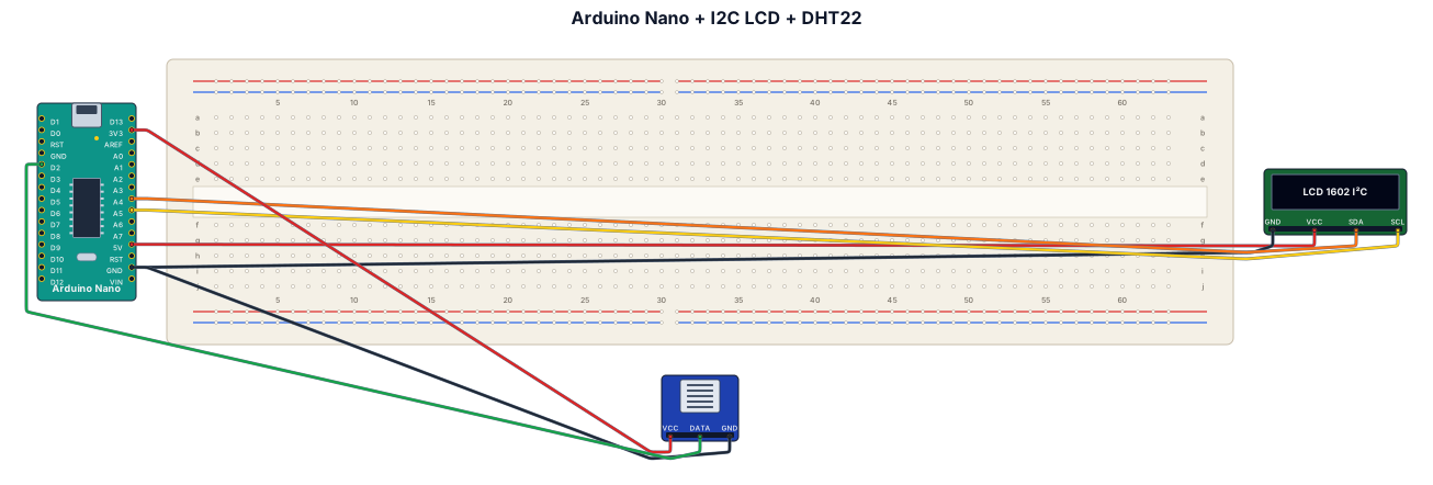
아두이노 나노에 I2C LCD 온도 센서 연결하기
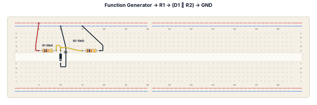
아래 조건에 맞게 브레드보드 배선도를 텍스트나 도면으로 설계해 주세요. 사용 부품:브레드보드 1개함수발생기 (Function Generator) 1개오실로스코프 (Oscilloscope) 1개저항 2개 (\(R_1 = 10\text{k}\Omega\), \(R_2 = 10\text{k}\Omega\))다이오드 1개 (\[D_{1}\]) 회로 연결 방법 (노드 기준):GND 노드 (공통 접지): 함수발생기의 음극(-) 단자, 오실로스코프의 접지(GND) 단자, 다이오드(\[D_{1}\])의 캐소드(Cathode, 띠가 있는 음극 방향), 저항 \[R_{2}\]의 한쪽 다리를 모두 브레드보드의 마이너스(-) 버스 라인(GND)에 공통 연결합니다.입력 노드 (\[V_{S}\]): 함수발생기의 양극(+) 단자와 저항 \[R_{1}\]의 한쪽 다리를 서로 연결합니다. (오실로스코프 채널 1을 이 노드에 연결)출력 노드 (\[V_{\text{OUT}}\]): 저항 \[R_{1}\]의 나머지 한쪽 다리, 다이오드(\[D_{1}\])의 애노드(Anode, 양극 방향), 저항 \[R_{2}\]의 나머지 한쪽 다리를 브레드보드의 동일한 행(Row)에 모아서 연결합니다.출력 측정: 오실로스코프 채널 2의 프로브(양극)를 3번 '출력 노드'에 연결합니다. 2. 영문(English) 프롬프트 (해외 AI 툴 사용 시 권장) [Request: Breadboard Wiring Diagram]Please generate a breadboard wiring layout based on the following connections: Components:1x Breadboard1x Function Generator1x Oscilloscope2x Resistors (\(R_1 = 10\text{k}\Omega\), \(R_2 = 10\text{k}\Omega\))1x Diode (\[D_{1}\]) Wiring Connections:GND Node: Connect Function Generator (-), Oscilloscope GND, Diode Cathode (striped side), and one lead of \[R_{2}\] to the breadboard's GND rail.Input Node (\[V_{S}\]): Connect Function Generator (+) to one lead of \[R_{1}\]. (Connect Oscilloscope CH1 here to measure \[V_{S}\])Output Node (\[V_{\text{OUT}}\]): Connect the other lead of \[R_{1}\], Diode Anode (non-striped side), and the other lead of \[R_{2}\] together in the same breadboard row.Measurement: Connect Oscilloscope CH2 to the Output Node.