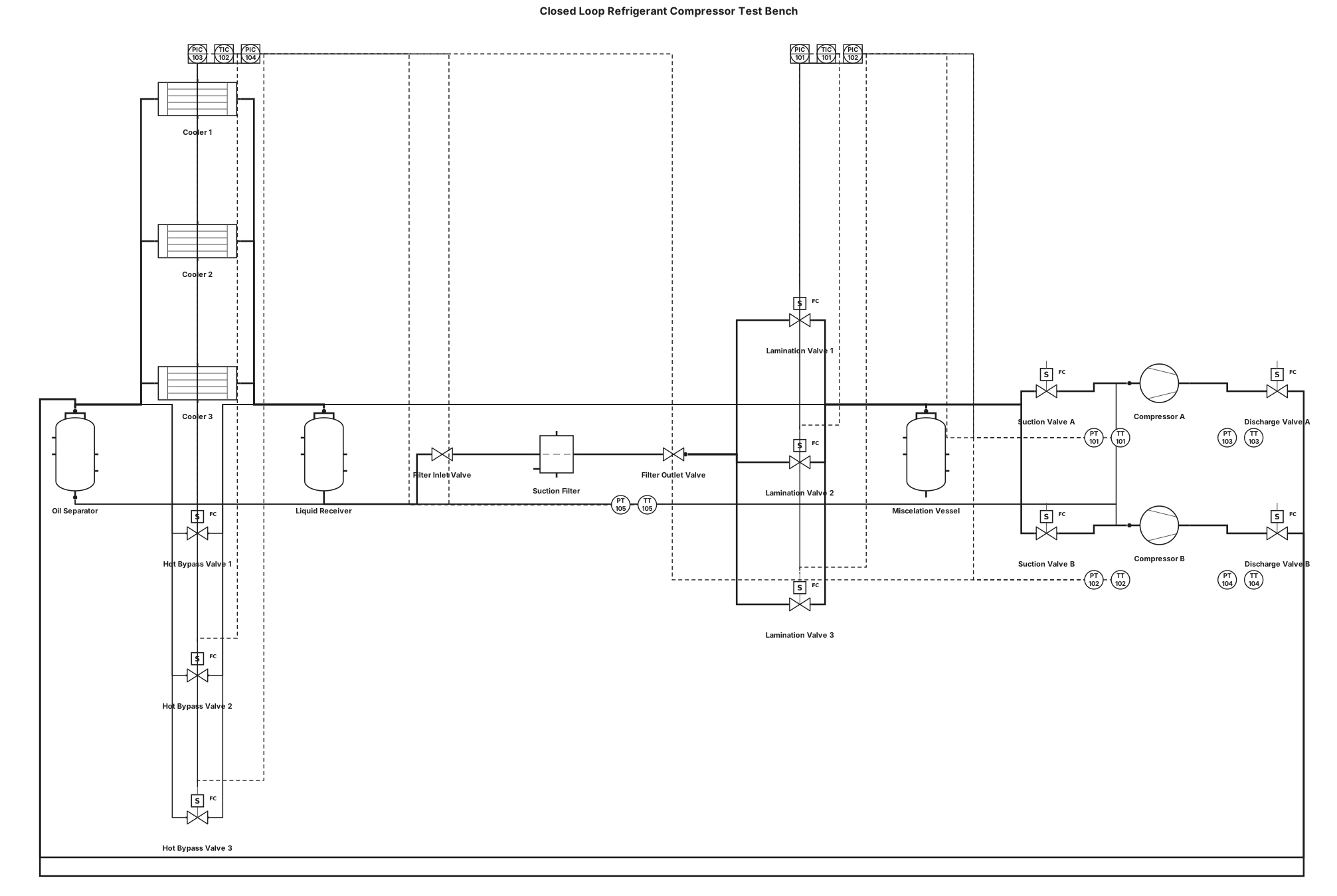
A P&ID for a closed loop refrigerant gas compressors test bench, with two compressors parallel positions. Pressure and temperature sensors at the suction and discharge of every compressor. Electrovalves at every inlet (before sensors) and outlet lines (after sensors) of the compressors. After the discharge line union, and before the coolers, an oil separator vessel. After the oil separator, three coolers in parallel. After coolers, a liquid receiver vessel. After liquid receiver, a filter with manual valves for maintenance. After exit filter valve, pressure and temperature sensors. After sensors, three lamination electrovalves in parallel. After valves, a miscelation vessel. After miscelation vessel, back to che compressors. From the oil separator bottom, lines towards the compressors for oil injection. After the oil separator, we have a bypass line with three hot bypass electrovalves that discharge into the miscelator vessel.
Diagram Examples from Real Visitor Prompts
Browse eligible diagrams shared by FreeDiagram visitors, inspect the exact prompts, and build your own version.
Browse 3281 real creationsAll visitor creations
Showing 865–888 of 3281. No stock examples or system defaults. Choose a tool, study a real result, then reopen its prompt as your starting point.
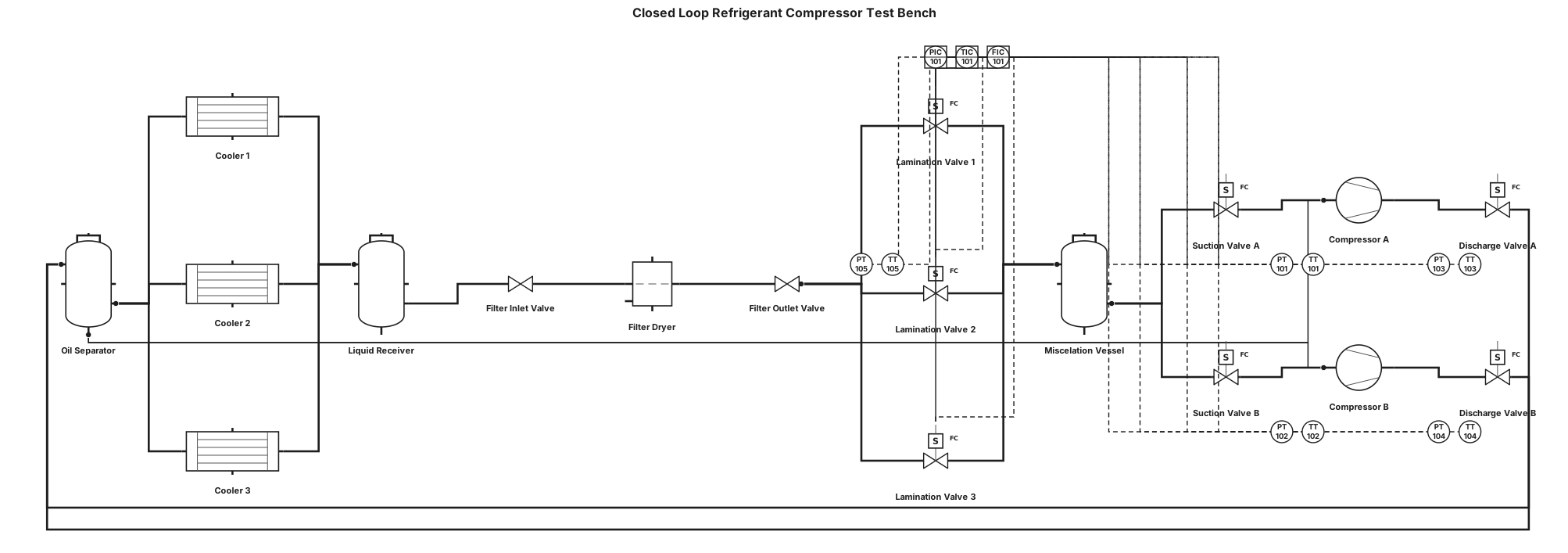
A P&ID for a closed loop refrigerant gas compressors test bench, with two compressors parallel positions. Pressure and temperature sensors at the suction and discharge of every compressor. Electrovalves at every inlet (before sensors) and outlet lines (after sensors) of the compressors. After the discharge line union, and before the coolers, an oil separator vessel. After the oil separator, three coolers in parallel. After coolers, a liquid receiver vessel. After liquid receiver, a filter with manual valves for maintenance. After exit filter valve, pressure and temperature sensors. After sensors, three lamination electrovalves in parallel. After valves, a miscelation vessel. After miscelation vessel, back to che compressors. From the oil separator bottom, lines towards the compressors for oil injection.
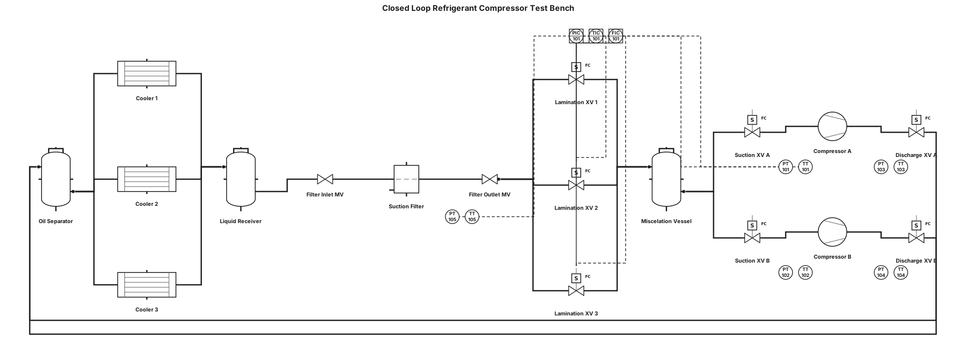
A P&ID for a closed loop refrigerant gas compressors test bench, with two compressors parallel positions. Pressure and temperature sensors at the suction and discharge of every compressor. Electrovalves at every inlet (before sensors) and outlet lines (after sensors) of the compressors. After the discharge line union, and before the coolers, an oil separator vessel. After the oil separator, three coolers in parallel. After coolers, a liquid receiver vessel. After liquid receiver, a filter with manual valves for maintenance. After exit filter valve, pressure and temperature sensors. After sensors, three lamination electrovalves in parallel. After valves, a miscelation vessel. After miscelation vessel, back to che compressors.
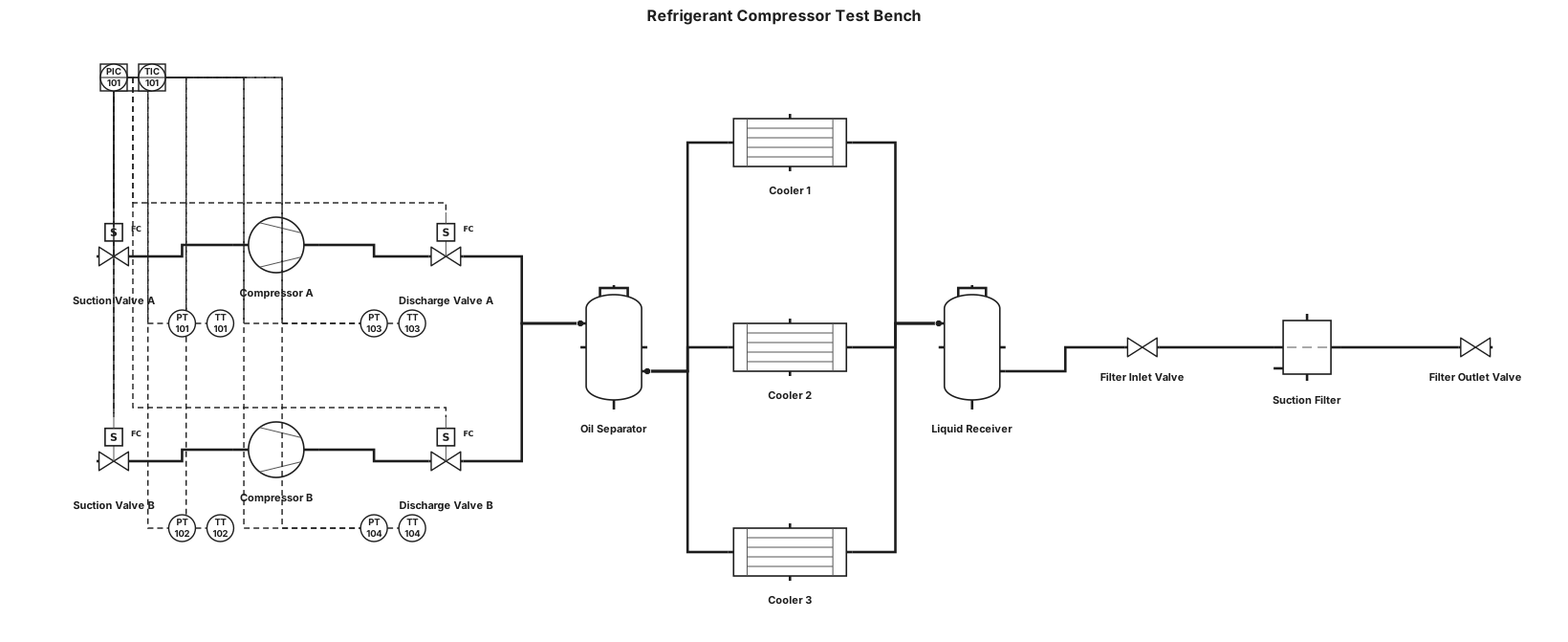
A P&ID for a closed loop refrigerant gas compressors test bench, with two compressors parallel positions. Pressure and temperature sensors at the suction and discharge of every compressor. Electrovalves at every inlet (before sensors) and outlet lines (after sensors) of the compressors. After the discharge line union, and before the coolers, an oil separator vessel. After the oil separator, three coolers in parallel. After coolers, a liquid receiver vessel. After liquid receiver, a filter with manual valves for maintenance.
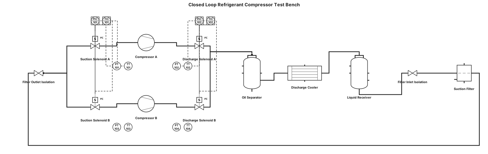
A P&ID for a closed loop refrigerant gas compressors test bench, with two compressors parallel positions. Pressure and temperature sensors at the suction and discharge of every compressor. Electrovalves at every inlet (before sensors) and outlet lines (after sensors) of the compressors. After the discharge line union, and before the coolers, an oil separator vessel. After coolers, a liquid receiver vessel. After liquid receiver, a filter with manual valves for maintenance.
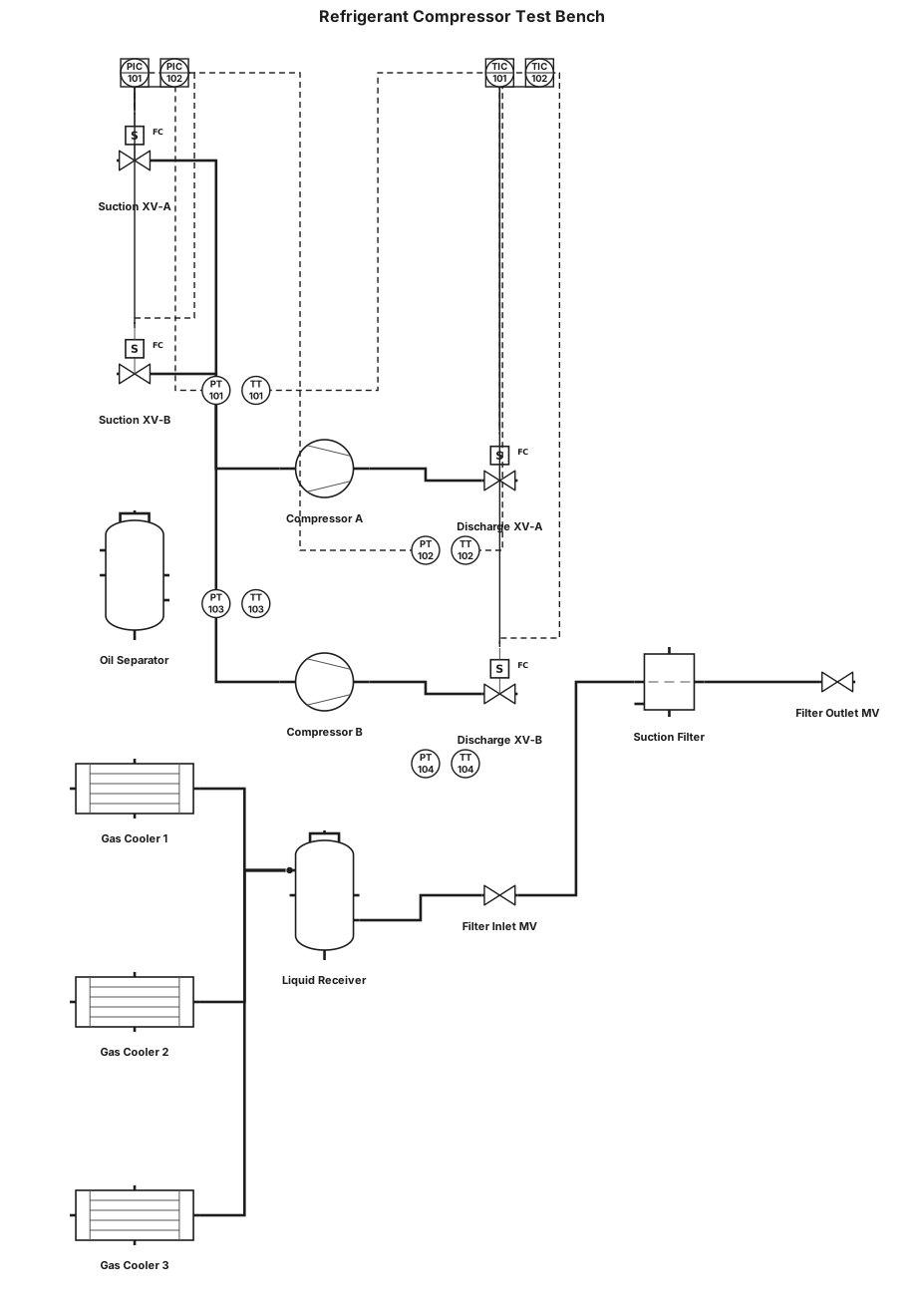
A P&ID for a closed loop refrigerant gas compressors test bench, with two compressors parallel positions, and three gas coolers in parallel. Pressure and temperature sensors at the suction and discharge of every compressor. Electrovalves at every inlet (before sensors) and outlet lines (after sensors) of the compressors. After the discharge line union, and before the coolers, an oil separator vessel. After coolers, a liquid receiver vessel. After liquid receiver, a filter with manual valves for maintenance.
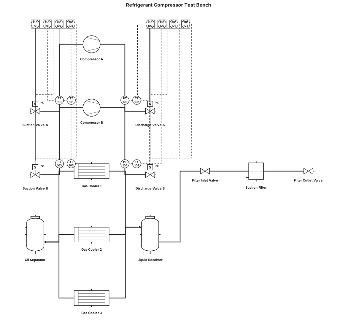
A P&ID for a closed loop refrigerant gas compressors test bench, with two compressors parallel positions. Pressure and temperature sensors at the suction and discharge of every compressor. Electrovalves at every inlet (before sensors) and outlet lines (after sensors) of the compressors. After the discharge line union, and before the coolers, an oil separator vessel. The gas cooler are three in parallel. After coolers, a liquid receiver vessel. After liquid receiver, a filter with manual valves for maintenance.
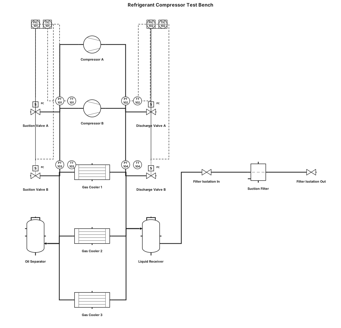
A P&ID for a closed loop refrigerant gas compressors test bench, with two compressors parallel positions. Pressure and temperature sensors at the suction and discharge of every compressor. Electrovalves at every inlet (before sensors) and outlet lines (after sensors) of the compressors. After the discharge line union, and before the cooler, an oil separator vessel. The gas cooler are three in parallel. After coolers, a liquid receiver vessel. After liquid receiver, a filter with manual valves for maintenance.
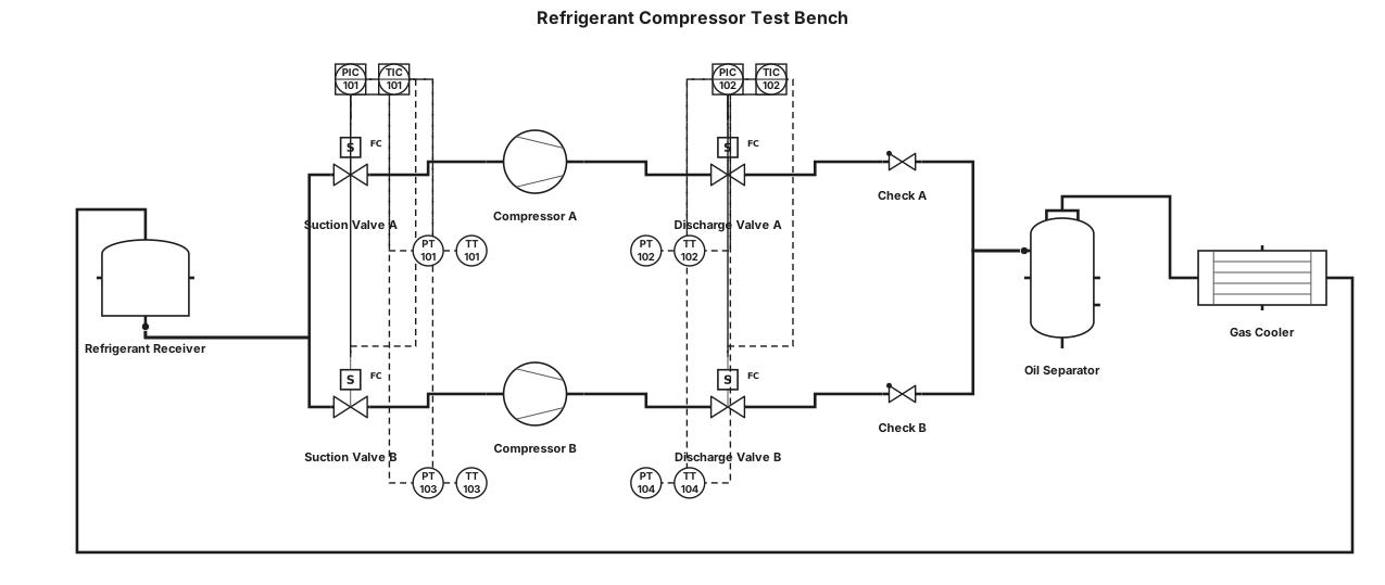
A P&ID for a closed loop refrigerant gas compressors test bench, with two compressors parallel positions. We have pressure and temperature sensors at the suction and discharge of every compressor. Electrovalves at every inlet (before sensors) and outlet lines (after sensors) of the compressors. After the discharge line union, and before the cooler, we have an oil separator vessel.
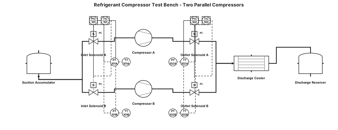
A P&ID for a closed loop refrigerant gas compressors test bench, with two compressors parallel positions. We have pressure and temperature sensors at the suction and discharge of every compressor. Electrovalves at every inlet (before sensors) and outlet lines (after sensors) of the compressors.
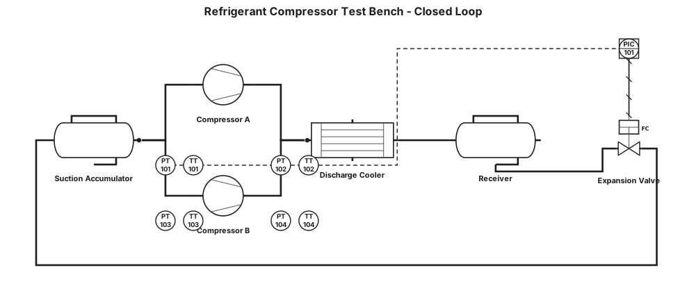
A P&ID for a closed loop refrigerant gas compressors test bench, with two compressors parallel positions. We have pressure and temperature sensors at the suction and discharge of every compressor.
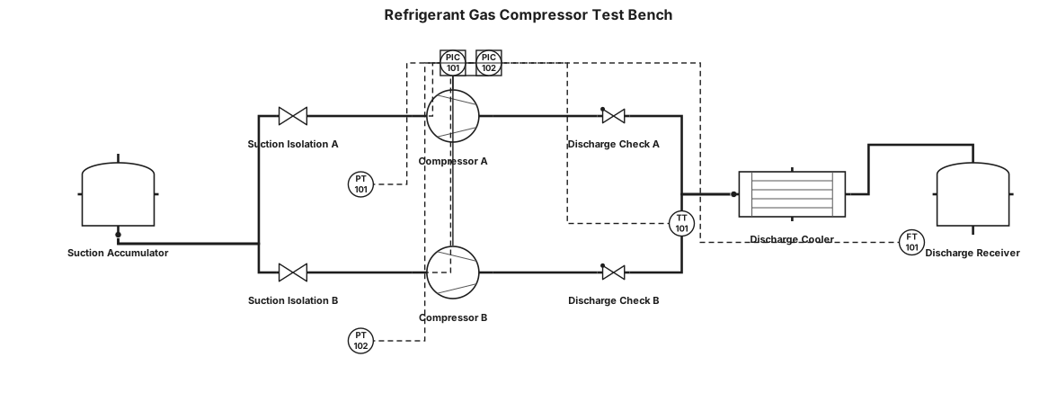
A P&ID for a refrigerant gas compressors test bench, with two compressors parallel positions.
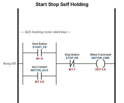
Start Stop Self Holding
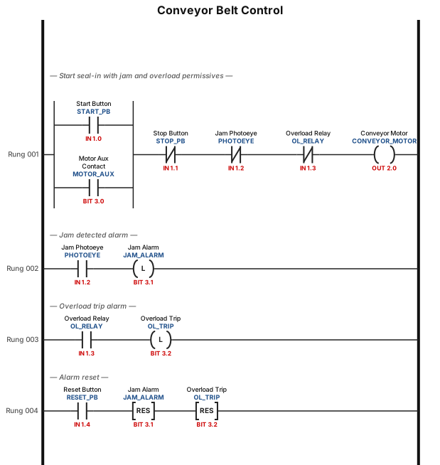
A ladder logic program for a conveyor belt system: start button seals in the motor, a photoeye stops the belt when a jam is detected, and an overload relay trips the circuit
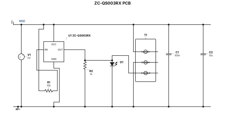
ZC-QS003RX pcb schematic
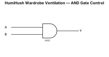
Create a clear and accurate logic gate schematic for the HumiHush wardrobe ventilation system using a two-input AND gate. Label the inputs as A (Humidity Sensor) and B (Enable Switch), and the output as Y = A · B. Show the correct AND gate symbol with both input lines connected to it and one output line labeled Y (Ventilation Fan). Include the truth table (00→0, 01→0, 10→0, 11→1). Use standard digital logic symbols, black lines, clear labels, and a plain white background suitable for a college engineering proposal.

CAN waveform at 500KBPS baud rate, address 0x12, type standard, DLC 2 and data 0xAABB
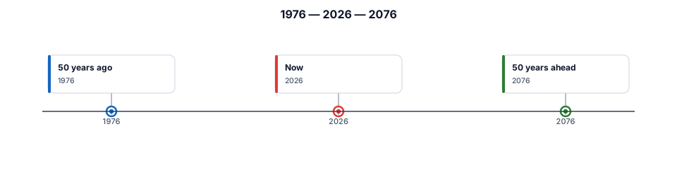
a Timeline with 2026 in the center. Add one line from 50 years ago and one line 50 years in the future to show past and future
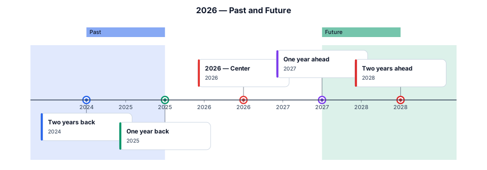
a Timeline with 2026 in the center. Add two years to either side of the center to signify past and future
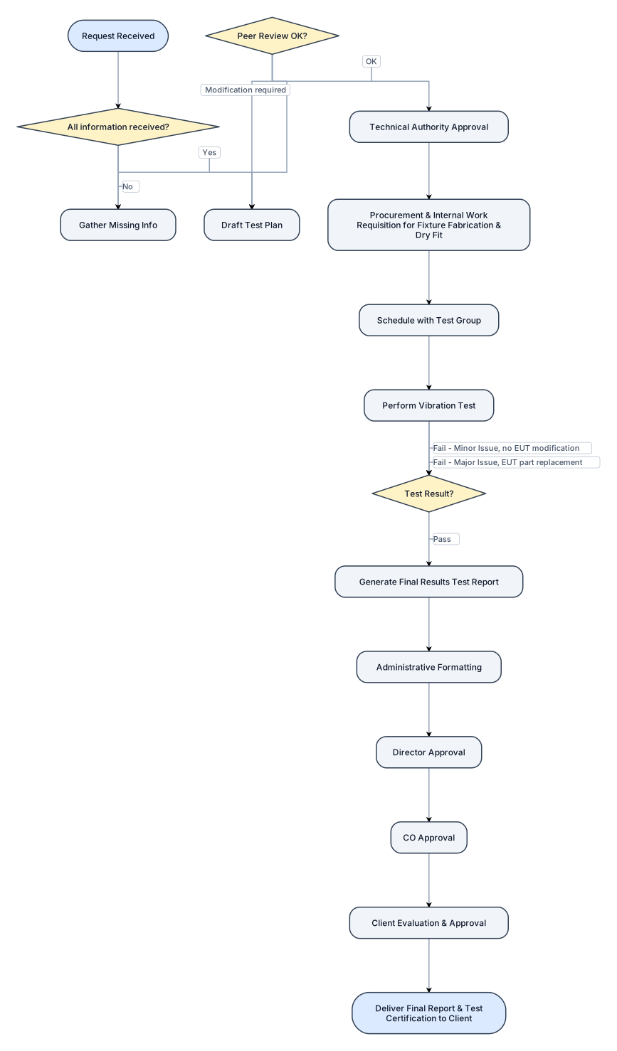
Create a flowchart for a Vibration Testing Process based on MIL-STD-167-1A: 1. Start with "Request Received", 2. if all information rx * yes go to 3 *if not all information rx go to "Gather Missing Info" then comme back to step 2. 3. Move to "Draft Test Plan" (incorporating Purpose, MIL-STD-167-1A, Requirements, Setup, Conduct, and Acceptance Criteria). 4. Pass through "Peer Review" *if ok then continue next step *if modificaion required come back to step 3. 5.and "Technical Authority Approval". 5. Proceed to "Procurement & Internal Work Requisition for Fixture Fabrication & Dry Fit". 6. Move to "Schedule with Test Group" 7. "Perform Vibration Test". 7. Add a Decision Node after testing: * If PASS: Go to step 8 "Generate Final Results Test Report". * If FAIL (Minor Issue - no EUT modification): Restart from the last test portion. * If FAIL (Major Issue - EUT part replacement): Restart testing completely.from step 7 8. From "Generate Final Results Test Report", loop through the Approval Pipeline: * Administrative Formatting -> Director Approval -> CO Approval -> Client Evaluation & Approval. 8. End with "Deliver Final Report & Test Certification to Client".
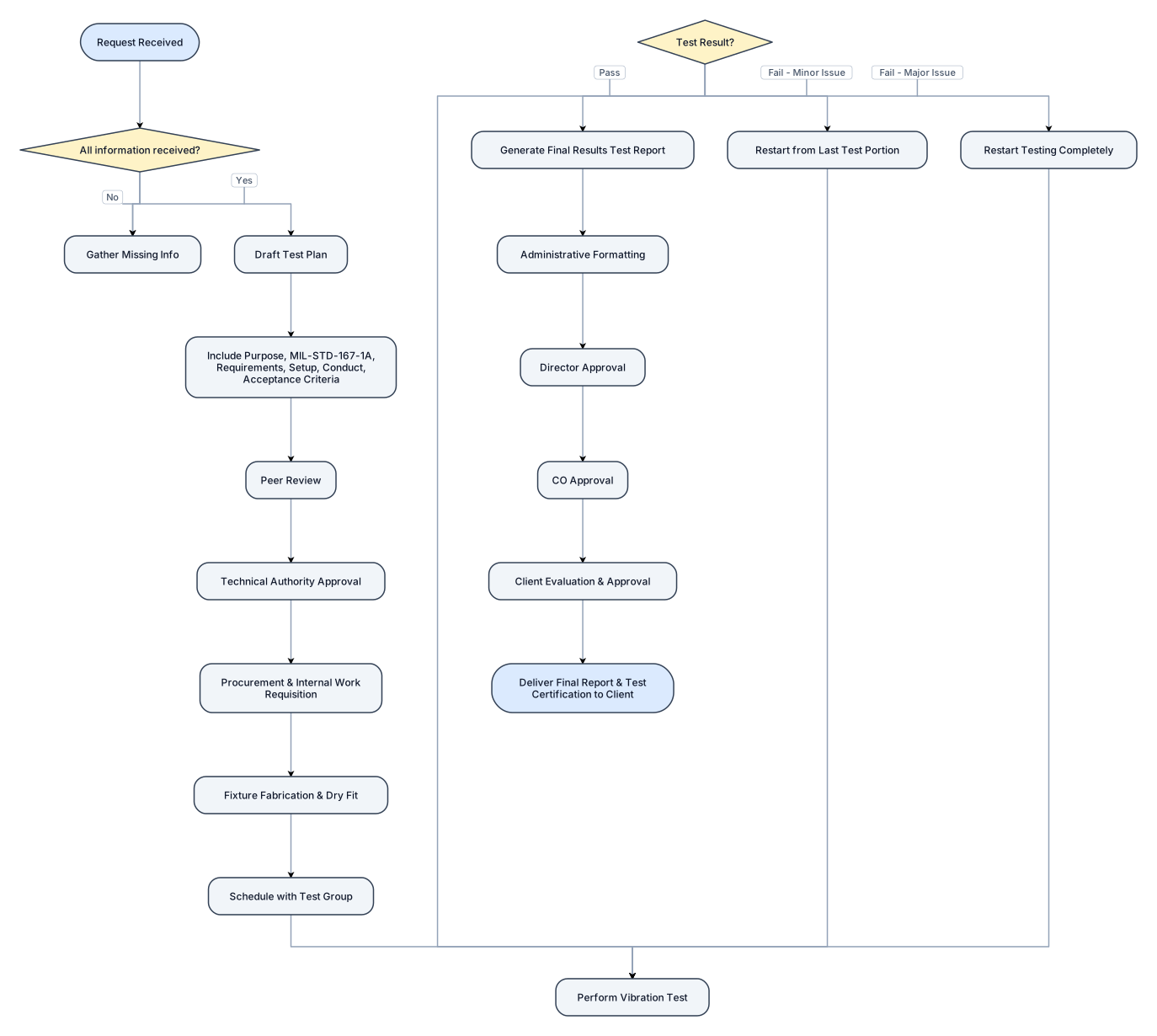
Create a flowchart for a Vibration Testing Process based on MIL-STD-167-1A: 1. Start with "Request Received", 2. if all information rx * yes go to 3 *if not all information rx go to "Gather Missing Info" then comme back to step 2. 3. Move to "Draft Test Plan" (incorporating Purpose, MIL-STD-167-1A, Requirements, Setup, Conduct, and Acceptance Criteria). 4. Pass through "Peer Review" and "Technical Authority Approval". 5. Proceed to "Procurement & Internal Work Requisition for Fixture Fabrication & Dry Fit". 6. Move to "Schedule with Test Group" and "Perform Vibration Test". 7. Add a Decision Node after testing: * If PASS: Go to "Generate Final Results Test Report". * If FAIL (Minor Issue - no EUT modification): Restart from the last test portion. * If FAIL (Major Issue - EUT part replacement): Restart testing completely. 7. From "Generate Final Results Test Report", loop through the Approval Pipeline: * Administrative Formatting -> Director Approval -> CO Approval -> Client Evaluation & Approval. 8. End with "Deliver Final Report & Test Certification to Client".
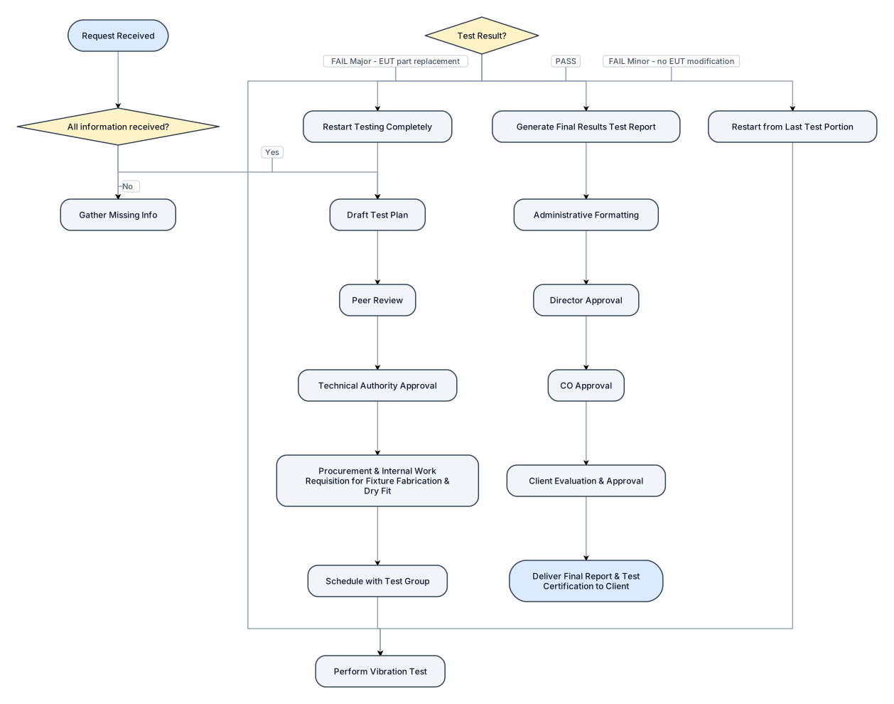
Create a flowchart for a Vibration Testing Process based on MIL-STD-167-1A: 1. Start with "Request Received", 2. if all information rx go to 3 if not all information rx "Gather Missing Info" then if all rx continue to step 3. 3. Move to "Draft Test Plan" (incorporating Purpose, MIL-STD-167-1A, Requirements, Setup, Conduct, and Acceptance Criteria). 4. Pass through "Peer Review" and "Technical Authority Approval". 5. Proceed to "Procurement & Internal Work Requisition for Fixture Fabrication & Dry Fit". 6. Move to "Schedule with Test Group" and "Perform Vibration Test". 7. Add a Decision Node after testing: * If PASS: Go to "Generate Final Results Test Report". * If FAIL (Minor Issue - no EUT modification): Restart from the last test portion. * If FAIL (Major Issue - EUT part replacement): Restart testing completely. 7. From "Generate Final Results Test Report", loop through the Approval Pipeline: * Administrative Formatting -> Director Approval -> CO Approval -> Client Evaluation & Approval. 8. End with "Deliver Final Report & Test Certification to Client".
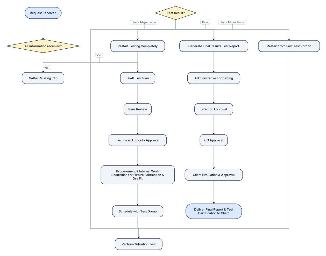
Create a flowchart for a Vibration Testing Process based on MIL-STD-167-1A: 1. Start with "Request Received", 2. if all information rx go to 3 if not all information rx "Gather Missing Info". 3. Move to "Draft Test Plan" (incorporating Purpose, MIL-STD-167-1A, Requirements, Setup, Conduct, and Acceptance Criteria). 4. Pass through "Peer Review" and "Technical Authority Approval". 5. Proceed to "Procurement & Internal Work Requisition for Fixture Fabrication & Dry Fit". 6. Move to "Schedule with Test Group" and "Perform Vibration Test". 7. Add a Decision Node after testing: * If PASS: Go to "Generate Final Results Test Report". * If FAIL (Minor Issue - no EUT modification): Restart from the last test portion. * If FAIL (Major Issue - EUT part replacement): Restart testing completely. 7. From "Generate Final Results Test Report", loop through the Approval Pipeline: * Administrative Formatting -> Director Approval -> CO Approval -> Client Evaluation & Approval. 8. End with "Deliver Final Report & Test Certification to Client".
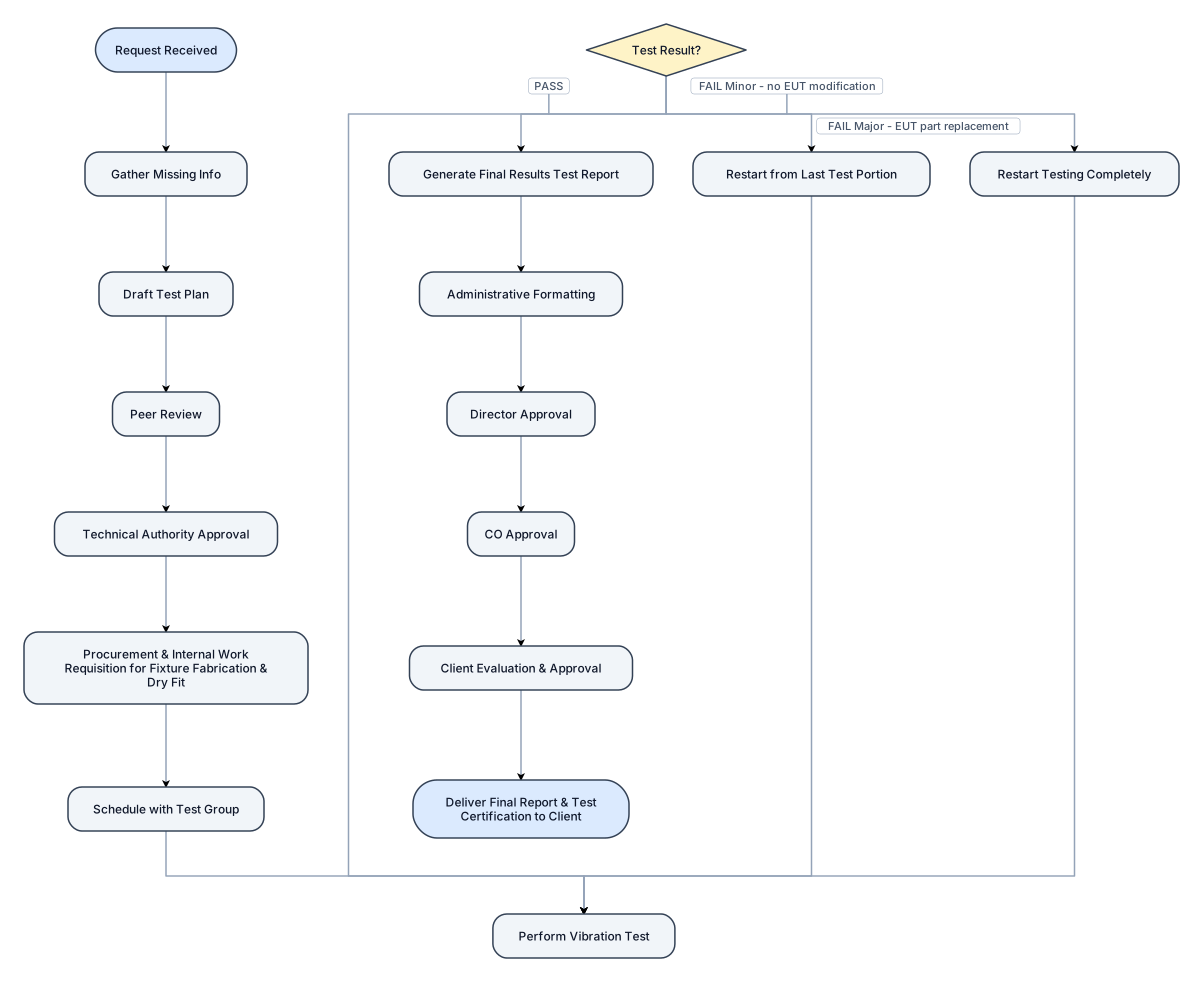
Create a flowchart for a Vibration Testing Process based on MIL-STD-167-1A: 1. Start with "Request Received", then "Gather Missing Info". 2. Move to "Draft Test Plan" (incorporating Purpose, MIL-STD-167-1A, Requirements, Setup, Conduct, and Acceptance Criteria). > 3. Pass through "Peer Review" and "Technical Authority Approval". > 4. Proceed to "Procurement & Internal Work Requisition for Fixture Fabrication & Dry Fit". > 5. Move to "Schedule with Test Group" and "Perform Vibration Test". 6. Add a Decision Node after testing: * If PASS: Go to "Generate Final Results Test Report". * If FAIL (Minor Issue - no EUT modification): Restart from the last test portion. * If FAIL (Major Issue - EUT part replacement): Restart testing completely. 7. From "Generate Final Results Test Report", loop through the Approval Pipeline: * Administrative Formatting -> Director Approval -> CO Approval -> Client Evaluation & Approval. 8. End with "Deliver Final Report & Test Certification to Client".