![Ladder Logic example: ]packake on conveyor sensor at beginning op push staty starts if senos detects over load must be used must use pb3 estop](https://psvtykrtciekraoilfux.supabase.co/storage/v1/object/public/gallery-assets/freediagram/feed/1428933c-654b-45fa-b532-5568260da686.svg)
]packake on conveyor sensor at beginning op push staty starts if senos detects over load must be used must use pb3 estop
NODE ARCHIVE · REAL DIAGRAM BRIEFS
Diagram Examples from Real Visitor Prompts
Browse eligible diagrams shared by FreeDiagram visitors, inspect the exact prompts, and build your own version.
Browse 1008 real creationsCOMMUNITY OUTPUTS · EXACT PROMPTS
Ladder Logic
Showing 1–13 of 13. No stock examples or system defaults. Choose a tool, study a real result, then reopen its prompt as your starting point.
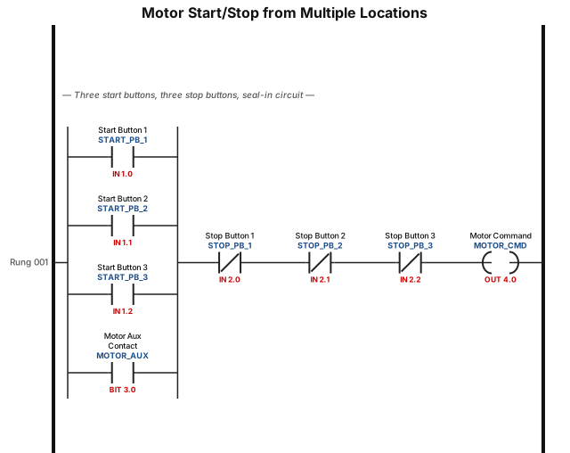
Create a single rung program that can start a motor from three different start locations (any one of which can start the motor individually), and three stop buttons (Any one of which can stop the motor). The Motor will continue to run after the start button is released
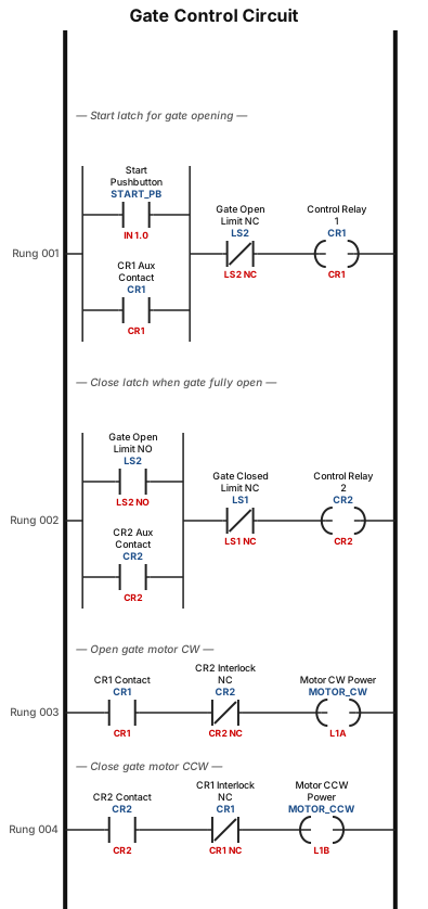
A reversible motor is used to open and close a gate. The motor has three terminals: L1A, L1B, and L2. When L2 is connected to the ground and power is applied to L1A, the motor runs clockwise, CW, direction, opening the gate. When power is applied to L1B, the motor runs counterclockwise, CCW, direction, closing the gate. The gate has two limit switches: LS1 is activated when the gate is closed, and LS2 is activated when the gate is open. Each limit switch has one normally open. NO, contact and one normally closed, NC, contact. Two control relays, CR1 and CR2, are used in the gate control circuit. These relays have two NO contacts and two NC contacts. A NO pushbutton START switch is used to initiate the opening of the gate. Draw a ladder diagram that will open the gate after a momentary closure of the START switch, close the gate immediately after the gate is fully open, and turn OFF the power to the motor when the gate is closed. Your circuit must include an interlock feature that will not allow simultaneous application of power on L1A and L1B.
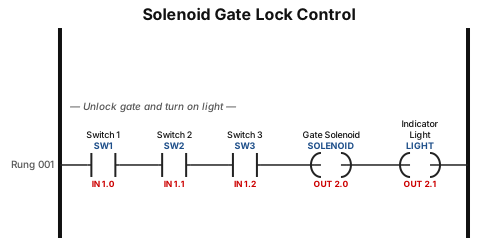
A solenoid-operated lock is used on the gate of an enclosed storage area. When the solenoid is activated, the gate is unlocked, and a light goes ON. Three pushbutton switches are used in the solenoid control circuit, SW1, SW2, and SW3. The three switches are located such that a single operator can close only one switch at a time, two operators are required to close two switches, and three operators are required to close all three switches.
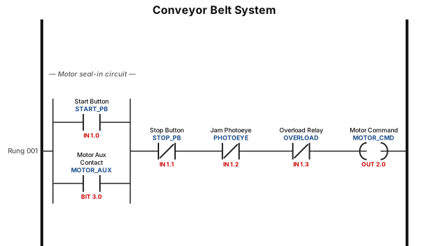
A ladder logic program for a conveyor belt system: start button seals in the motor, a photoeye stops the belt when a jam is detected, and an overload relay trips the circuit
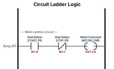
P3: Draw the ladder logic diagram for given circuit, use a suitable software tool/platform.
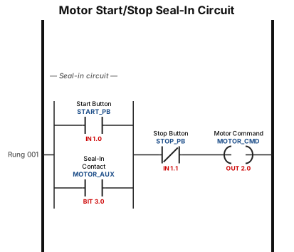
A motor start/stop seal-in circuit with a normally open start button, a normally closed stop button, and a seal-in contact around the start button
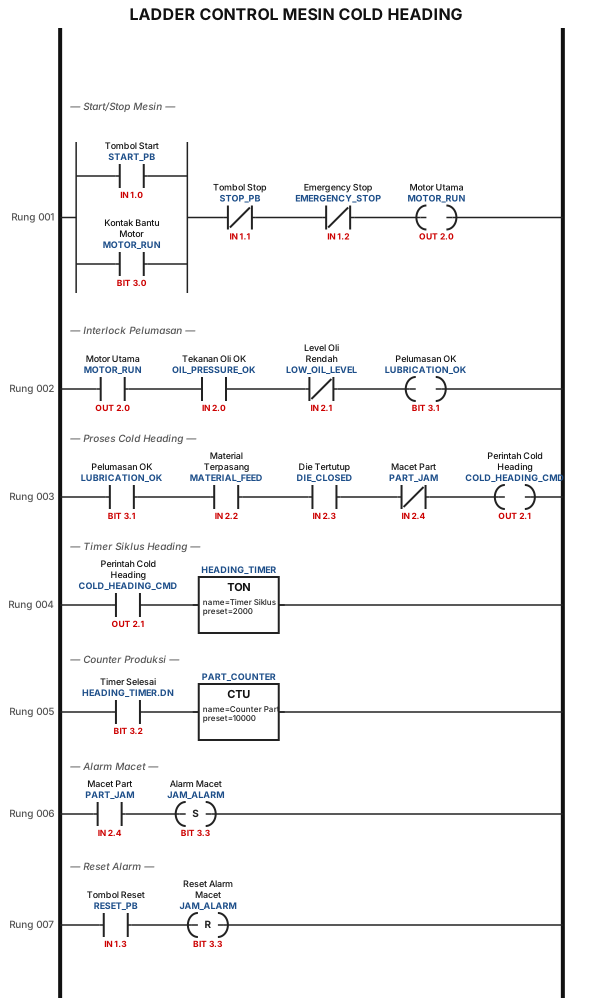
LADDER CONTROL MESIN COLD HEADING
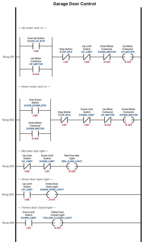
A motorized overhead garage door is to be operated automatically to preset open and closed positions. The field devices include one of each of the following: • Reversing motor contactor for the up and down directions. • Normally open down limit switch to sense when the door is fully closed. • Normally open-held closed up-limit switch to sense when the door is fully opened. • Normally open door up button for the up direction. • Normally open door down button for the down direction. • Normally closed door stop button for stopping the door. • Red door ajar light to signal when the door is partially open. • Green door open light to signal when the door is fully open. • Yellow door closed light to signal when the door is fully closed. The sequence of operation requires that: • When the up button is pushed, the up-motor contactor energizes and the door travels upward until the up-limit switch is actuated. • When the down button is pushed, the down motor contactor energizes and the door travels down until the down limit switch is actuated. • When the stop button is pushed, the motor stops. The motor must be stopped before it can change direction Tag Device Type Function I:3/0 Up limit NO-held closed Detects when door is fully open I:3/1 Down limit NO Detects when door is fully closed I:3/4 Door up button NO Command to raise door I:3/5 Door down button NO Command to lower door I:3/7 Stop door button NC Stops motor immediately Tag Device Function O:4/0 Red light Door ajar (neither limit made) O:4/1 Green light Door fully open O:4/2 Yellow light Door fully closed O:4/3 Up motor contactor Energizes motor upward O:4/4 Down motor contactor Energizes motor downward
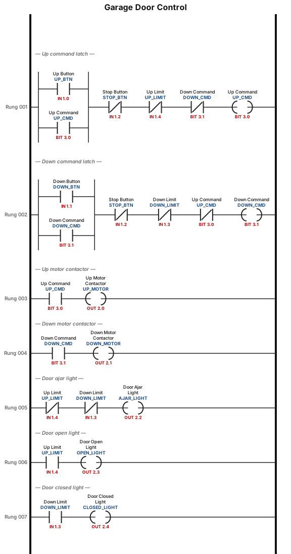
A motorized overhead garage door is to be operated automatically to preset open and closed positions. The field devices include one of each of the following: • Reversing motor contactor for the up and down directions. • Normally open down limit switch to sense when the door is fully closed. • Normally open-held closed up-limit switch to sense when the door is fully opened. • Normally open door up button for the up direction. • Normally open door down button for the down direction. • Normally closed door stop button for stopping the door. • Red door ajar light to signal when the door is partially open. • Green door open light to signal when the door is fully open. • Yellow door closed light to signal when the door is fully closed. The sequence of operation requires that: • When the up button is pushed, the up-motor contactor energizes and the door travels upward until the up-limit switch is actuated. • When the down button is pushed, the down motor contactor energizes and the door travels down until the down limit switch is actuated. • When the stop button is pushed, the motor stops. The motor must be stopped before it can change direction.
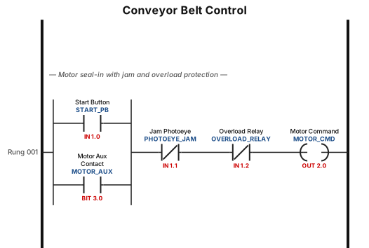
A ladder logic program for a conveyor belt system: start button seals in the motor, a photoeye stops the belt when a jam is detected, and an overload relay trips the circuit
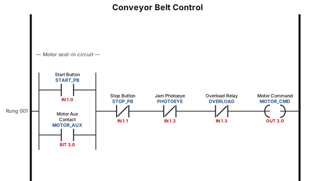
A ladder logic program for a conveyor belt system: start button seals in the motor, a photoeye stops the belt when a jam is detected, and an overload relay trips the circuit
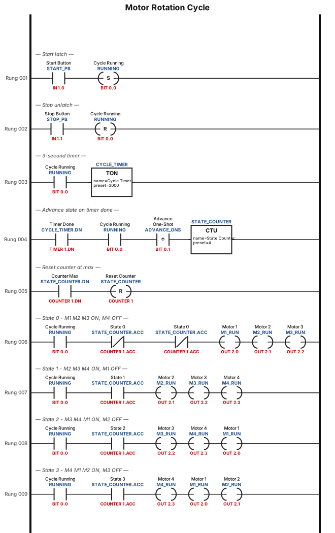
By pressing the start button: motors M1, M2, and M3 all run together. After 3 seconds: M1 stops and M4 starts. After 3 seconds: M2 stops and M1 starts. After 3 seconds: M3 stops and M2 starts. After 3 seconds: M4 stops and M3 starts. This cycle repeats continuously (a rotation among the 4 motors, with 3 always running at the same time, and every 3 seconds one motor changes). There are three important execution conditions: Without using a comparator instruction. The start button has no effect after the process begins (it is not a stop button). State must be preserved when stopping (resume from the last state when restarted). Implementation is required using a Ladder Diagram.
Focused examples and prompt ideas
Start with the complete visitor wall above, then use these focused collections when you want a narrower subject and more prompt context.
The first curated collection is being prepared.