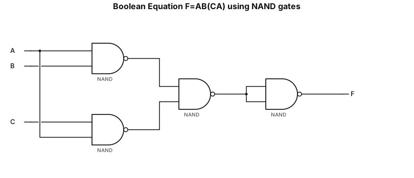
draw the logic diagram showing the implementation of the boolean equation using NAND gate F=AB(CA)
NODE ARCHIVE · REAL DIAGRAM BRIEFS
Diagram Examples from Real Visitor Prompts
Browse eligible diagrams shared by FreeDiagram visitors, inspect the exact prompts, and build your own version.
Browse 3261 real creationsCOMMUNITY OUTPUTS · EXACT PROMPTS
Boolean Expression To Logic Circuit
Showing 1–24 of 98. No stock examples or system defaults. Choose a tool, study a real result, then reopen its prompt as your starting point.
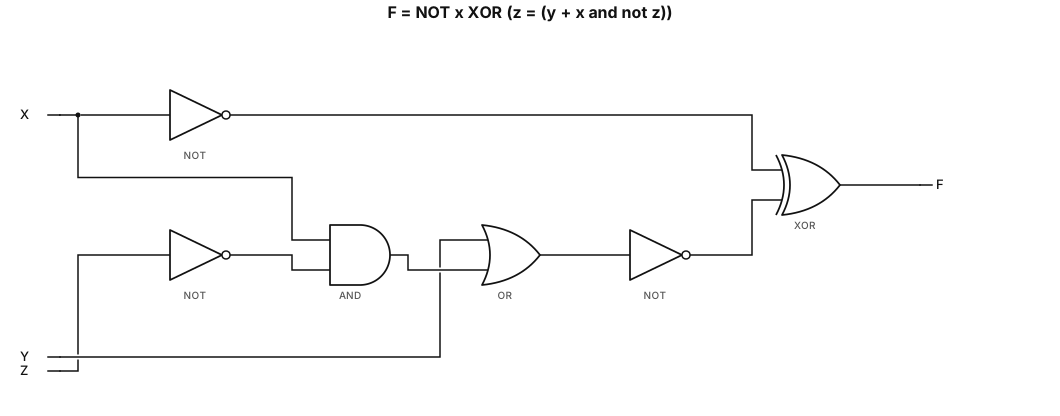
Draw the logic circuit diagram for F = NOT x XOR (z = (y + x and not z)), strictly using NOT gates and two-input AND/OR gates. Inputs X, Y, Z; output F.
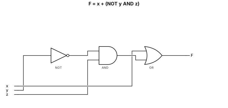
Draw the logic circuit diagram for F = x + (NOT y AND z)
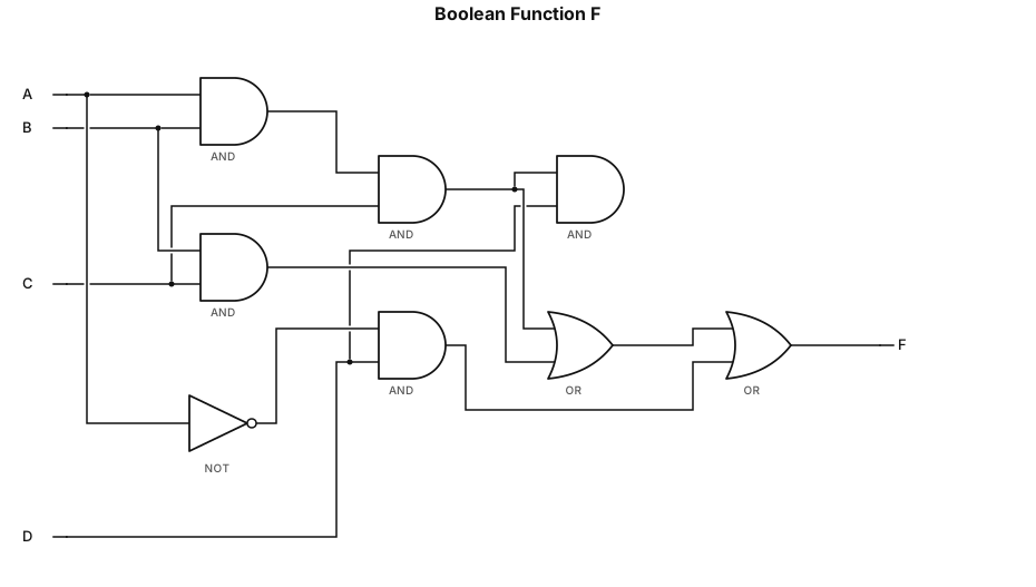
F=ABCD+BC+A'D
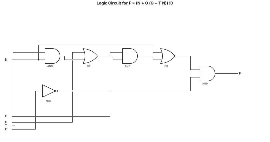
Draw the logic circuit diagram for F = (N + O (G + T N)) !D
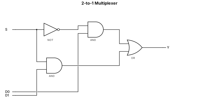
Draw one complete logic circuit diagram for a 2-to-1 multiplexer using only NOT gates, two-input AND gates, and a two-input OR gate. The circuit must have three inputs: S (select), D0 (data input 0), and D1 (data input 1). It must have one output, Y. Implement the Boolean expression: Y = (NOT S AND D0) OR (S AND D1) Connect S to a NOT gate to generate NOT S. Connect NOT S and D0 to the first two-input AND gate. Connect S and D1 to the second two-input AND gate. Connect the outputs of both AND gates to a two-input OR gate. The output of the OR gate must be labeled Y. Label all inputs, gates, wires, and the output clearly. Show all connections accurately in a single diagram. Do not add unnecessary gates.
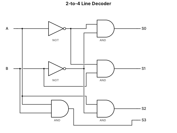
Draw one complete logic circuit diagram for a 2-to-4 line decoder, strictly using NOT gates and two-input AND gates. The circuit must have two inputs, A and B, and four outputs, S0, S1, S2, and S3. Use shared input lines A and B. Add NOT gates to generate NOT A and NOT B. Connect the signals to four separate two-input AND gates as follows: S0 = NOT A AND NOT B S1 = NOT A AND B S2 = A AND NOT B S3 = A AND B Each AND gate must produce exactly one output. Label all input lines, NOT gates, AND gates, and output lines clearly. Show all wires and connections accurately. The final result must be a single complete decoder circuit, not four separate diagrams. Do not omit any connections or add unnecessary gates.
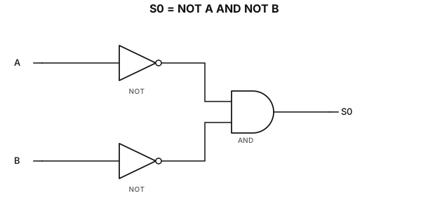
Draw the logic circuit diagram for S0 = NOT A AND NOT B, strictly using NOT gates and two-input AND gates. Inputs A, B; output S0.
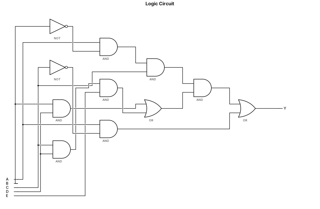
Draw the logic circuit diagram for A*B'*C*(B*D + C*D*E) + A*C'
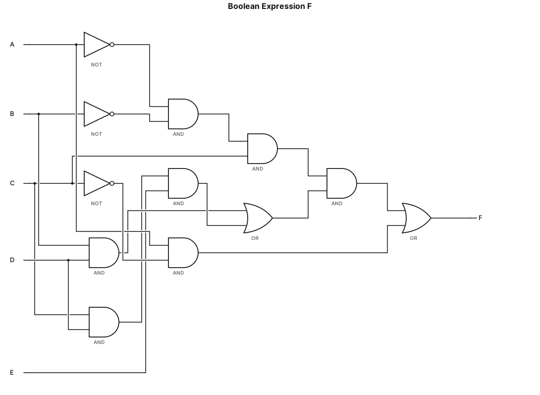
F = A'*B'*C*(B*D + C*D*E) + A*C'
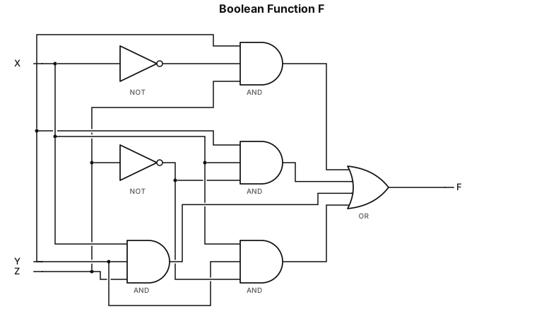
F = YX'Z + YXZ' + XYZ + XYZ'
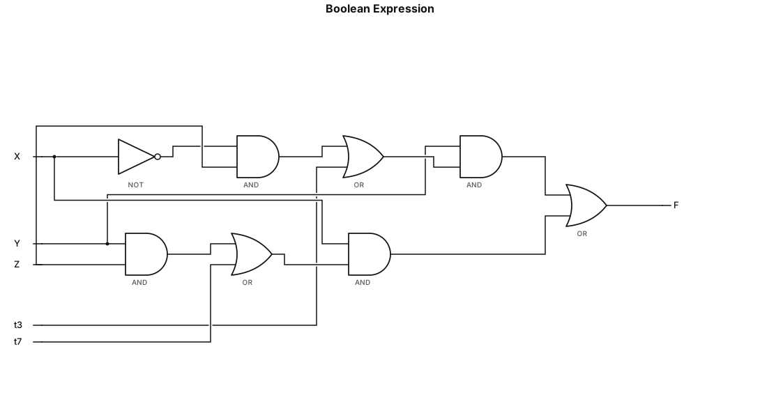
F = Y(X'Z + XZ') + X(YZ + YZ')
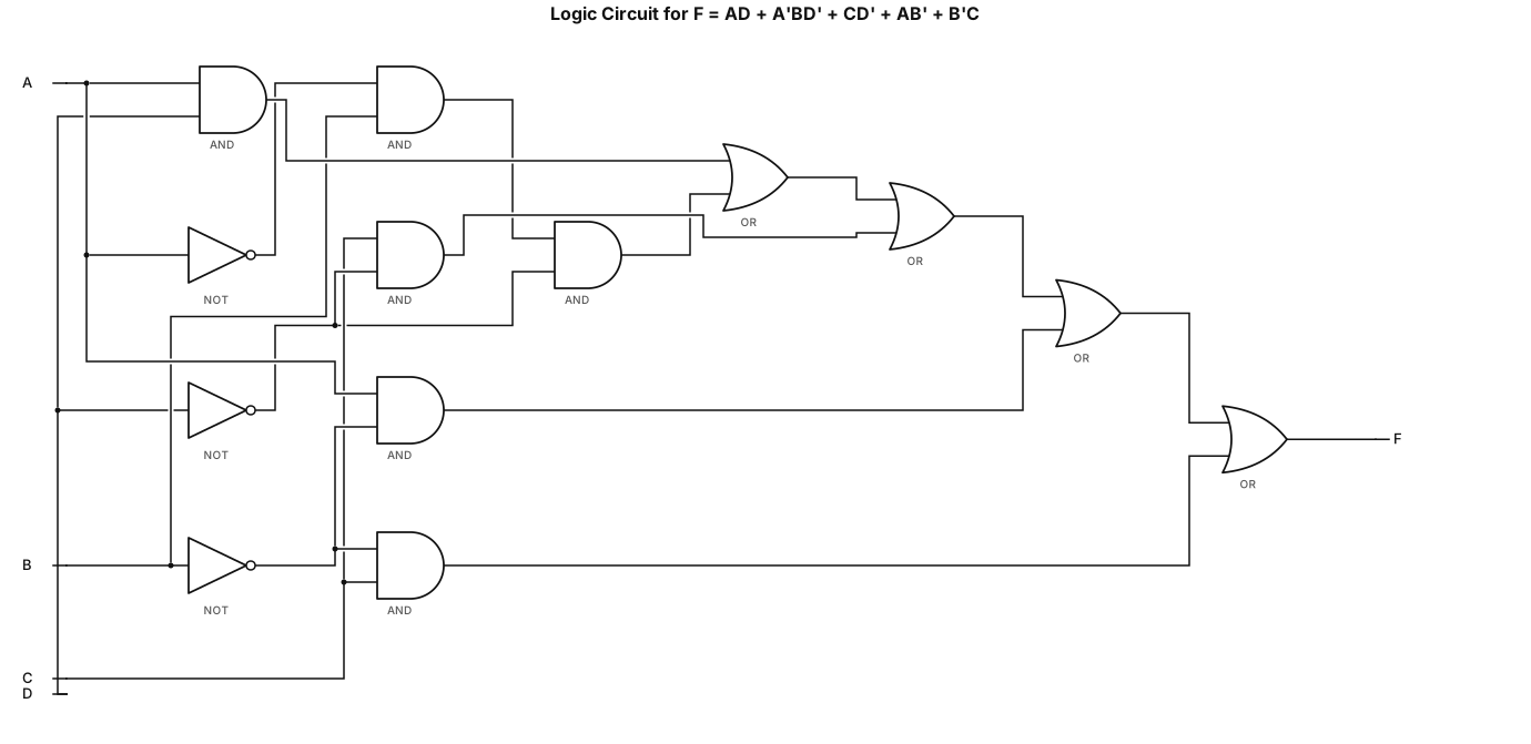
Draw the logic circuit diagram for F = AD+A'BD'+CD'+AB'+B'C
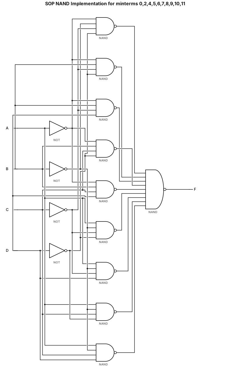
i have a question of sum of product which gives output on these values 0,2,4,5,6,7,8,9,10,11 so make a circuit using nand implemenation kindly use k-map to simplify it then make implimentation circuit
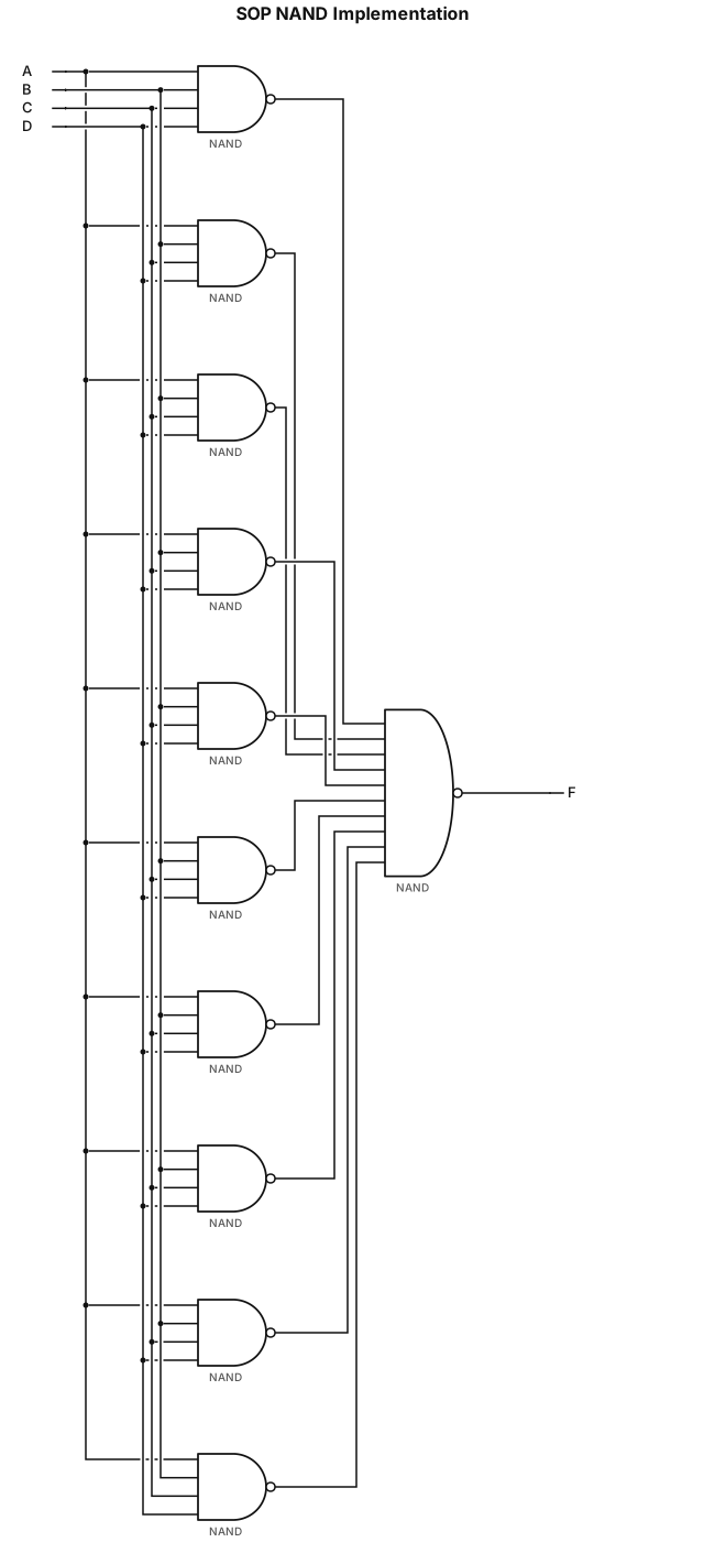
i have a question of sum of product which gives output on these values 0,2,4,5,6,7,8,9,10,11 so make a circuit using nand implemenation
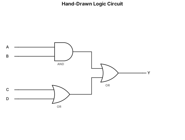
Create a simple hand-drawn digital logic gate diagram on a plain white background, similar to a student-drawn logic circuit. - Inputs A and B are connected to an AND gate on the upper left. - Inputs C and D are connected to an OR gate on the lower left. - The output of the AND gate is labeled **and(a_b)**. - The output of the lower OR gate is labeled **or(c_d)**. - Both outputs connect to a final OR gate on the right side. - **Position the final OR gate in the upper-right area, higher than the center of the diagram. Do not place it in the middle.** - Connect both gate outputs neatly to the final OR gate, then connect its output to Y. - Keep the labels A, B, C, D, and Y inside simple circles. - Use black hand-drawn lines, clear logic gate symbols, and handwritten-style labels. - Make the diagram clean, simple, and easy to understand, with no extra decorations. - Maintain the same general layout as the reference image, except move the final OR gate upward.
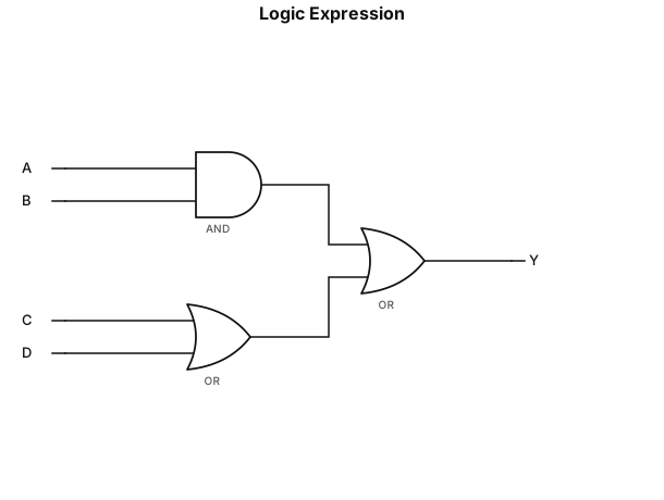
(A AND B) OR (C OR D) DRAW
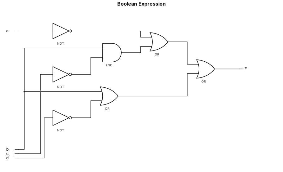
F = (a' + (b * c')) + (b + d')
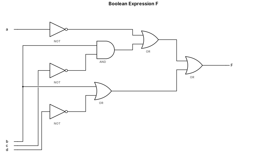
The given Boolean expression is: \[ F=(a'\lor(b\land c'))\lor(b\lor d') \] The circuit in the provided answer is roughly correct in concept, but the final gate connections are unclear.
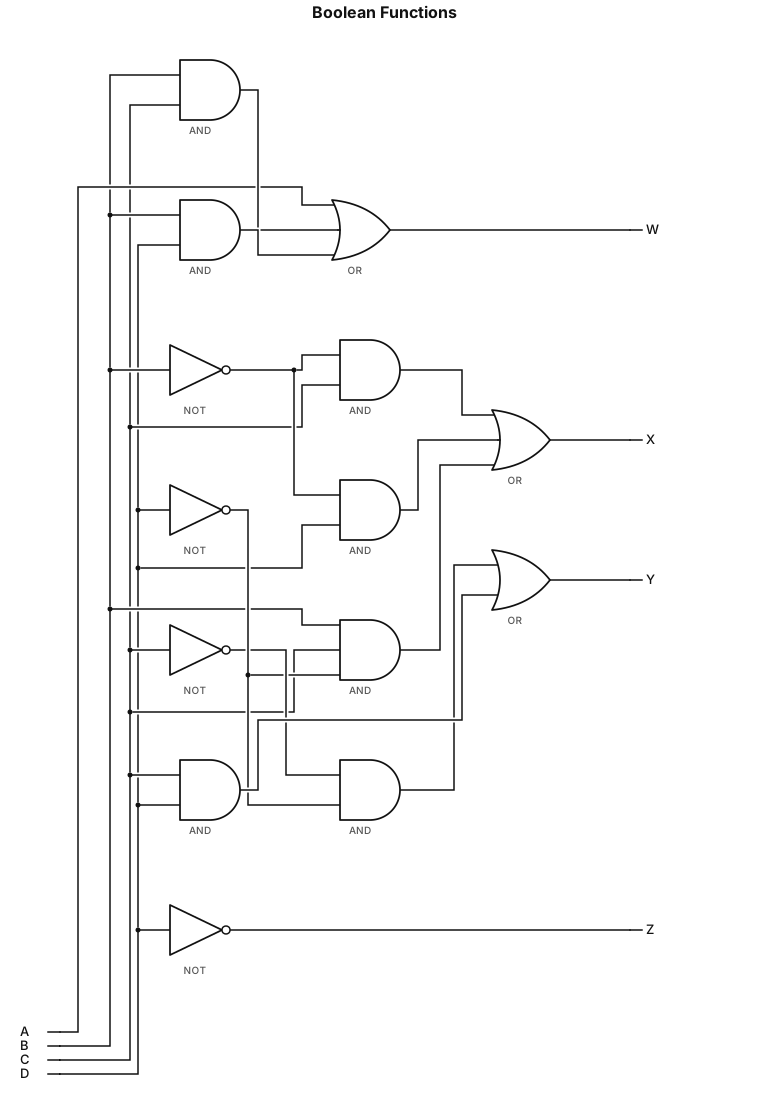
W=A+BC+BD;X=¯B C+¯B D+B¯C ¯D;Y=C'D'+CD; Z=¯D with 2 input gates
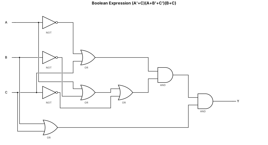
(A'+C)(A+B'+C')(B+C) with 2 input gates
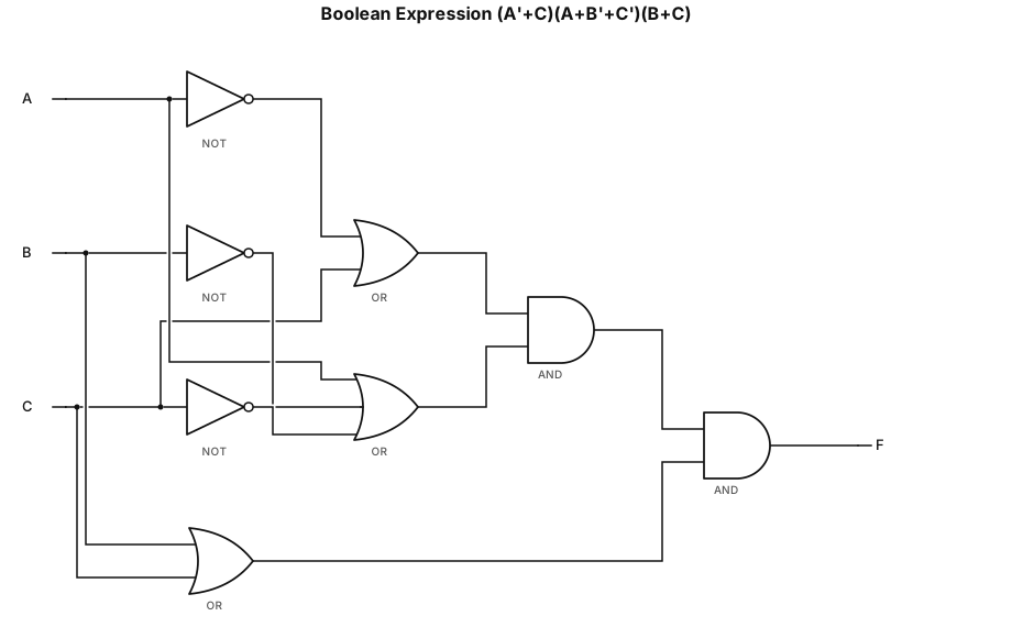
(A'+C)(A+B'+C')(B+C)
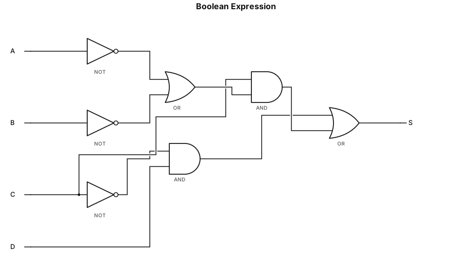
\mathrm{S}=\bar{\mathrm{C}}\mathrm{D}+\mathrm{C}\bar{\mathrm{D}}\ (\bar{\mathrm{A}}+\bar{\mathrm{B}})
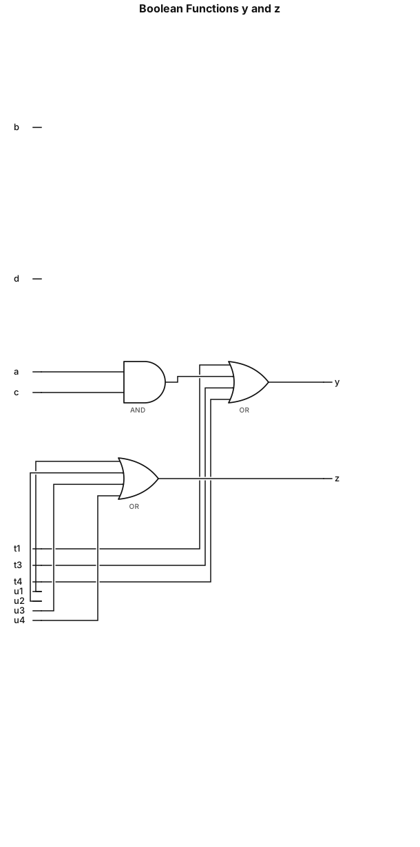
y = a'c' + ac + ab'd + bcd'; z = a'b'd + ab'd + bc'd' + bcd';