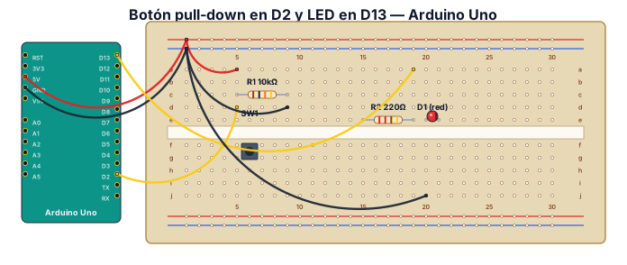
Diagrama de cableado de una placa de prototipos para un Arduino Uno que lee la pulsación de un botón y enciende un LED: botón con resistencia pull-down en D2, LED con resistencia de 220 ohmios en D13.
NODE ARCHIVE · REAL DIAGRAM BRIEFS
Diagram Examples from Real Visitor Prompts
Browse eligible diagrams shared by FreeDiagram visitors, inspect the exact prompts, and build your own version.
Browse 1008 real creationsCOMMUNITY OUTPUTS · EXACT PROMPTS
Breadboard Wiring
Showing 1–15 of 15. No stock examples or system defaults. Choose a tool, study a real result, then reopen its prompt as your starting point.
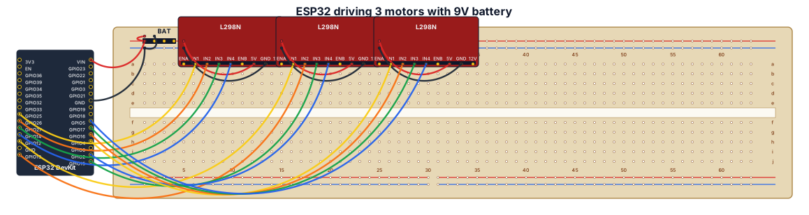
A breadboard wiring diagram for an ESP32 that drives a motor to spin 3 different wheels. All powered by a 9-volt battery
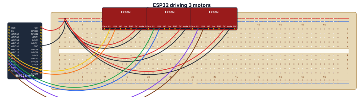
A breadboard wiring diagram for an ESP32 that drives a motor to spin 3 different wheels
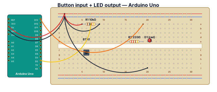
A breadboard wiring diagram for an Arduino Uno reading a button press and lighting an LED: button with pull-down resistor on D2, LED with 220-ohm resistor on D13
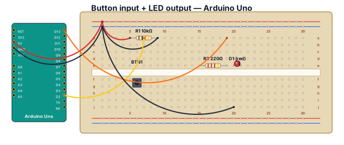
A breadboard wiring diagram for an Arduino Uno reading a button press and lighting an LED: button with pull-down resistor on D2, LED with 220-ohm resistor on D13
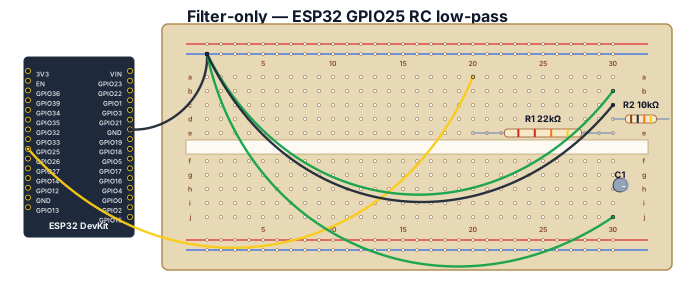
Create a FILTER-ONLY Fritzing-style breadboard close-up. Show one generic ESP32 DevKit on the left and one breadboard. Do NOT include the potentiometer or LCD. Exact placement and wiring: connect ESP32 GND to the breadboard blue ground rail. Connect ESP32 GPIO25 with a yellow jumper to breadboard row 20 on the a-e side. Place R1, 22 kOhm, from row 20 to row 30 on the a-e side, so it is in series with GPIO25. Row 30 is the OUT node. Place R2, 10 kOhm, from row 30 to the blue GND rail. Place C1, polarized electrolytic 10 uF, from row 30 to the blue GND rail, with its positive (+) lead in row 30 and negative (-) lead in the GND rail. Add a clearly labeled green OUT / DUT SIGNAL jumper from row 30. Add DUT GND to the blue ground rail. Use labels GPIO25 PWM, R1 22k, OUT, R2 10k, C1 10uF, capacitor + and -, DUT SIGNAL, DUT GND. Include a red warning label: NEVER CONNECT DUT DIRECTLY TO GPIO25. Ensure every connection follows breadboard row connectivity and do not add any other components or wires.
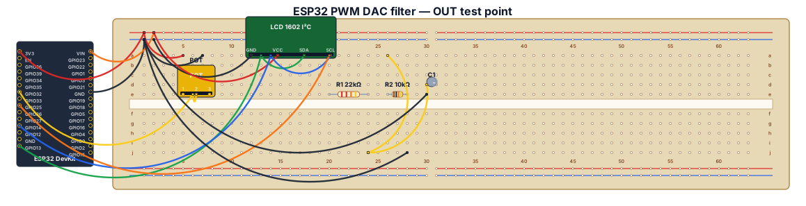
Create a clear Fritzing-style breadboard wiring diagram for a Freenove ESP32 WROVER CAM board (a generic ESP32 DevKit representation is acceptable), a 10k potentiometer, an I2C LCD1602, two resistors, and one polarized electrolytic capacitor. Exact connections: potentiometer outer pins to ESP32 3.3V and GND, center wiper to GPIO32. LCD1602 GND to GND, VCC to 5V, SDA to GPIO13, SCL to GPIO14. Filtered PWM output: GPIO25 connects ONLY to one end of R1 22k ohm; the other end of R1 is the OUT node. From the OUT node connect R2 10k ohm to GND. Also connect C1 10uF electrolytic from OUT to GND, with capacitor positive (+) at OUT and negative (-) at GND. Label OUT as the DUT analog input/test point and connect DUT ground to the common GND rail. Clearly show a common ground rail, resistor values, capacitor polarity, GPIO labels, and emphasize that the DUT must connect to OUT after R1, never directly to GPIO25.
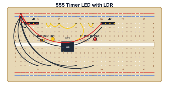
A breadboard wiring diagram with a LDR, 104 capacitor, chip 555 , a led and two jumpers
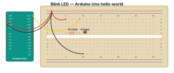
Blink LED hello-world on Arduino Uno with 220-ohm resistor
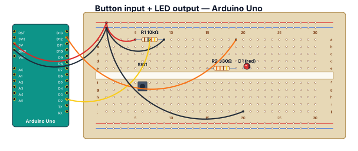
A breadboard wiring diagram for an Arduino Uno R3 reading a button press and lighting an LED: button with pull-down resistor on D2, LED with 330-ohm resistor on D12
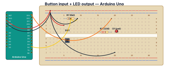
A breadboard wiring diagram for an Arduino Uno reading a button press and lighting an LED: button with pull-down resistor on D2, LED with 220-ohm resistor on D13
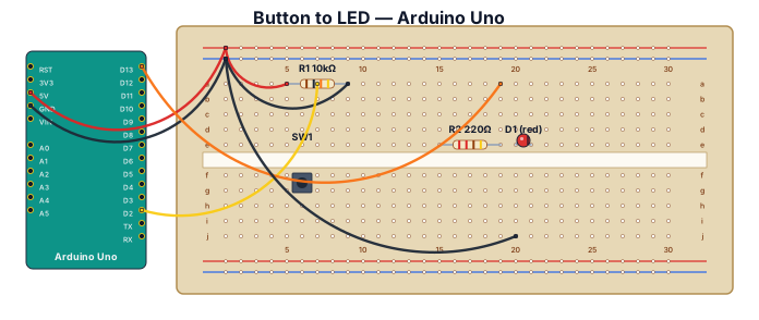
A breadboard wiring diagram for an Arduino UnoQ reading a button press and lighting an LED: button with pull-down resistor on D2, LED with 220-ohm resistor on D13
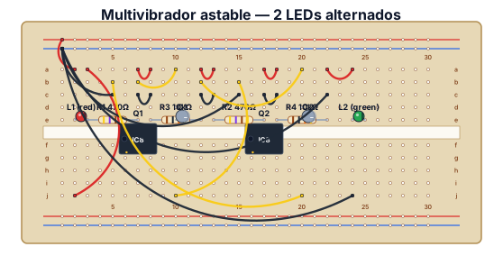
En este circuito se iluminará alternativamente L1 o L2. Los dos transistores trabajan en conmutación es decir cuando uno conduce (saturación) el otro no (corte) y viceversa. Al conectar la alimentación supongamos que L1 se enciende y L2 está apagado, no obstante por L2 circula una muy pequeña corriente (insuficiente para encenderlo) que pasa por R4 atraviesa C2 y llega a la base de Q1, por lo que L1 sigue encendido y C2 cargándose. Cuando C2 esta cargado impide el paso de la corriente, bloquea Q1 y L1 se apaga. Ahora circula una muy pequeña corriente a través de L1 (insuficiente para encenderlo) y R1 hasta la base de Q2 por lo que éste conduce, se enciende L2 y comienza a cargarse C1. Mientras C1 se carga C2 se descarga a través de R3. Después el proceso se repite
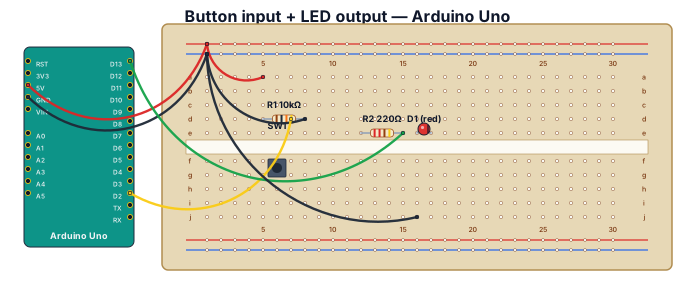
A breadboard wiring diagram for an Arduino Uno reading a button press and lighting an LED: button with pull-down resistor on D2, LED with 220-ohm resistor on D13
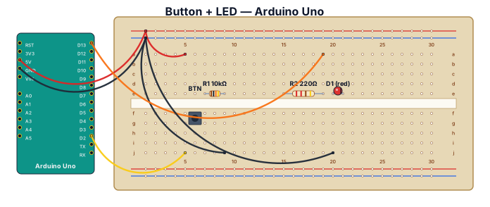
A breadboard wiring diagram for an Arduino Uno reading a button press and lighting an LED: button with pull-down resistor on D2, LED with 220-ohm resistor on D13
Focused examples and prompt ideas
Start with the complete visitor wall above, then use these focused collections when you want a narrower subject and more prompt context.
The first curated collection is being prepared.