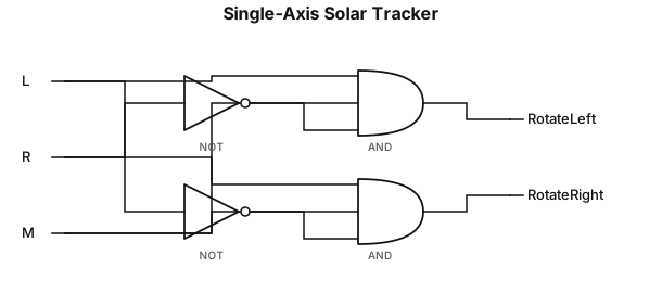
Create a simple single-axis solar tracking logic-gate diagram. Use two light sensors: Left Sensor (L) and Right Sensor (R), plus Motor Enable (M). The motor rotates left when L=1, M=1, and R=0. The motor rotates right when R=1, M=1, and L=0. Use NOT gates to invert the opposite sensor and AND gates to produce Rotate Left and Rotate Right outputs. Use standard logic-gate symbols, black lines, white background, and labels similar to a school engineering schematic.
NODE ARCHIVE · REAL DIAGRAM BRIEFS
Diagram Examples from Real Visitor Prompts
Browse eligible diagrams shared by FreeDiagram visitors, inspect the exact prompts, and build your own version.
Browse 1011 real creationsCOMMUNITY OUTPUTS · EXACT PROMPTS
Logic Gate
Showing 1–9 of 9. No stock examples or system defaults. Choose a tool, study a real result, then reopen its prompt as your starting point.
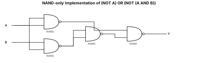
NAND-only implementation of the expression (NOT A) OR (NOT (A AND B))
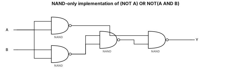
NAND-only implementation of the expression (NOT A) OR NOT(A AND B)
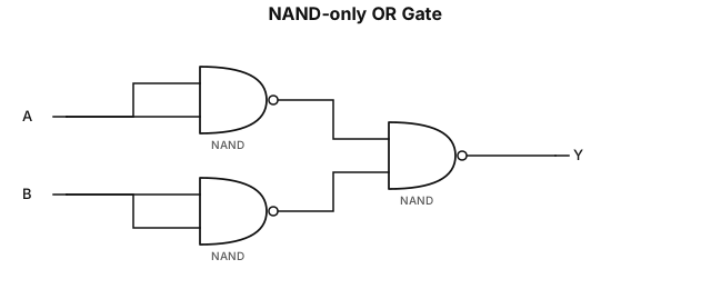
NAND-only implementation of OR gate
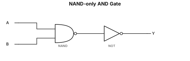
NAND-only implementation of AND gate
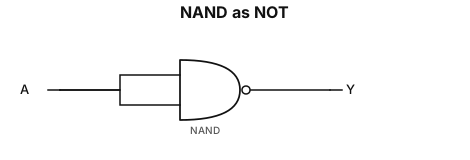
NAND-only implementation of NOT gate
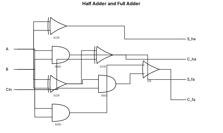
design a half adder and full adder using logic gates
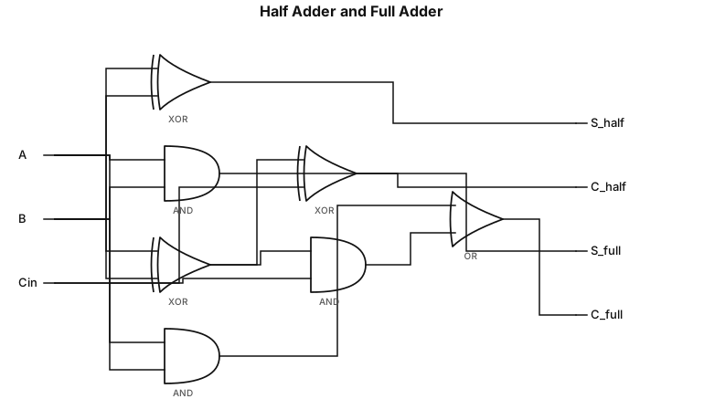
design a half adder abd full adder using logic gates
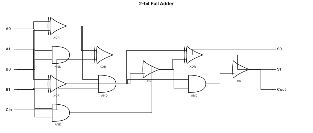
A logic gate circuit for a 2-bit full adder using AND, OR, and XOR gates with inputs A, B, and carry-in, and outputs sum and carry-out
Focused examples and prompt ideas
Start with the complete visitor wall above, then use these focused collections when you want a narrower subject and more prompt context.
The first curated collection is being prepared.