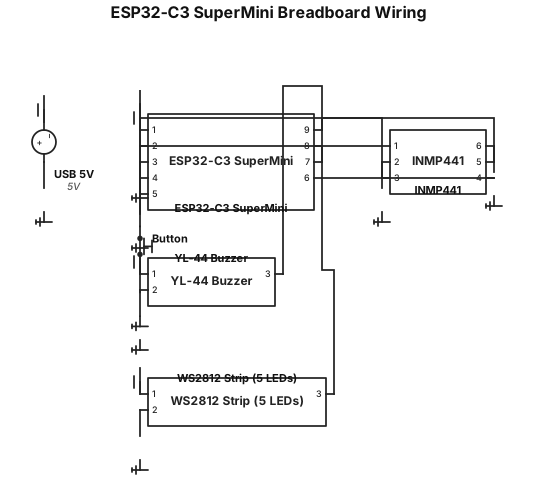
Breadboard wiring, microcontroller ESP32-C3 SuperMini powered via USB 5V. Module 1: INMP441 I2S microphone breakout, 6 pins. VDD to ESP32 3V3. GND to ESP32 GND. SD (data out) to ESP32 GPIO6. WS (word select) to ESP32 GPIO5. SCK (bit clock) to ESP32 GPIO4. L/R to ESP32 GND for left channel. Module 2: YL-44 active buzzer module, 3 pins. VCC to ESP32 VIN 5V. GND to ESP32 GND. IO trigger to ESP32 GPIO10. Module 3: WS2812 addressable LED strip with 5 LEDs in a row. 5V to ESP32 VIN. GND to ESP32 GND. DIN to ESP32 GPIO7. Module 4: momentary push button, 2 legs. One leg to ESP32 GPIO3 with internal pull-up, other leg to ESP32 GND. Wire colors: red for 5V and 3V3 power, black for ground, yellow for I2S signals SD WS SCK, orange for buzzer trigger GPIO10, green for LED data GPIO7, blue for button GPIO3.
Diagram Examples from Real Visitor Prompts
Browse eligible diagrams shared by FreeDiagram visitors, inspect the exact prompts, and build your own version.
Browse 1011 real creationsCircuit Diagrams
Showing 1–24 of 50. No stock examples or system defaults. Choose a tool, study a real result, then reopen its prompt as your starting point.
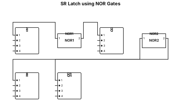
Draw a simple SR latch circuit diagram using logic gates
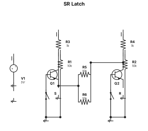
Draw a simple SR latch circuit diagram
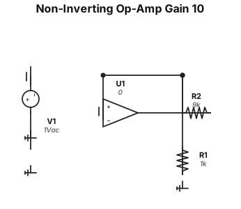
A non-inverting op-amp amplifier with a gain of 10 using a 1 kΩ and 9 kΩ resistor
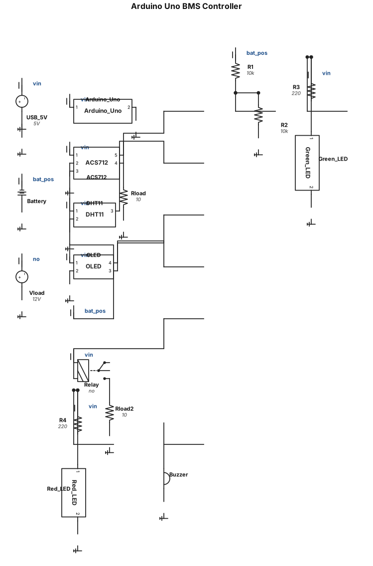
The Arduino Uno, powered through a USB connection, acts as the central controller of the Battery Management System (BMS). Its 5V and GND pins supply power to all the modules through the breadboard power rails. The battery voltage is monitored using a voltage divider made of two 10 kΩ resistors connected to analog pin A1, while the ACS712 current sensor is powered by the Arduino and connected to analog pin A0, with the load connected in series through its IP+ and IP− terminals to measure current. The DHT11 temperature sensor is connected to digital pin D2 to monitor battery temperature. An I2C OLED display is connected to pins A4 (SDA) and A5 (SCL) to display real-time voltage, current, temperature, and system status. A relay module connected to digital pin D7 disconnects the load during fault conditions, while a green LED (D9) indicates normal operation, a red LED (D8) indicates faults, and a buzzer (D10) provides an audible alarm whenever over-current, under-voltage, or over-temperature conditions are detected.
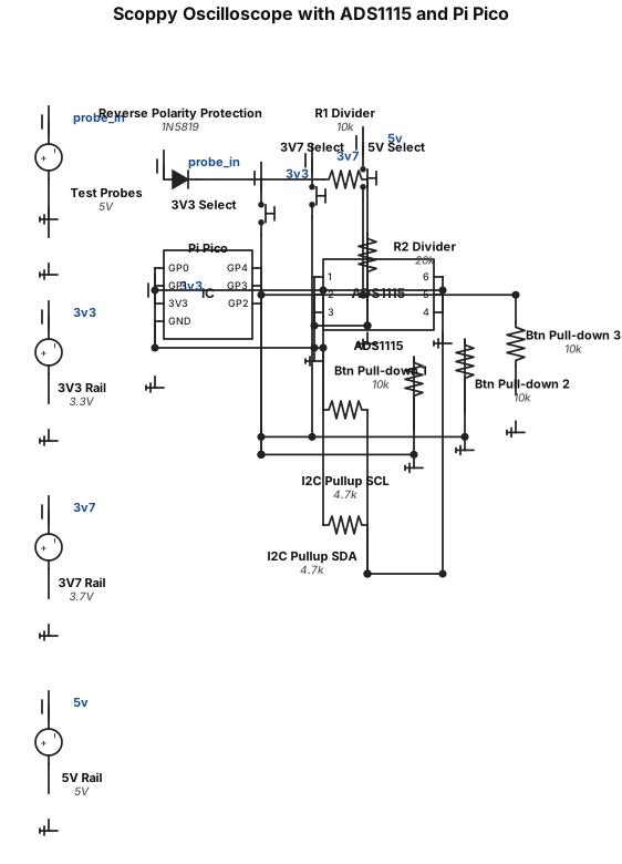
Create a diagram for a Scoppy oscilloscope using an ADS1115 and a Raspberry Pi Pico to mesure 3v3, 3.7v and 5v from one single set of test hook probes. It needs reverse polarity protection and a voltage divider for the 5V input; it also needs 3 buttons to be able to switch between the 3 different voltages when testing.
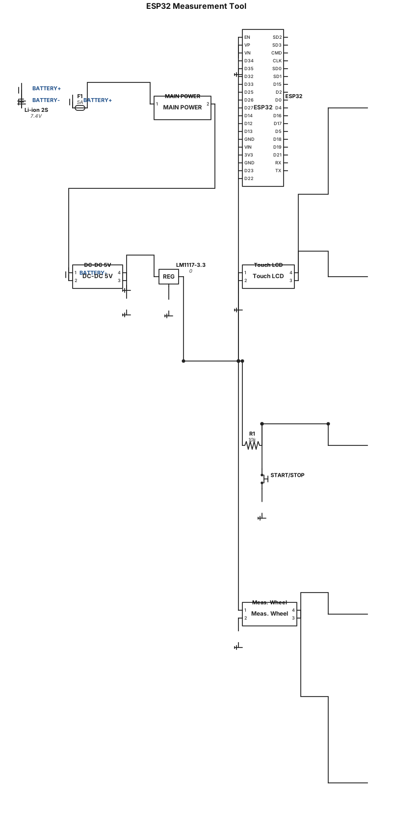
Create a clean, minimal, and professional electronic block diagram and netlist for a microcontroller-based measurement tool. System Components: 1. Power Subsystem: Rechargeable battery connected to a 5A fuse, a main DPST power switch, a DC-DC buck converter (stepping down to 5V), and a 3.3V voltage regulator (LM1117-3.3). 2. Processing Core: ESP32 microcontroller powered by 3.3V/5V with properly routed ground (GND) planes. 3. User Interface: Touchscreen LCD connected via I2C (SDA, SCL) and a Start/Stop push button with a pull-up resistor. 4. Measurement Subsystem: Rotary encoder connected to a mechanical measuring wheel, outputting dual quadrature signals (A and B channels) directly to designated ESP32 digital GPIO pins. Output Format: Provide a structured, text-based pin mapping table and schematic connection guide detailing every net name (BATTERY+, BATTERY-, VCC, GND, 3.3V, 5V, SDA, SCL, A, B, BUTTON, and GPIO pins) suitable for importing into an electronic design layout or documentation file.
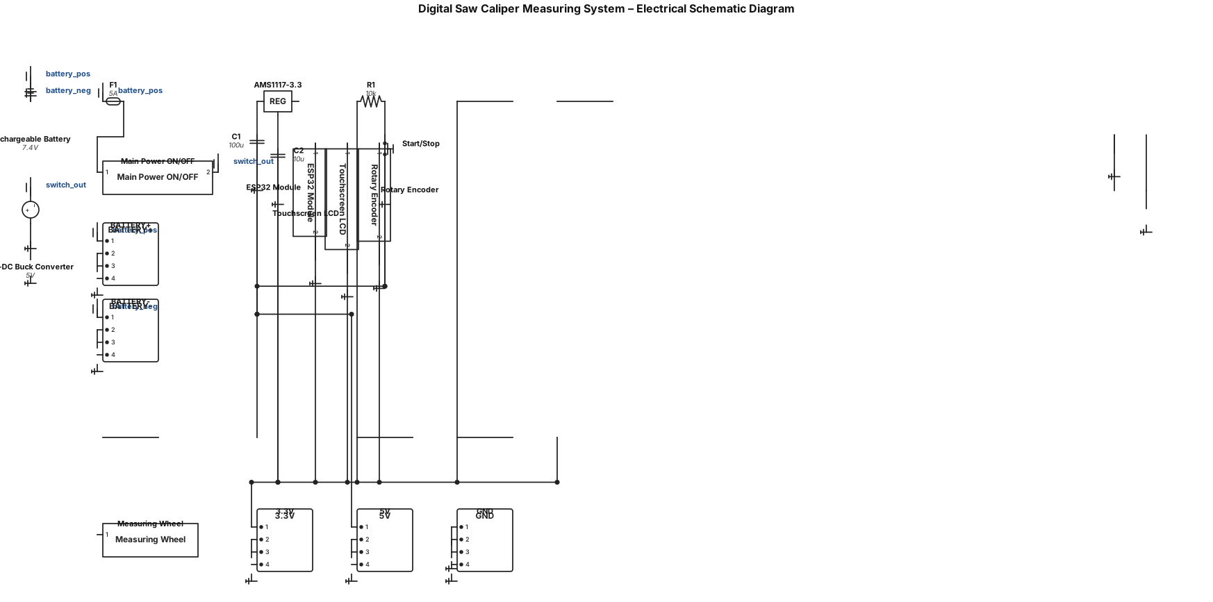
A professional, high-resolution technical electrical schematic diagram for a Digital Saw Caliper Measuring System, designed for engineering prototype documentation. Rendered in a clean black-and-white engineering blueprint style with standard electronic component symbols, solid black wiring lines, and a white background. Layout & Structure: - Title at the top: DIGITAL SAW CALIPER MEASURING SYSTEM – ELECTRICAL SCHEMATIC DIAGRAM - Left side: Rechargeable battery connected through a 5A fuse and a DPST main power ON/OFF switch, feeding into a DC-DC buck converter (stepping down to 5V) and an AMS1117-3.3 voltage regulator (stepping down to 3.3V). - Center: An ESP32 microcontroller module with properly routed VCC (3.3V/5V), GND planes, and GPIO pins. - Connected Peripherals: - A touchscreen LCD connected via I2C (SDA, SCL) and power lines. - A start/stop push button with a pull-up resistor connected to a GPIO pin. - A rotary encoder connected to a measuring wheel, with clear A and B quadrature signal lines routed to designated ESP32 GPIO pins. - Right side: A detailed "Symbols and Components Legend" box containing standard icons for Battery, Power Switch, Button, Touchscreen LCD, Rotary Encoder, Measuring Wheel, Voltage Regulator, Fuse, Connector, VCC, and GND. Style Notes: Crisp vector lines, sharp text labels for all pins and nets (BATTERY+, BATTERY-, VCC, GND, 3.3V, 5V, SDA, SCL, GPIO, A, B, BUTTON), clean orthogonal wire routing with junction dots, and no cartoon elements.
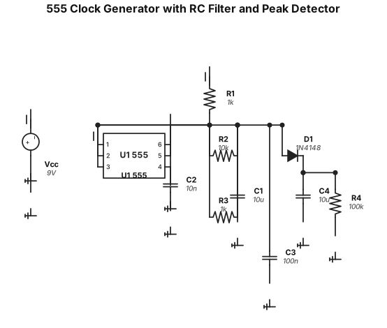
таймер 555 в роли тактового генератора. с выхода генератора на rc фильтр, а после на пиковый детектор
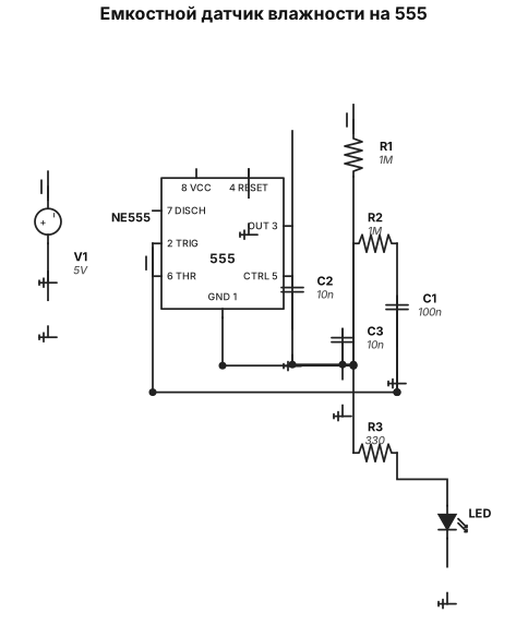
емкостной датчик влажности на 555 таймере
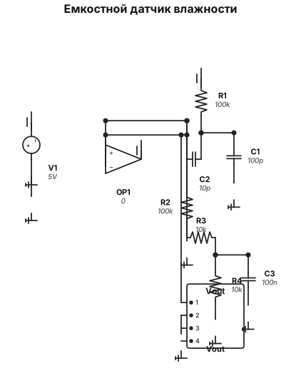
емкостной датчик влажности
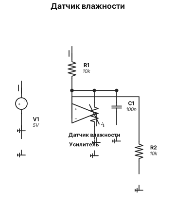
датчик влажности
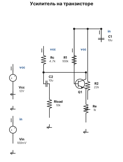
усилитель на транзисторе
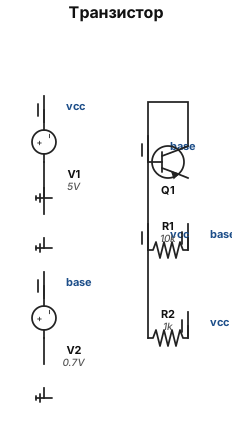
транзистор
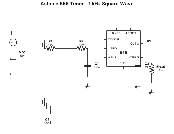
An astable 555 timer circuit producing a 1 kHz square wave
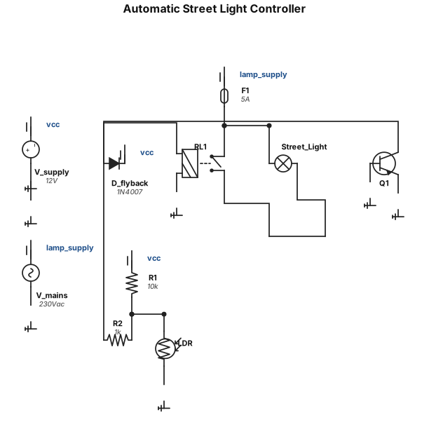
Create a schematic for an automatic street light controller using an LDR, resistor voltage divider, NPN transistor, relay, flyback diode and DC power supply. The relay contacts control an LED lamp/street light. Use standard electronic symbols, clearly label every component and show all electrical connections.
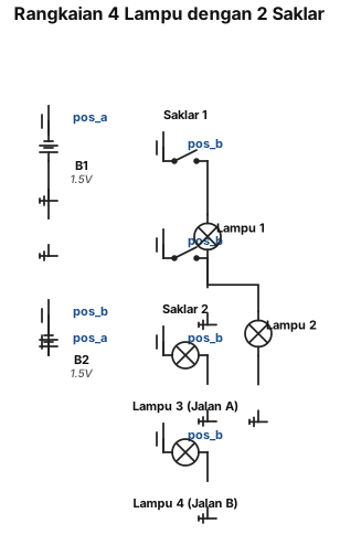
4 lampu pijar 2 saklar tunggal 2 lampu pijar berhubungan dengan 2 sakral tunggal secara masing masing dan lampu yang 2 lagi ditempatkan di jalan yang berbeda Sumber tegangannya menggunakan 2 buah batu baterai Gambarkan rangkaian paralel dan seri yang rapih
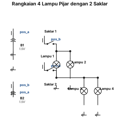
4 lampu pijar 2 saklar tunggal 2 lampu pijar berhubungan dengan 2 sakral tunggal secara masing masing dan lampu yang 2 lagi ditempatkan di jalan yang berbeda Sumber tegangannya menggunakan 2 buah batu baterai Gambarkan rangkaian paralel dan seri
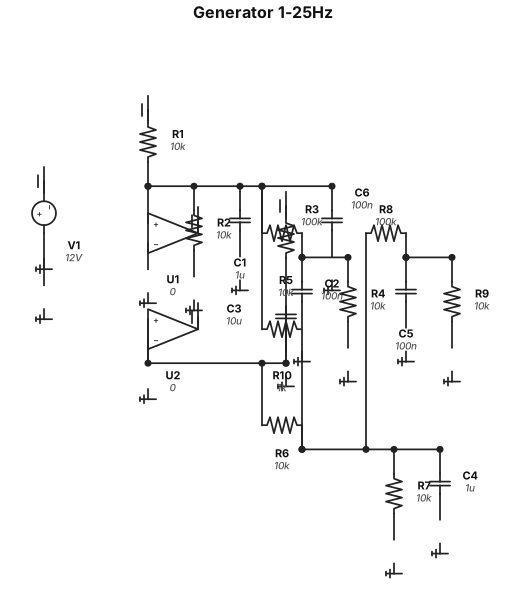
schemat generatora w zakresie od 1-25Hz
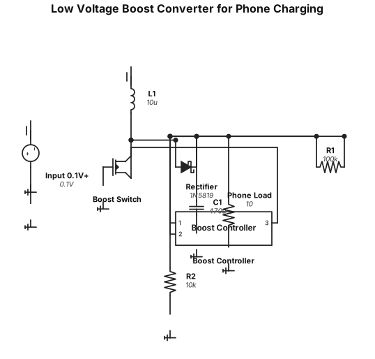
I need a circuit to boost voltage from 0.1 volts or higher to a certain volts so I can charge a phone It's easy
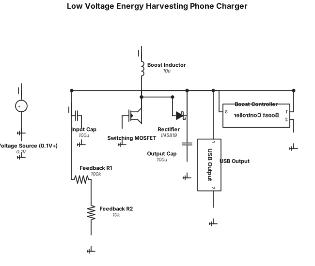
I need a circuit to boost voltage from 0.1 volts or higher to a certain volts so I can charge a phone.
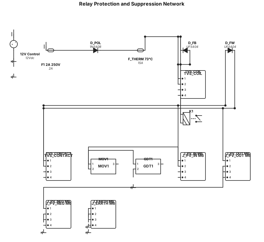
🎛️ Optimized Component Value MatrixSub-CircuitComponent ReferenceValue / RatingComponent Selection Rule / Part Number Example12V Control InputF12A 250VCeramic Quick-Blow Fuse (5x20mm standard).Polarity ProtectionD_POL1000V, 3A1N5408 Standard Recovery Diode (handles 12V inrush with negligible forward drop).Coil Transient Sup.D_FB + TVS_COILUF5404 (400V, 3A Ultra-Fast) + SMAJ18A (18V Uni-directional TVS)Connected in series across the coil. Accelerates relay armature drop-out time to reduce 48V contact arcing.Thermal ProtectionF_THERM73°C, 15A DCThermal cut-off fuse mechanically clamped/epoxied directly onto the relay housing.Contact Arc MitigationD_FW + TVS_CONTACTSUF5404 + 5KP54A (5000W TVS)Placed directly across the relay contacts. Dissipates inductive energy during emergency disconnects.Surge ProtectionMOV1 + GDT1560V MOV (Littelfuse V571BA40) + 90V GDTPlaced in series between the +48V PV Rail and Chassis Earth M6 Stud (J_EARTH) to prevent leakage current while stopping lightning surges.PCB Terminals (High Amp)J_PV_IN, J_PV_OUT, J_PV_NEG_...M6 Threaded StudWurth Elektronik WP-SMSH M6 (7460309) SMT/Through-Hole heavy terminal rated >50A.
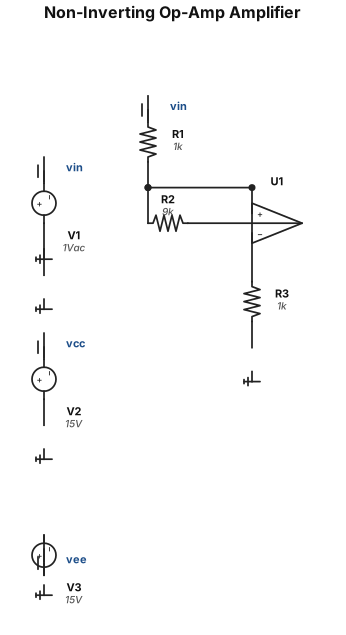
A non-inverting op-amp amplifier circuit with a gain of 10, using a 1 kΩ input resistor and a 9 kΩ feedback resistor
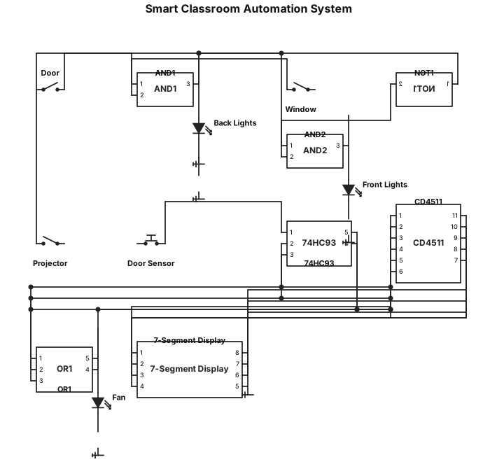
Here is a prompt you can copy and paste directly into an AI diagram generator. It focuses on the core logic and functional flow without overwhelming the AI with minor breadboard details. Copy and paste the text below: System Prompt: Generate a clear, well-organized digital circuit schematic for a "Smart Classroom Automation System." Do not include minor components like pull-down/current-limiting resistors or power supply rails; focus strictly on the logical connections between the inputs, ICs, and outputs. Inputs (Left Side): 3 Slide Switches labeled: "Door", "Window", "Projector" 1 Push Button labeled: "Door Sensor" Processing Logic (Middle): AND Gate (2-input) NOT Gate (Inverter) OR Gate (4-input equivalent) 74HC93 (4-bit Binary Counter) CD4511 (BCD to 7-Segment Decoder) Outputs (Right Side): LED labeled: "Back Lights" LED labeled: "Front Lights" LED labeled: "Fan" 1 Single-Digit 7-Segment Display Connections to draw: Back Lights: Wire the "Door" and "Window" switches into an AND gate. Connect the output of this AND gate to the "Back Lights" LED. Front Lights: Wire the "Projector" switch into a NOT gate. Wire the output of the first AND gate (Door & Window) and the output of the NOT gate into a second AND gate. Connect this output to the "Front Lights" LED. Counting System: Wire the "Door Sensor" push button to the clock input of the 74HC93 Counter. Display: Wire the 4-bit binary output of the 74HC93 Counter into the inputs of the CD4511 Decoder. Wire the 7 output lines of the Decoder to the 7-Segment Display. Fan Automation: Wire the same 4-bit binary output from the 74HC93 Counter into the OR Gate. Wire the output of the OR Gate to the "Fan" LED.
Focused examples and prompt ideas
Start with the complete visitor wall above, then use these focused collections when you want a narrower subject and more prompt context.
The first curated collection is being prepared.