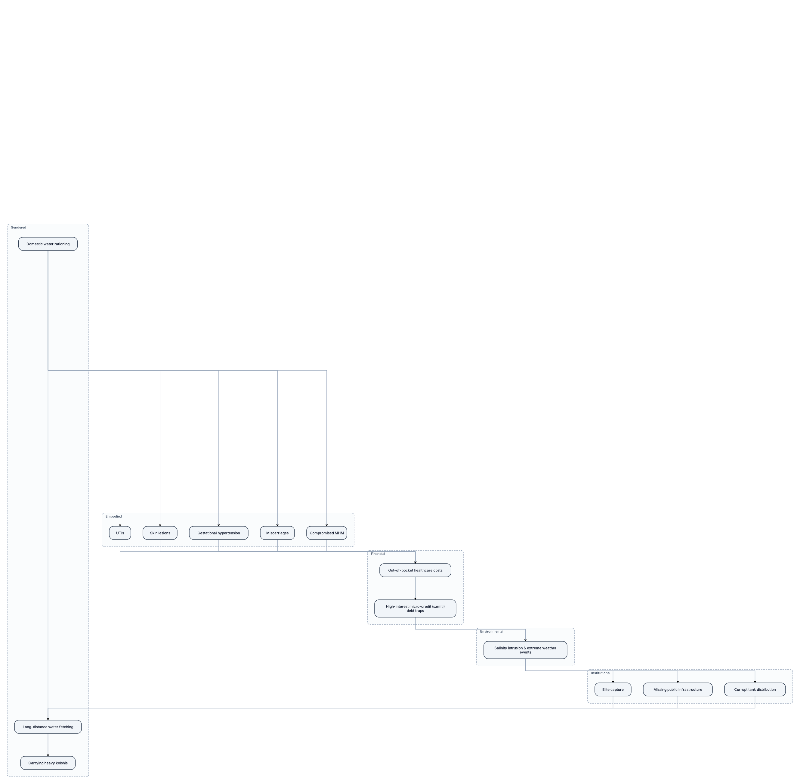
Figure 1: The Multi-Dimensional Cycle of Climate-Induced Gender VulnerabilityWhere to place it: At the end of Section 6.1 (Introduction) or the beginning of Section 6.2 (Spatial & Gendered Embodiment).Purpose: Serves as the overarching conceptual map for the entire chapter. It visually introduces the reader to how macro environmental drivers trickle down through institutional gaps to create bodily harms. Visual Format: A top-down or cyclical Flowchart / System Dynamics Diagram.What it shows:Environmental Trigger: Salinity intrusion & extreme weather events. Institutional Gatekeeping: Elite capture, missing public infrastructure, corrupt tank distribution. Gendered Labor: Long-distance water fetching, carrying heavy kolshis, domestic water rationing. Embodied Health Harms: UTIs, skin lesions, gestational hypertension, miscarriages, compromised MHM. Financial Exhaustion: Out-of-pocket healthcare costs, high-interest micro-credit (samiti) debt traps.
Diagram Examples from Real Visitor Prompts
Browse eligible diagrams shared by FreeDiagram visitors, inspect the exact prompts, and build your own version.
Browse 3322 real creationsAll visitor creations
Showing 2569–2592 of 3322. No stock examples or system defaults. Choose a tool, study a real result, then reopen its prompt as your starting point.
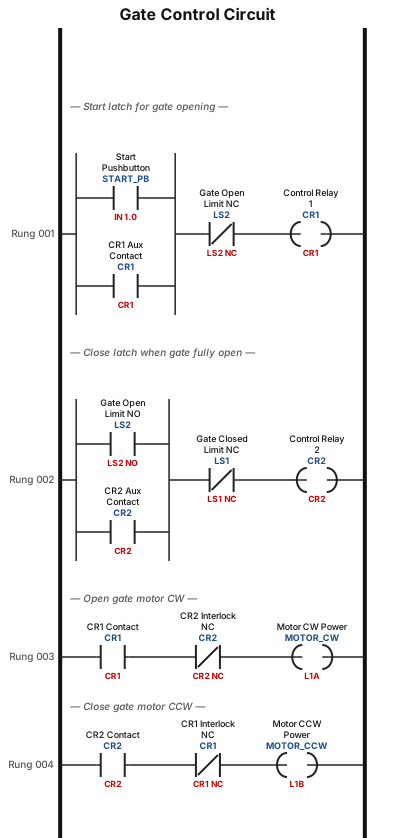
A reversible motor is used to open and close a gate. The motor has three terminals: L1A, L1B, and L2. When L2 is connected to the ground and power is applied to L1A, the motor runs clockwise, CW, direction, opening the gate. When power is applied to L1B, the motor runs counterclockwise, CCW, direction, closing the gate. The gate has two limit switches: LS1 is activated when the gate is closed, and LS2 is activated when the gate is open. Each limit switch has one normally open. NO, contact and one normally closed, NC, contact. Two control relays, CR1 and CR2, are used in the gate control circuit. These relays have two NO contacts and two NC contacts. A NO pushbutton START switch is used to initiate the opening of the gate. Draw a ladder diagram that will open the gate after a momentary closure of the START switch, close the gate immediately after the gate is fully open, and turn OFF the power to the motor when the gate is closed. Your circuit must include an interlock feature that will not allow simultaneous application of power on L1A and L1B.
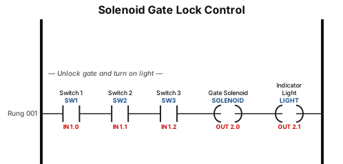
A solenoid-operated lock is used on the gate of an enclosed storage area. When the solenoid is activated, the gate is unlocked, and a light goes ON. Three pushbutton switches are used in the solenoid control circuit, SW1, SW2, and SW3. The three switches are located such that a single operator can close only one switch at a time, two operators are required to close two switches, and three operators are required to close all three switches.
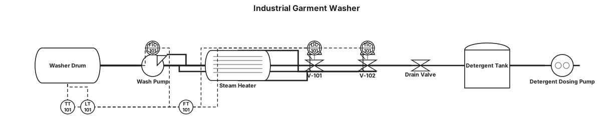
industrial washer used in garments
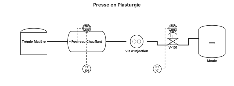
une presse en plastrugie
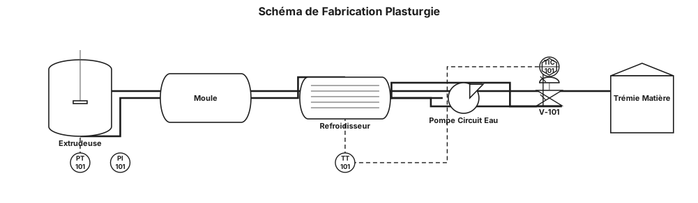
schéma de process ( schéma de fabrication) en industrie de la plasturgie
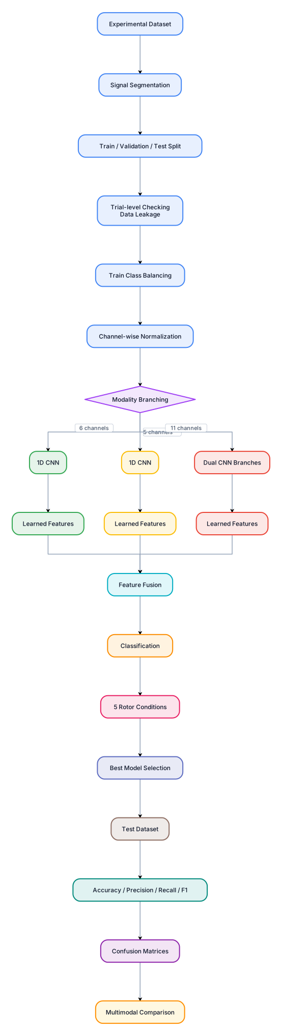
EXPERIMENTAL DATASET │ ↓ Signal Segmentation │ ↓ Train / Validation / Test │ ↓ Trial-level checking (Data leakage) │ ↓ Train Class Balancing │ ↓ Channel-wise Normalization │ ┌───────────┼───────────┐ ↓ ↓ ↓ ELECTRICAL VIBRATION FUSION 6 channels 5 channels 11 channels │ │ │ ↓ ↓ ↓ 1D CNN 1D CNN Dual CNN │ │ branches │ │ │ ↓ ↓ ↓ Learned features Learned features │ │ │ └───────────┼───────────┘ ↓ Classification ↓ 5 Rotor Conditions │ ↓ Best Model Selection │ ↓ TEST DATASET │ ↓ Accuracy / Precision / Recall / F1 │ ↓ Confusion Matrices │ ↓ Multimodal Comparison donne moi uen belle image represntative de cet architecture stp donne la moi en anglais , l'mage est trop petit je veux quelque chose de beau avec desd dessin , pour une revuie ieee
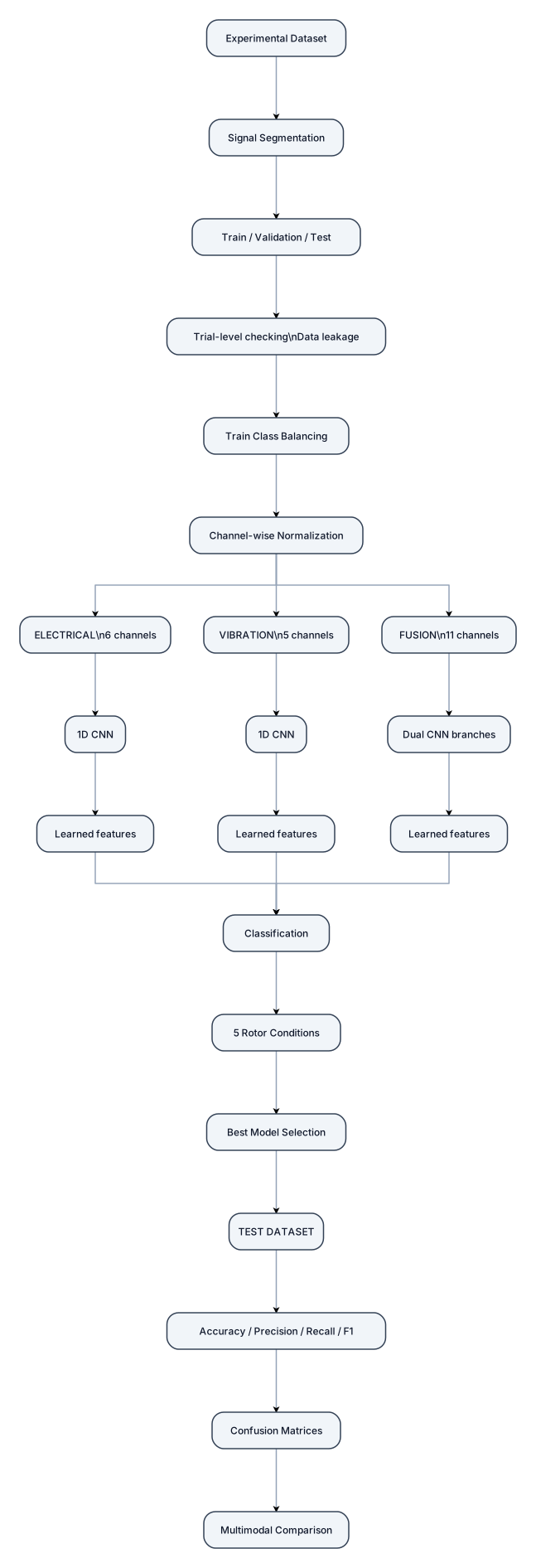
EXPERIMENTAL DATASET │ ↓ Signal Segmentation │ ↓ Train / Validation / Test │ ↓ Trial-level checking (Data leakage) │ ↓ Train Class Balancing │ ↓ Channel-wise Normalization │ ┌───────────┼───────────┐ ↓ ↓ ↓ ELECTRICAL VIBRATION FUSION 6 channels 5 channels 11 channels │ │ │ ↓ ↓ ↓ 1D CNN 1D CNN Dual CNN │ │ branches │ │ │ ↓ ↓ ↓ Learned features Learned features │ │ │ └───────────┼───────────┘ ↓ Classification ↓ 5 Rotor Conditions │ ↓ Best Model Selection │ ↓ TEST DATASET │ ↓ Accuracy / Precision / Recall / F1 │ ↓ Confusion Matrices │ ↓ Multimodal Comparison donne moi uen belle image represntative de cet architecture stp donne la moi en anglais
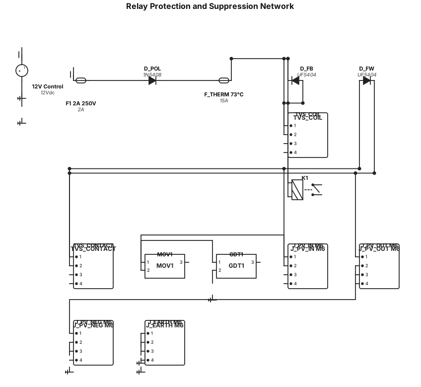
🎛️ Optimized Component Value MatrixSub-CircuitComponent ReferenceValue / RatingComponent Selection Rule / Part Number Example12V Control InputF12A 250VCeramic Quick-Blow Fuse (5x20mm standard).Polarity ProtectionD_POL1000V, 3A1N5408 Standard Recovery Diode (handles 12V inrush with negligible forward drop).Coil Transient Sup.D_FB + TVS_COILUF5404 (400V, 3A Ultra-Fast) + SMAJ18A (18V Uni-directional TVS)Connected in series across the coil. Accelerates relay armature drop-out time to reduce 48V contact arcing.Thermal ProtectionF_THERM73°C, 15A DCThermal cut-off fuse mechanically clamped/epoxied directly onto the relay housing.Contact Arc MitigationD_FW + TVS_CONTACTSUF5404 + 5KP54A (5000W TVS)Placed directly across the relay contacts. Dissipates inductive energy during emergency disconnects.Surge ProtectionMOV1 + GDT1560V MOV (Littelfuse V571BA40) + 90V GDTPlaced in series between the +48V PV Rail and Chassis Earth M6 Stud (J_EARTH) to prevent leakage current while stopping lightning surges.PCB Terminals (High Amp)J_PV_IN, J_PV_OUT, J_PV_NEG_...M6 Threaded StudWurth Elektronik WP-SMSH M6 (7460309) SMT/Through-Hole heavy terminal rated >50A.
![Phylogenetic Tree example: { "name": "Vertebral column", "children": [ { "name": "Fish" }, { "name": "Four limbs (tetrapods)", "children": [ { "name": "Amphibians" }, { "name":](https://psvtykrtciekraoilfux.supabase.co/storage/v1/object/public/gallery-assets/freediagram/feed/1ac29f40-20b5-49cd-b749-fda42b7af07d.svg)
{ "name": "Vertebral column", "children": [ { "name": "Fish" }, { "name": "Four limbs (tetrapods)", "children": [ { "name": "Amphibians" }, { "name": "Amniotic egg", "children": [ { "name": "Mammals (hair, mammary glands)" }, { "name": "Scaly skin (reptile lineage)", "children": [ { "name": "Reptiles" }, { "name": "Birds (feathers)" } ] } ] } ] } ] }
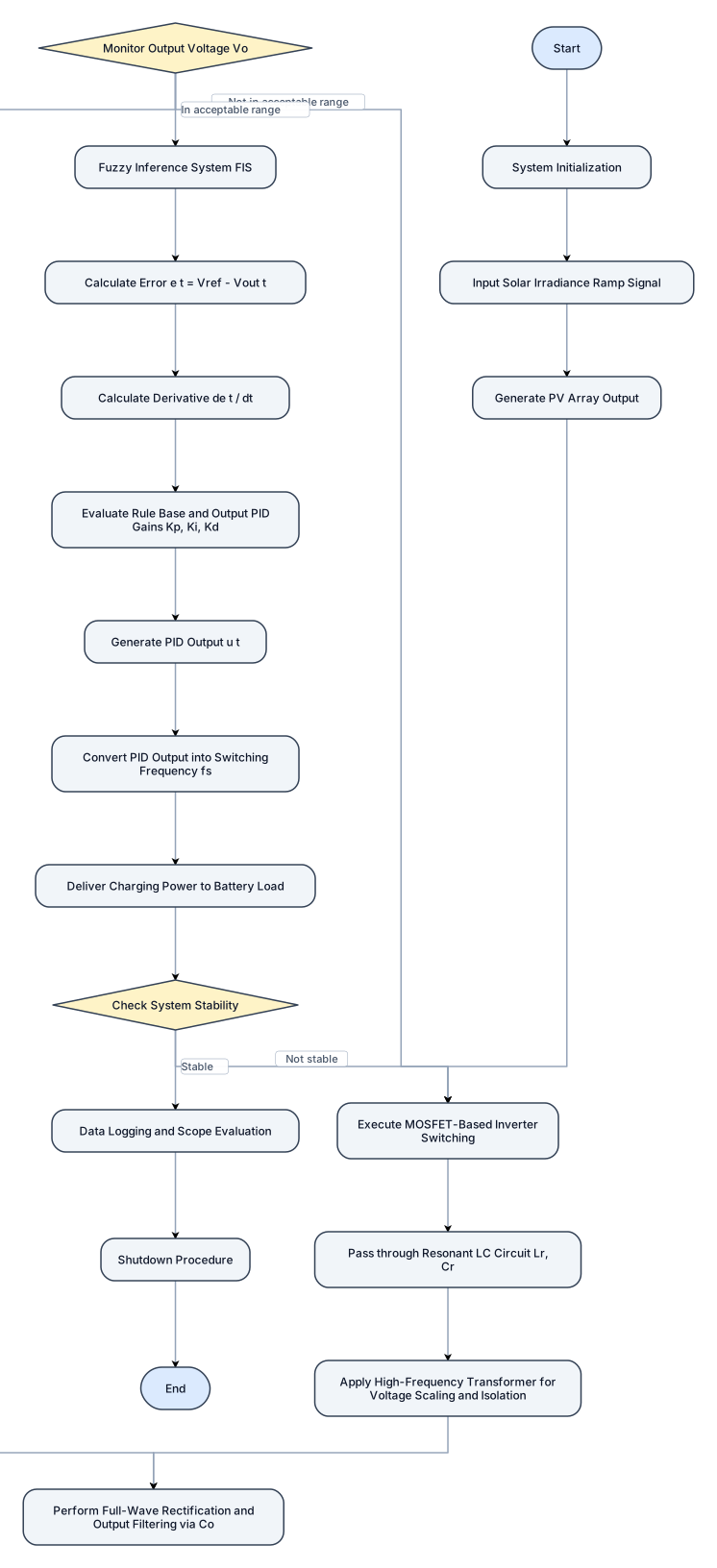
Input: PV Array Output, Reference Voltage Vref Output: Regulated Charging Voltage Vout, Stable Battery Charging Power Begin Control Algorithm: Start System Initialization Input Solar Irradiance (Ramp Signal) Generate PV Array Output Begin Power Conversion: Execute MOSFET-Based Inverter Switching Pass through Resonant LC Circuit: Lr,Cr Apply High-Frequency Transformer for Voltage Scaling and Isolation Perform Full-Wave Rectification and Output Filtering via Co Monitor Output Voltage Vo: If Vo is not within the acceptable range: Return to Inverter Switching and repeat Else Continue to Controller Phase Fuzzy Inference System (FIS): Calculate Error: e(t) = Vref − Vout(t) Calculate Derivative: ∆e(t) = de(t) dt Evaluate Rule Base and Output PID Gains: Kp,Ki,Kd Generate PID Output: Use PID Equation: u(t) = Kpe(t)+Ki t 0 e(τ)dτ+Kd de(t) Convert PID Output into Switching Frequency fs Deliver Charging Power to Battery Load Check System Stability: If System is Stable: Proceed to Data Logging Else Loop back to Step 4 for Adjustment Data Logging and Scope Evaluation Shutdown Procedure End

A fishbone diagram analysing why checkout conversion dropped 18% last week: categories for Code, Infrastructure, UX, and Payment
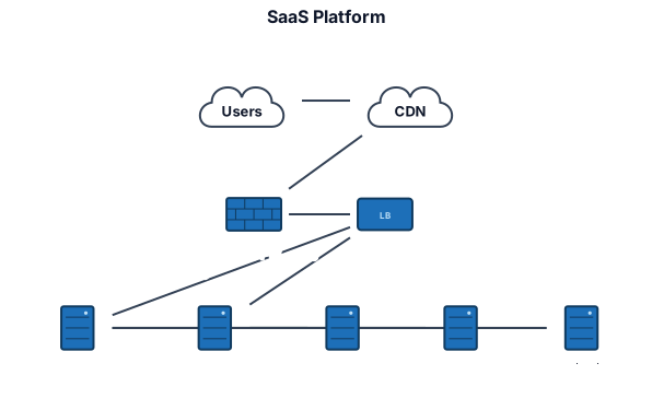
A network diagram for a small SaaS platform with users, CDN, load balancer, two app servers, private database, cache, and monitoring
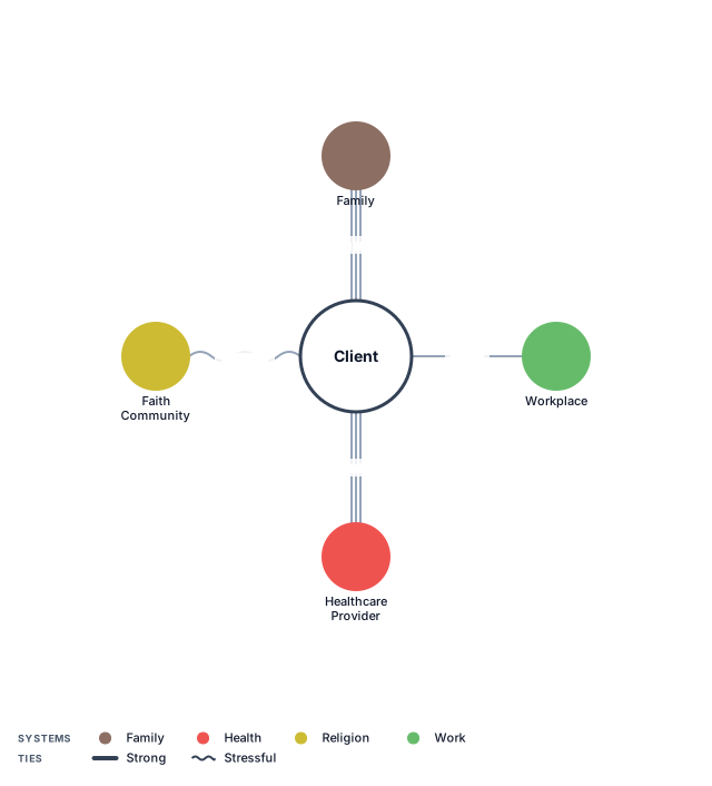
An ecomap of a client's support network: family, work, healthcare, and faith community, with strong and stressful ties
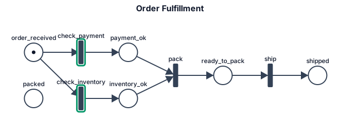
A Petri net for order fulfillment with payment and inventory checks converging before packing and shipment
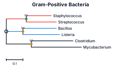
tree for gram positive into cocci and bacilli into staph and strep and so on
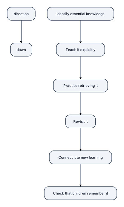
Identify essential knowledge → teach it explicitly → practise retrieving it → revisit it → connect it to new learning → check that children remember it.
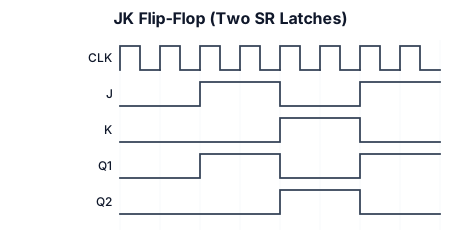
A timing diagram for an JK flip flop designed using two SR latches. show clk, J,K ,the output of the first latch, and the output of the second latch.
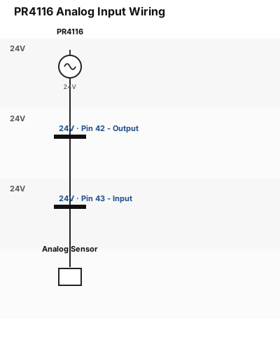
I got an PR4116, with an analog input on pin 42 and 43 with pin 42 of the pr is the output en pin 42 is then input from the sensor
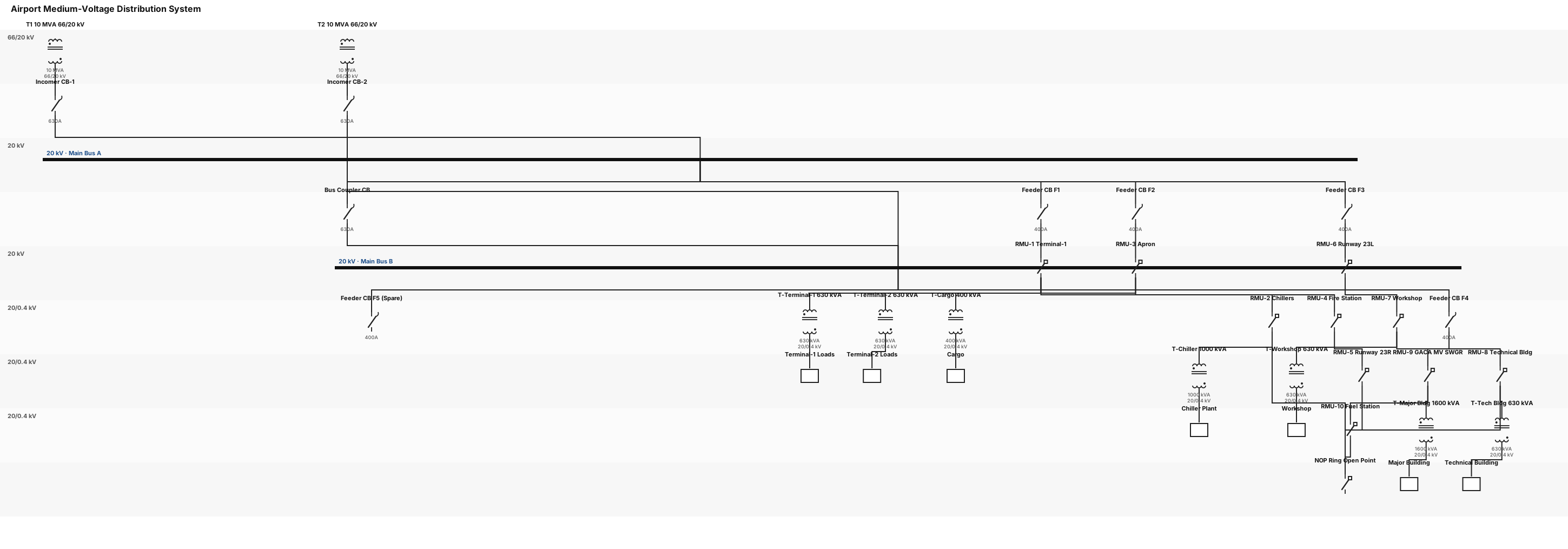
Plain Text 1 Create a medium-voltage single-line diagram for an airport power distribution system. 2 3 Source: 4 - Two 10 MVA, 66/20 kV power transformers operating in parallel. 5 - 20 kV main switchboard with bus coupler. 6 7 Outgoing feeders: 8 - F1 feeding Terminal-1 and Chillers through RMUs. 9 - F2 feeding Apron, Fire Station, and Runway 23R through RMUs. 10 - F3 feeding Runway 23L, Workshop, and Technical Building through RMUs. 11 - F4 feeding GACA MV Switchgear and Fuel Station through RMUs. 12 - F5 spare feeder. 13 14 Distribution transformers: 15 - Terminal loads: 630 kVA transformers. 16 - Chiller plant: 1000 kVA transformer. 17 - Cargo: 400 kVA transformer. 18 - Technical facilities: 630 kVA transformers. 19 - Major building load: 1600 kVA transformer. 20 21 Show: 22 - MV switchgear incomers. 23 - Busbar arrangement. 24 - Feeder circuit breakers. 25 - RMUs. 26 - Distribution transformers. 27 - Normally open point in the ring network. 28 - All equipment labels and transformer ratings.
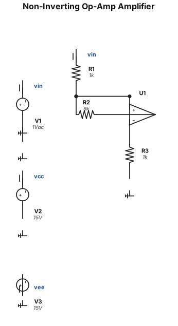
A non-inverting op-amp amplifier circuit with a gain of 10, using a 1 kΩ input resistor and a 9 kΩ feedback resistor
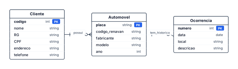
Construir um modelo de entidades e relacionamentos (MER) para uma companhia de seguros de automóveis com um conjunto de clientes, onde cada um possui um certo número de automóveis. Os dados do cliente são código, nome, RG, CPF, endereço e telefone. Do carro deve-se armazenar a placa, código RENAVAN, fabricante, modelo e ano. Associado a cada automóvel há um histórico de ocorrências. Cada ocorrência deve ter um número (único), data, local e descrição.
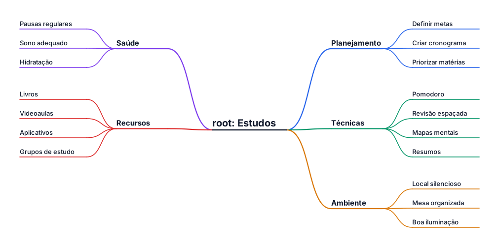
estudos
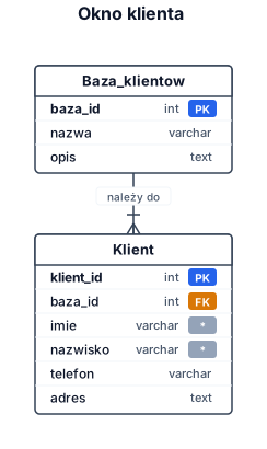
Utwórz okno klient. Dla klienta zapisywane są Imię, Nazwisko, Telefon, adres Klienta podłącz do Baza klientów