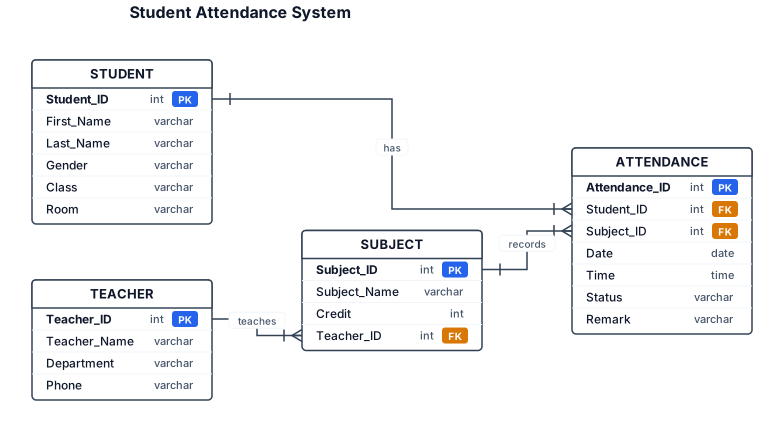
Create an ERD for a Student Attendance System. STUDENT(Student_ID PK, First_Name, Last_Name, Gender, Class, Room) TEACHER(Teacher_ID PK, Teacher_Name, Department, Phone) SUBJECT(Subject_ID PK, Subject_Name, Credit, Teacher_ID FK) ATTENDANCE(Attendance_ID PK, Student_ID FK, Subject_ID FK, Date, Time, Status, Remark) Relationships: TEACHER 1:N SUBJECT STUDENT 1:N ATTENDANCE SUBJECT 1:N ATTENDANCE Show all PKs, FKs, attributes, and cardinalities.
NODE ARCHIVE · REAL DIAGRAM BRIEFS
Diagram Examples from Real Visitor Prompts
Browse eligible diagrams shared by FreeDiagram visitors, inspect the exact prompts, and build your own version.
Browse 3327 real creationsCOMMUNITY OUTPUTS · EXACT PROMPTS
All visitor creations
Showing 2785–2808 of 3327. No stock examples or system defaults. Choose a tool, study a real result, then reopen its prompt as your starting point.
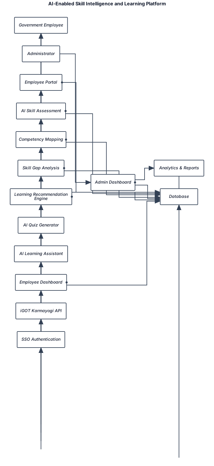
Create a system architecture diagram for an AI-enabled Skill Intelligence and Learning Platform. Actors: - Government Employee - Administrator Core Modules: - Employee Portal - AI Skill Assessment - Competency Mapping - Skill Gap Analysis - Learning Recommendation Engine - AI Quiz Generator - AI Learning Assistant - Employee Dashboard - Admin Dashboard External Integrations: - iGOT Karmayogi API - SSO Authentication Storage: - Database Flow: Employee -> Portal -> AI Assessment -> Skill Gap Analysis -> Learning Recommendation -> iGOT Courses -> Dashboard Admin -> Dashboard -> Analytics -> Reports
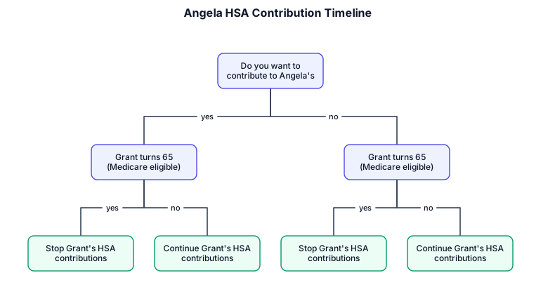
A decision tree that starts with "Do you want to contribute to Angela's HSA when Grant reaches 65. Paths are "Yes" and "No", after answering that the next part of the diagram will be timelines with dates and actions

Diagrama espina de pescado para la incertidumbre en la concentración de una solución patrón que se realiza partiendo del reactivo sólido

A fishbone diagram analysing why our checkout conversion dropped 18% last week

Ishikawa scheme
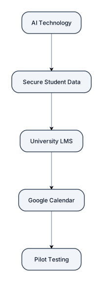
AI Technology ↓ Secure Student Data ↓ University LMS Google Calendar ↓ Pilot Testing
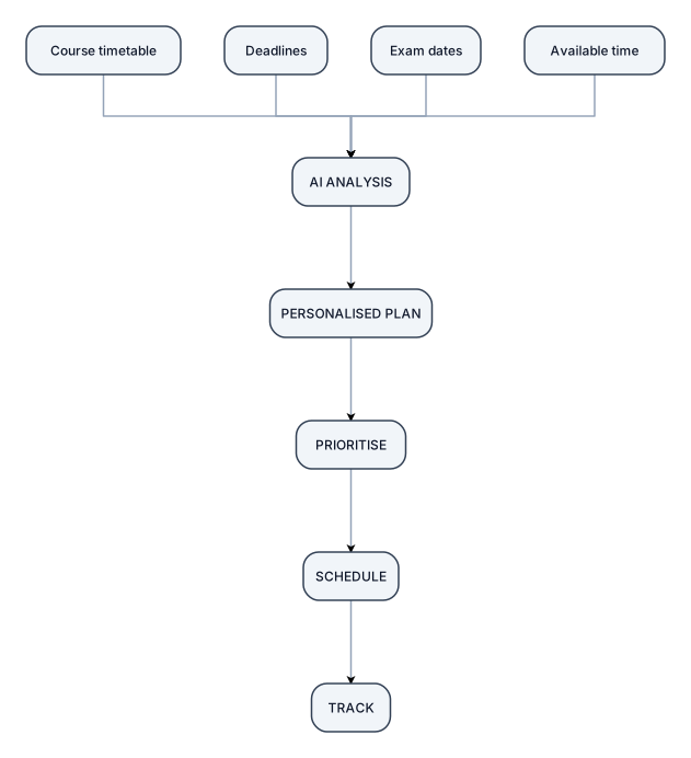
STUDENT INPUT Course timetable Deadlines Exam dates Available time ↓ AI ANALYSIS ↓ PERSONALISED PLAN ↓ PRIORITISE → SCHEDULE → TRACK
یه دیاگرام بساز از مرحله ثبت سفارش تا ارسال به تولید کننده و از اونجا ارسال برای مدیر پخش و بعدش پخش کنندگان و بعدش مشتری

Protein Precipitation & Extraction 300µL sample → Transfer to an Abgene 2.2 mL deep-well plate → 1200µL ACN + 1% FA + IS → Vortex 10min → Centrifuge 3,940g, 15min, 4°C. Conditioning EMR-PFAS Food II Plate Wash twice with 500µL of ACN/MeOH (1:1, v/v) + 1% FA → eluted under gravity Plate Pre-equilibration 150µL sample supernatant ( replace residual rinsing dead volume) → waste Dry EMR-PFAS plate Completely dryness with Ultra-high-purity N₂ at 20 psi (1min approx.) Loaded sample extract Place 96-well collection plate underneath EMR-PFAS plate → 1000 µL sample extract into each well → Allow to elute under gravity → Apply positive pressure to completely elute solvent Prevent analyte loss 30 µL of 1% ammonium hydroxide in acetonitrile to the collected eluate → Vortex for 5 min Evaporation Evaporate to complete dryness (ultra-high-purity N₂, 50 °C, 2h approx.) Reconstitution 50 µL water/methanol (20:80, v/v) Final mixing & clarification Vortex 5 min → Sonicate 5 min → Centrifuge 3,940 × g for 3 min
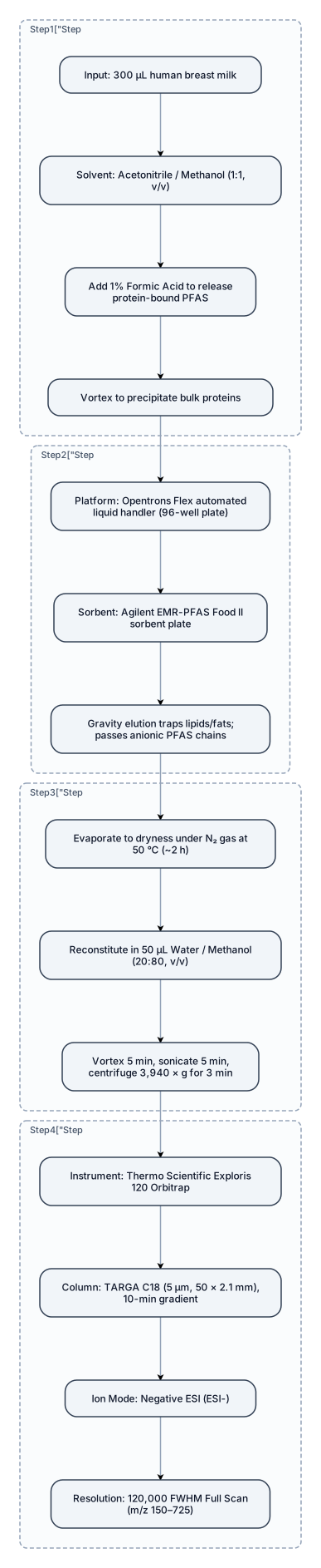
Step 1: Extraction & Protein DisruptionSample Input: 300 µL human breast milk.Solvent: Acetonitrile / Methanol (1:1, v/v).Critical Modifier: Add 1% Formic Acid to release protein-bound PFAS.Mixing: Thorough vortexing to precipitate bulk proteins.Step 2: Automated Matrix CleanupPlatform: Opentrons Flex automated liquid handler (96-well plate format).Sorbent Chemistry: Agilent EMR-PFAS Food II sorbent plate.Mechanism: Gravity elution traps lipids/fats while selectively passing anionic PFAS chains through the plate.Step 3: Concentration & ReconstitutionEvaporation: Blow down to absolute dryness under a gentle stream of \(N_{2}\) gas at 50 °C (~2 hours).Reconstitution: 50 µL of Water / Methanol (20:80, v/v).Final Clarification: 5 min vortex, 5 min sonication, and centrifugation at 3,940 × g for 3 min.Step 4: Orbitrap HRMS AnalysisInstrument: Thermo Scientific Exploris 120 Orbitrap.Column: TARGA C18 (5 µm, 50 × 2.1 mm) running a 10-minute total gradient block.Ion Mode: Negative Electrospray Ionization (ESI-).Resolution: 120,000 FWHM Full Scan (m/z 150–725) to eliminate heavy milk matrix backgrounds.
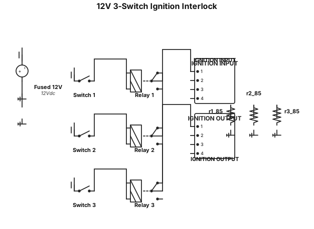
Create a simple 12V automotive 3-switch ignition interlock schematic. Use THREE Bosch-style 5-pin SPDT automotive relays. Clearly label EVERY relay terminal: 30, 85, 86, 87, and 87a. Each relay is controlled by one SPST toggle switch: * Terminal 85 of each relay goes to ground. * Terminal 86 receives fused 12V through its corresponding switch. The ONLY switch combination that should provide continuity from IGNITION INPUT to IGNITION OUTPUT is: Switch 1 = ON Switch 2 = OFF Switch 3 = ON Wire the ignition signal path exactly like this: IGNITION INPUT → Relay 1 terminal 30 Relay 1 terminal 87 → Relay 2 terminal 30 Relay 2 terminal 87a → Relay 3 terminal 30 Relay 3 terminal 87 → IGNITION OUTPUT Relay 1 must be energized for continuity. Relay 2 must be DE-ENERGIZED for continuity. Relay 3 must be energized for continuity. Do NOT add an ignition coil, ballast resistor, distributor, ECU, starter, battery charging system, or any other vehicle components. Do NOT invent additional connections. Show only: * Fused 12V control power * 3 toggle switches * 3 SPDT relays * Grounds * IGNITION INPUT * IGNITION OUTPUT Make the schematic suitable for physically wiring standard automotive relays and clearly show all terminal numbers.
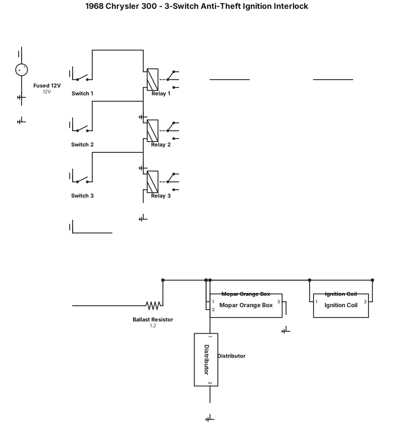
Create a 12V automotive wiring diagram for a 1968 Chrysler 300 with a 440 V8 and Mopar Orange Box electronic ignition. I want a 3-switch anti-theft ignition interlock using three 12V Bosch-style 5-pin SPDT relays (30, 85, 86, 87, 87a). The ignition should receive power ONLY with this combination: Switch 1 = ON Switch 2 = OFF Switch 3 = ON Each switch controls its relay coil: terminal 85 to ground and terminal 86 through its switch to fused 12V. Wire the ignition-enable path in series: Ignition source → Relay 1 terminal 30 → 87 → Relay 2 terminal 30 → 87a → Relay 3 terminal 30 → 87 → ignition system. Relay 1 uses 87 because Switch 1 must be ON. Relay 2 uses 87a because Switch 2 must be OFF. Relay 3 uses 87 because Switch 3 must be ON. Clearly label all relay terminals, switches, fused 12V, grounds, ignition input, and ignition output. Show the Mopar Orange Box, ballast resistor, ignition coil, and distributor for context. This circuit disables ignition/spark, not starter-motor power. Only ON-OFF-ON should allow the engine to have ignition.
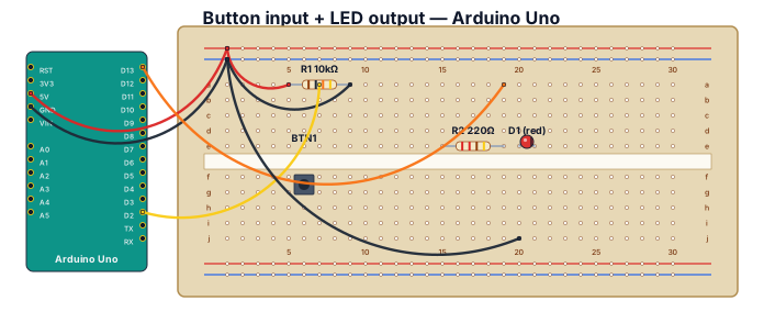
A breadboard wiring diagram for an Arduino Uno reading a button press and lighting an LED: button with pull-down resistor on D2, LED with 220-ohm resistor on D13
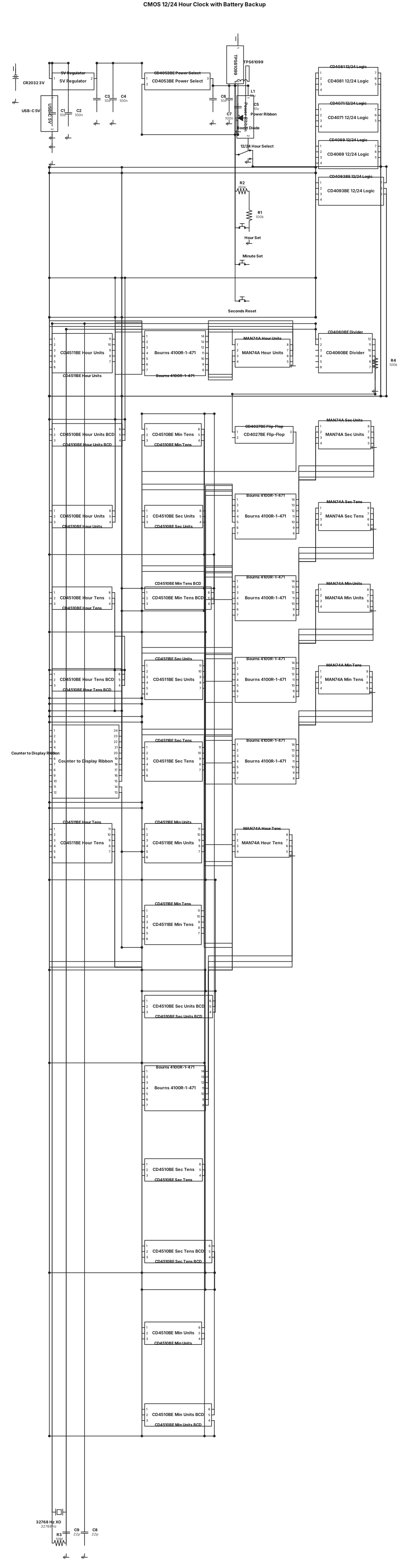
Using through-hole components where possible , create the following circuit, 12/24 hour clock using CMOS chips namely the cd4510be and the cd4511. Timebase will be a 32768 kHz Crystal Oscillator (XO), cd4060be and a cd4027be to get the 1Hz. Displays for the time will be MAN74A seven segment displays using 14 pin dip sockets current limit will be via six Bourns 4100R-1-471 isolated 470Ω resistor networks in a 14 pin dip package. The clock display will be HH:MM:SS Counter board should contain the timebase, 6 x cd4510 and any addition logic chips, display board should contain the MAN74A displays, 6x cd4511be and the six Bourns 4100R-1-471 isolated 470Ω resistor networks in a 14 pin dip package. Boards should be connected via ribbon connectors The power for the circuit will come from a USBC connector, for battery backup use the TPS61099, design for a 3 V CR2032 coin cell that powers only the oscillator/counters while automatically blanking the displays. Normal operation would use a regulated 5 V input. For time setting add hour-set, minute-set, seconds-reset pushbuttons, plus a 12/24-hour selector switch?. Do not use the ADA4927, need to keep the design all CMOS where ever possible try using the cd4053be instead and chips like the cd4093be, cd4081, cd4071, cd4069 for 12/24 hour logic.
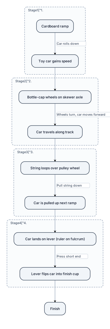
Create a simple diagram of a homemade machine that moves a small toy car. Use 4 simple machines: an inclined plane (ramp), wheel and axle, pulley, and lever. Make it easy to build at home using cardboard, string, bottle caps, LEGO or paper. Label each simple machine and show arrows explaining how the machine moves the car.

Create a horizontal left-to-right workflow for an on-site diagnostic mobile medical van. There is no AI involved. Show the complete patient journey from arrival to leaving with the report. The workflow should include four roles: Patient, Registration Staff, Nurse, Doctor, and Lab Technician. Start with Patient Arrival → Registration → Waiting Queue → Nurse Vitals Check → Symptoms & Basic History → Doctor Clinical Assessment → Doctor Decides Test Is Required → Select On-Site Test → Nurse Prepares Patient → Nurse Collects Sample → Lab Technician Checks Sample → Lab Technician Performs Test → Result Generated On-Site → Lab Technician Verifies Result → Result Recorded → Doctor Reviews Result → Clinical Diagnosis/Finding → Treatment/Advice/Referral → Report Generation → Doctor/Nurse Verifies Report → Patient Receives Report → Patient Leaves. Use clear boxes and arrows, with different visual styles for major stages, decisions, staff actions, and patient actions. Keep the workflow simple, professional, and easy to understand.
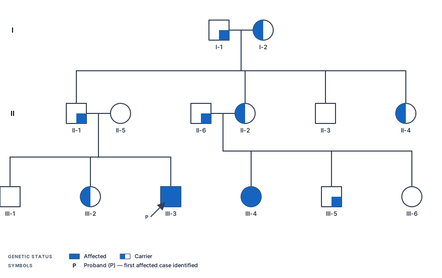
Create a three-generation pedigree demonstrating autosomal recessive inheritance of Spinal Muscular Atrophy Type II (SMA2) caused by mutations in the SMN1 gene. Use standard pedigree symbols: squares for males, circles for females, filled symbols for affected individuals, half-filled symbols for unaffected carriers, and unfilled symbols for unaffected non-carriers. Label each individual by generation and number (I-1, I-2, II-1, etc.) and include the genotype below each individual. Use A for a normal SMN1 allele and a for a disease-causing allele, so affected individuals are aa, carriers are Aa, and unaffected non-carriers are AA. Include at least three offspring in Generation II and at least three offspring in Generation III. Have two unaffected carrier parents (Aa × Aa) in Generation II produce an affected child (aa) in Generation III. Include both males and females in the pedigree. Identify one affected individual in Generation III as the proband using an arrow. Make all individuals living so no deceased symbols are necessary. Title the pedigree “Autosomal Recessive Inheritance of Spinal Muscular Atrophy Type II (SMA2).” Include a legend explaining the symbols and genotypes.
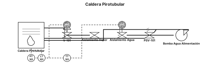
caldera pirotubular

i want a mule 4 flow chart I want something like this sap-papi will send IDOC to awi-sap-cust-to-aero-papi awi-sap-cust-to-aero-papi will send IDOC to awi-sap-
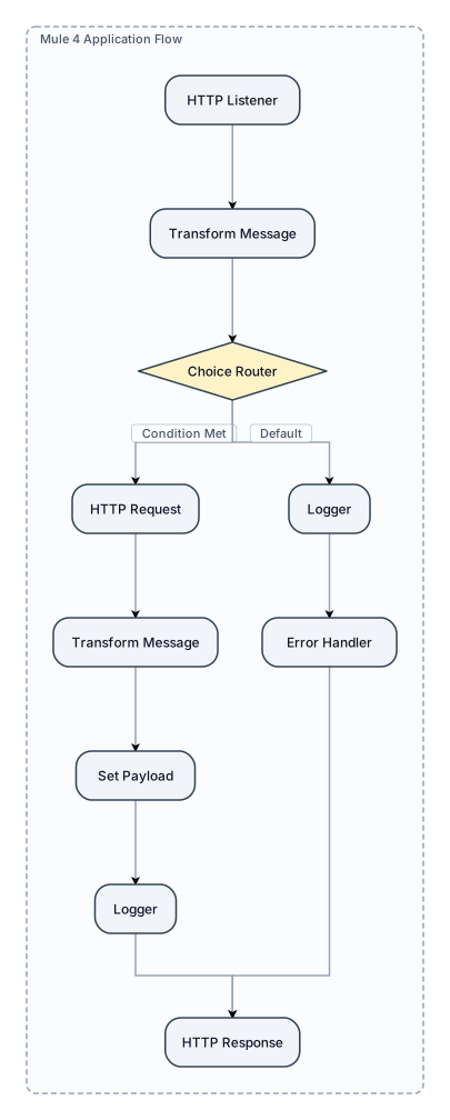
i want a mule 4 flow chart I want something like this
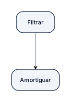
Necesito un diagrama de la palabra filtrar o amortiguar

Create a simple, clean one-page landscape flowchart titled: “Learning Environment Registration & Assessment Journey” Show these 7 stages as large boxes connected by arrows: 1. REGISTER Register the learning environment with NSS ↓ 2. CONFIRM SCOPE Confirm assessment requirements ↓ 3. PREPARE Prepare the environment and required evidence ↓ 4. ASSESS Independent assessment ↓ 5. ACTION Address findings or provide further evidence ↓ 6. RECOGNISE NSS assessment outcome awarded ↓ 7. MAINTAIN Ongoing compliance and reassessment After ASSESS, show a simple decision: Meets requirements? YES → RECOGNISE NO → ACTION → REASSESS Use a professional certification-scheme style with large boxes, clear arrows, minimal text, simple icons and generous white space. Avoid complex branching or detailed explanations.
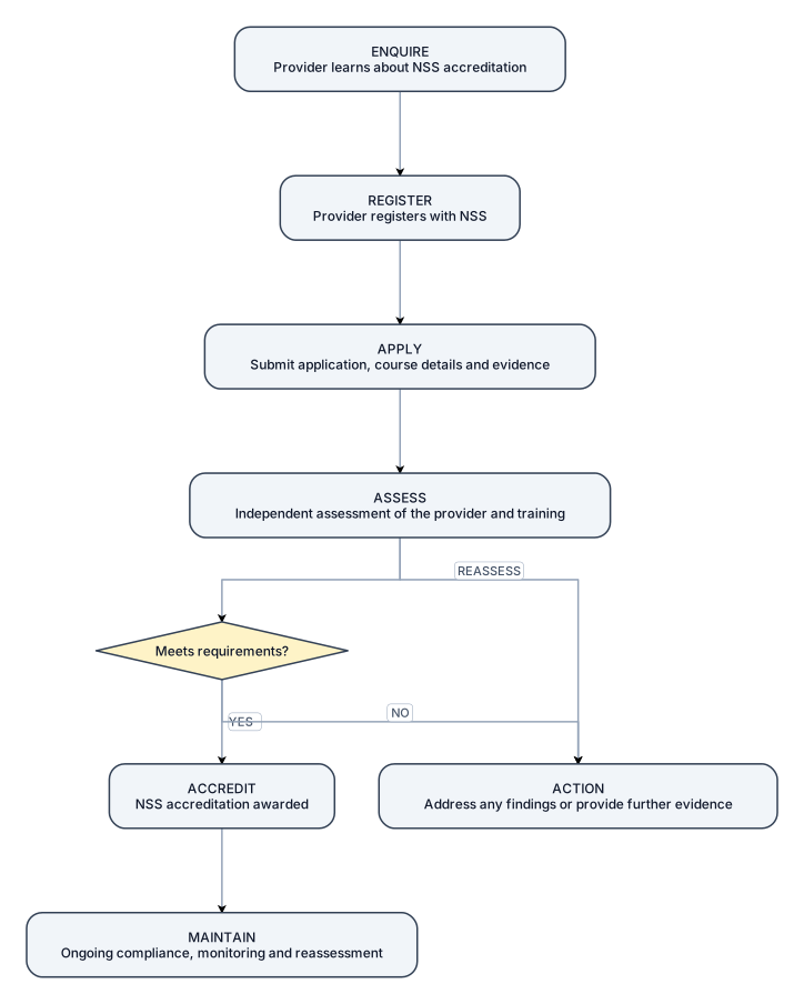
Create a simple, clean one-page landscape flowchart titled: “Education & Training Provider Accreditation Journey” Show these 7 stages as large boxes connected by arrows: 1. ENQUIRE Provider learns about NSS accreditation ↓ 2. REGISTER Provider registers with NSS ↓ 3. APPLY Submit application, course details and evidence ↓ 4. ASSESS Independent assessment of the provider and training ↓ 5. ACTION Address any findings or provide further evidence ↓ 6. ACCREDIT NSS accreditation awarded ↓ 7. MAINTAIN Ongoing compliance, monitoring and reassessment After ASSESS, show a simple decision: Meets requirements? YES → ACCREDIT NO → ACTION → REASSESS Use a professional certification-scheme style with large boxes, clear arrows, minimal text, simple icons and generous white space. Avoid complex branching or detailed explanations.