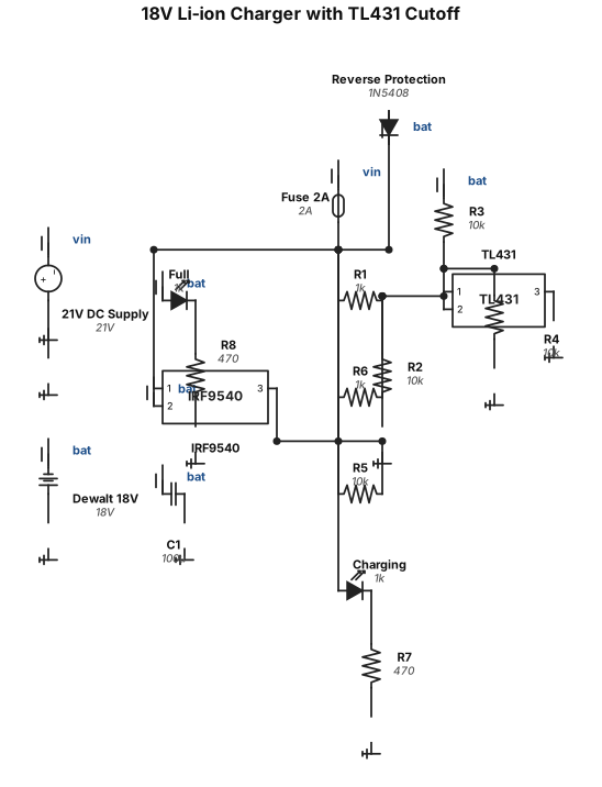
Hey I have Dewalt 18v 2.0 AH li-on battery now I am charging this battery with 21v 2A dc power supply now I need two indicators one for battery charging and other one for when battery full charged led need to glow and also need cut off circuit after full charge circuit need turn off automatically using Tl431
NODE ARCHIVE · REAL DIAGRAM BRIEFS
Diagram Examples from Real Visitor Prompts
Browse eligible diagrams shared by FreeDiagram visitors, inspect the exact prompts, and build your own version.
Browse 3265 real creationsCOMMUNITY OUTPUTS · EXACT PROMPTS
Circuit Diagrams
Showing 265–270 of 270. No stock examples or system defaults. Choose a tool, study a real result, then reopen its prompt as your starting point.

Create a complete, buildable schematic for a MONO 2-band Baxandall audio tone control preamplifier. POWER: - Single +12V DC supply - GND = 0V - Create VREF = +6V using two 10kΩ resistors as a voltage divider. - Add 100µF and 100nF capacitors from VREF to GND. - Use NE5532 dual op-amp. - Show the correct NE5532 pin numbers and power pins. - NE5532 pin 8 = +12V - NE5532 pin 4 = GND AUDIO INPUT: - Mono audio input - Input coupling capacitor = 1µF - Input bias/reference must be connected correctly to VREF. - Add an input volume control using a 50kΩ potentiometer. TONE CONTROL: - Use a proper ACTIVE Baxandall 2-band tone control. - Bass control = 50kΩ potentiometer. - Treble control = 50kΩ potentiometer. - Bass center frequency approximately 100Hz. - Treble center frequency approximately 10kHz. - Tone controls must be centered around VREF for single-supply operation. - Clearly show every resistor and capacitor value. - Clearly show every connection between the tone-control components and the NE5532. OUTPUT: - Mono audio output. - Output must be biased correctly around VREF. - Add an output coupling capacitor so the external amplifier receives no DC. - Output should be suitable for a TPA3116D2 Class-D amplifier input. IMPORTANT: - Use standard electronic schematic symbols. - Show ALL component values. - Show ALL NE5532 pin numbers. - Show +12V, GND and VREF clearly. - Do not omit any component. - Do not use a generic block diagram. - Generate a real electronic schematic with wires and component symbols. - Make it clean, large and easy to read. - The final result must be suitable for manually rebuilding on a PCB.
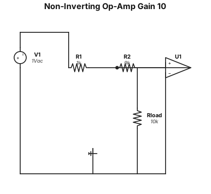
A non-inverting op-amp amplifier circuit with a gain of 10, using a 1 kΩ input resistor and a 9 kΩ feedback resistor
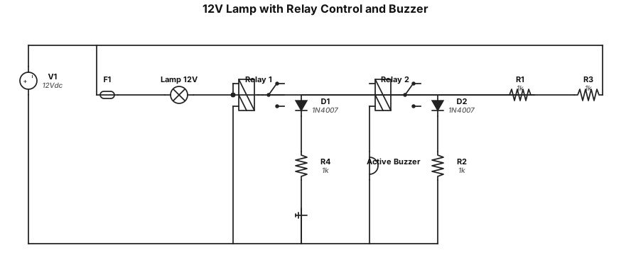
Нарисуй простую электрическую схему: лампа 12 В стоит в силовой цепи вместо предохранителя. Лампа коммутируется нормально разомкнутым контактом реле 1. Катушка реле 1 включена параллельно силовой линии. Второе реле (реле 2) с перекидными контактами управляет активным зуммером: зуммер включён через нормально замкнутый контакт реле 2. Катушка реле 2 питается через NO‑контакт реле 1 (то есть при срабатывании реле 1 реле 2 тоже срабатывает и отключает зуммер). Добавь два защитных диода параллельно катушкам обоих реле. Используй стандартные символы компонентов и подпиши их.»
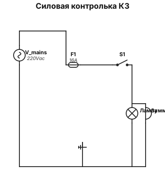
Нужна силовая контролька КЗ есть — лампа горит, зуммер молчит; КЗ нет — лампа не горит (или горит слабо), зуммер пищит.
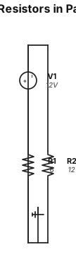
Mạch điện gồm 2 điện trở R₁ = 6 Ω, R₂ = 12 Ω mắc song song vào nguồn điện có hiệu điện thế U = 12 V. Tính điện trở tương đương của mạch, cường độ dòng điện qua mạch chính và qua từng điện trở.