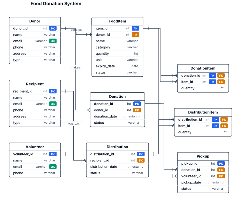
An entity-relationship diagram for the topic is food donation system relationship between entity
NODE ARCHIVE · REAL DIAGRAM BRIEFS
Diagram Examples from Real Visitor Prompts
Browse eligible diagrams shared by FreeDiagram visitors, inspect the exact prompts, and build your own version.
Browse 3336 real creationsCOMMUNITY OUTPUTS · EXACT PROMPTS
All visitor creations
Showing 3001–3024 of 3336. No stock examples or system defaults. Choose a tool, study a real result, then reopen its prompt as your starting point.
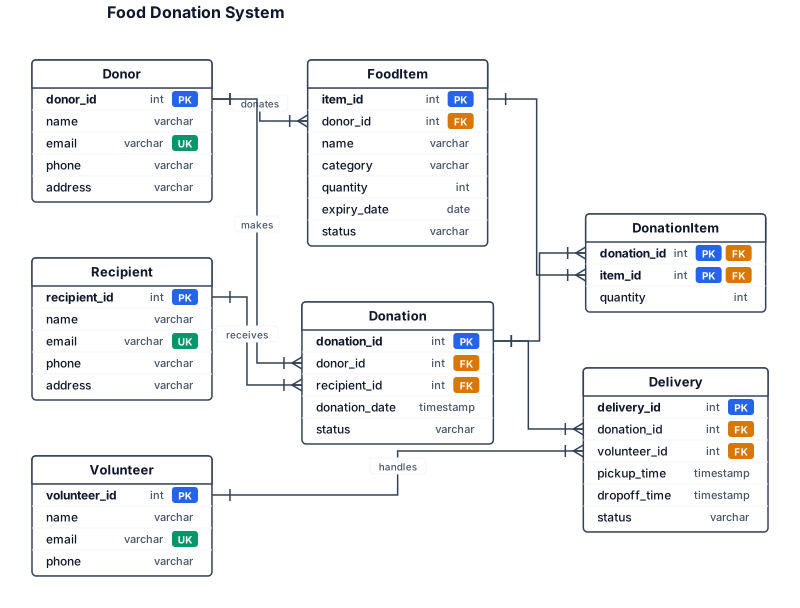
An entity-relationship diagram for the topic is food donation system relationship between entitys
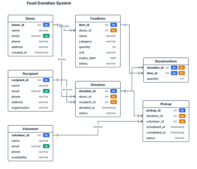
An entity-relationship diagram for the topic is food donation system
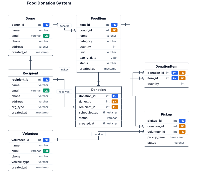
An entity-relationship diagram for a SaaS app the topic is food donation system
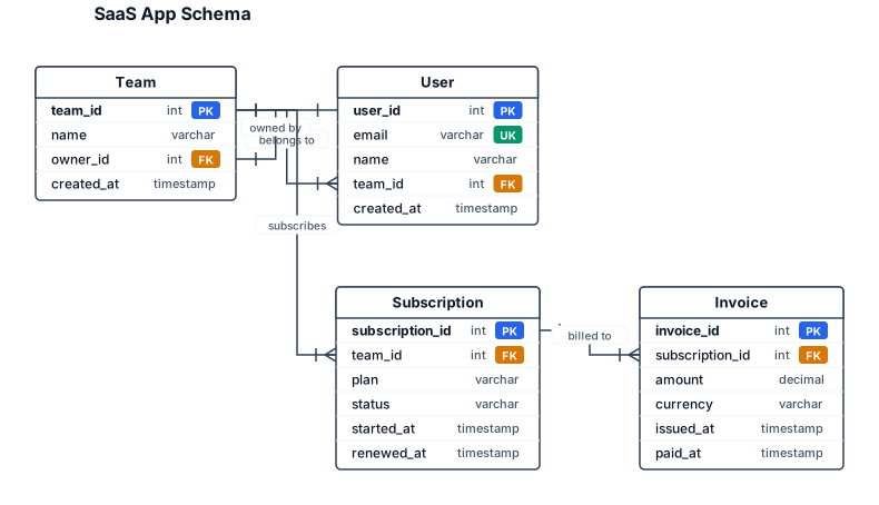
An entity-relationship diagram for a SaaS app with users, teams, subscriptions, and invoices
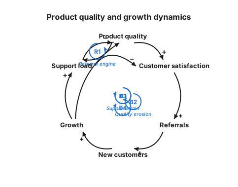
A causal loop diagram showing how product quality, customer satisfaction, referrals, growth, and support load reinforce or balance each other

The system is equipped with 2 sets of vertical U‑tube semi‑volume water‑to‑water heat exchangers. The heat exchanger shell diameter is DN1200, volume 1.4 m³, design pressure of tube‑side and shell‑side is 1.0 MPa, heat transfer area is 16.5 ㎡. Shell, tube‑side and heat exchange tubes are made of 304 stainless steel; supports are 304 stainless steel plus carbon steel. Auxiliary equipment includes circulating water pumps and pressure tanks. Instruments and accessories: pressure gauges, thermometers, transmitters, safety valves, blow‑down valves. The system includes primary‑side pipelines & valves, secondary‑side pipelines & valves. Control objectives: Complete heat exchange between primary and secondary side to meet cooling and heating requirements of the system. Monitor pressure and temperature of heat exchanger medium. Safety overpressure relief via safety valves. Blow‑down function through blow‑down valves. Circulating pumps provide medium circulation. All equipment, instruments and valves shall be configured in accordance with construction drawings and relevant design codes and specifications

Create a clean academic 0-Level DFD for: “ClickMe – AI Event Photo Retrieval System” LAYOUT: Use a wide landscape layout with plenty of empty space. Do NOT make the diagram compact or crowded. Place the elements like this: LEFT: Rectangle: PHOTOGRAPHER CENTER: One large process box: (ClickMe – AI Event Photo Retrieval System) RIGHT: Rectangle: GUEST ARROWS: PHOTOGRAPHER → CLICKME Label: Event Photos + Event ID GUEST → CLICKME Label: Selfie + Event ID CLICKME → GUEST Label: Matching Photographs IMPORTANT: - Exactly 2 external entities: Photographer and Guest - Exactly 1 central process: ClickMe - No other boxes - No internal processes - No ChromaDB - No Face Detection - No Face Embedding - No Similarity Search - No extra text - No icons - No decoration - Do not stack the elements vertically - Do not overlap arrows or labels - Keep large spacing between all elements - Use clear directional arrows - Use black text and black lines on white background - Professional college-project style - Landscape orientation - High resolution The final diagram should be visually simple: PHOTOGRAPHER → CLICKME → GUEST ↑ │ GUEST → CLICKME Caption: Figure 5.3.1: 0-Level DFD of ClickMe

Create a clean and professional academic 0-Level Data Flow Diagram (DFD) for a college project titled: “ClickMe – AI Event Photo Retrieval System” Use standard DFD notation. IMPORTANT: This is a 0-Level DFD, so show the complete ClickMe application as ONE single central process. Do NOT show internal processes such as face detection, face embedding generation, similarity search, ChromaDB, OpenCV, InsightFace, Docker, or any other internal component. Include exactly TWO external entities: 1. PHOTOGRAPHER 2. GUEST Include exactly ONE central process: “ClickMe – AI Event Photo Retrieval System” Data flows: 1. PHOTOGRAPHER → ClickMe System Label the arrow: “Event Photos + Event ID” 2. GUEST → ClickMe System Label the arrow: “Selfie + Event ID” 3. ClickMe System → GUEST Label the arrow: “Matching Photographs” The diagram should clearly show that the photographer provides event photographs and Event ID to the system, while the guest provides a selfie and Event ID to search for photographs. The system returns matching photographs to the guest. Use: - Standard DFD symbols - External entities as rectangles - The complete ClickMe system as one process - Clearly labelled directional arrows - Black and white academic style - White background - Clean rectangular shapes - Simple professional typography - Landscape orientation - No decorative graphics - No icons - No photographs - No unnecessary text - No extra entities - No extra processes Make the diagram suitable for direct insertion into a college project report. Title/caption should be: “Figure 5.3.1: 0-Level DFD of ClickMe”
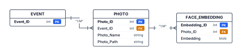
Create a clean academic ER diagram for my AI Event Photo Retrieval System called ClickMe. The system stores event photographs and facial embeddings for selfie-based photo retrieval. Use three main database entities: EVENT, PHOTO, and FACE_EMBEDDING. EVENT contains PK Event_ID. PHOTO contains PK Photo_ID, FK Event_ID, Photo_Name, and Photo_Path. FACE_EMBEDDING contains PK Embedding_ID, FK Photo_ID, and facial Embedding. Show a one-to-many relationship between EVENT and PHOTO because one event contains many photographs. Show a one-to-many relationship between PHOTO and FACE_EMBEDDING because one photograph may contain multiple detected faces and therefore multiple facial embeddings. Show a separate Guest Selfie input outside the database entities. The Guest Selfie is processed to generate a facial embedding and is used for similarity search against the stored facial embeddings in ChromaDB; it is not a permanent database entity. Mention ChromaDB as the vector database used to store and search facial embeddings, but do not represent ChromaDB as an entity. Use standard ERD notation, clear rectangles, PK/FK labels, cardinality 1:M, black-and-white academic style, white background, landscape layout, no unnecessary decoration, suitable for a college project report.
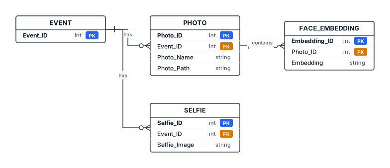
Create a clean academic Entity Relationship Diagram (ERD) for an AI Event Photo Retrieval System called ClickMe. Include four entities: EVENT, PHOTO, FACE_EMBEDDING, and SELFIE. EVENT has Event_ID as the primary key. PHOTO has Photo_ID as the primary key, Event_ID as a foreign key, and Photo_Name/Photo_Path. FACE_EMBEDDING has Embedding_ID as the primary key, Photo_ID as a foreign key, and Embedding. SELFIE has Selfie_ID as the primary key, Event_ID as a foreign key, and Selfie_Image. Show these relationships: one EVENT can have many PHOTOS; one PHOTO can contain multiple FACE_EMBEDDINGS; one EVENT can have multiple SELFIES. Use standard ERD notation, clear rectangles, primary key and foreign key labels, simple black-and-white academic style, no unnecessary decoration, white background, landscape layout, suitable for a college project report.
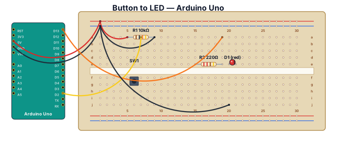
A breadboard wiring diagram for an Arduino UnoQ reading a button press and lighting an LED: button with pull-down resistor on D2, LED with 220-ohm resistor on D13
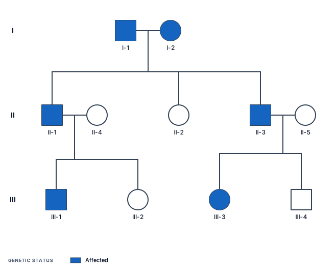
A three‑generation pedigree chart showing autosomal dominant inheritance of widow’s peak, with two affected grandparents, one affected child, one unaffected child, and cousins showing a full range of dominant, heterozygous, and unaffected phenotypes.
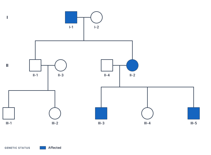
A three‑generation pedigree chart showing autosomal dominant inheritance of widow’s peak, with an affected grandfather, an unaffected grandmother, one unaffected child, one affected child, and grandchildren showing complete absence of the trait in one branch and mixed expression in the other.
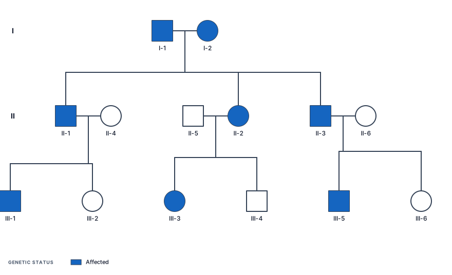
A three‑generation pedigree chart showing autosomal dominant inheritance of widow’s peak, with two affected grandparents, three affected children, and six grandchildren showing both affected and unaffected phenotypes depending on parental genotype
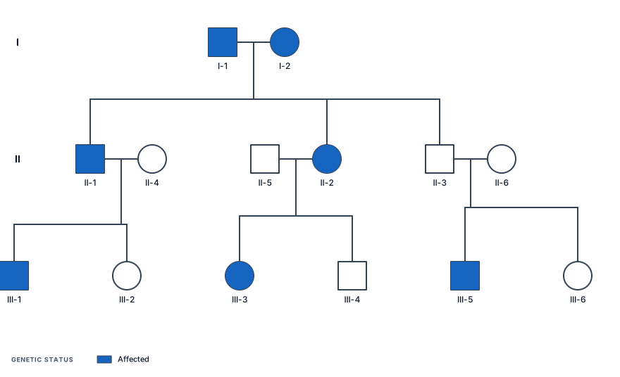
A three‑generation pedigree chart showing autosomal dominant inheritance of widow’s peak, with two affected grandparents, three children with mixed genotypes (one homozygous dominant, one heterozygous, one unaffected), and six grandchildren showing a 1:1 ratio of affected to unaffected individuals across branches. Titled Family C
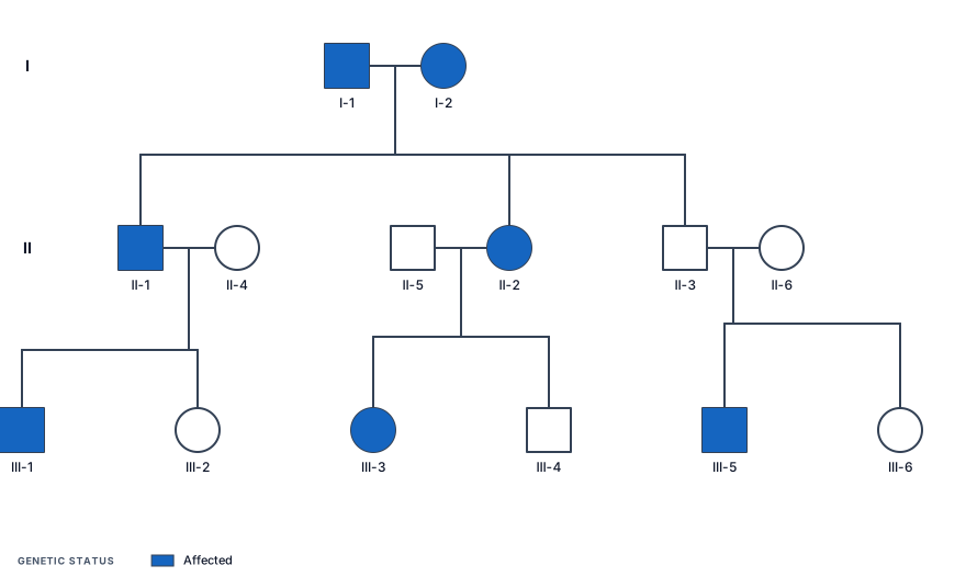
A three‑generation pedigree chart showing autosomal dominant inheritance of widow’s peak, with two affected grandparents, three children with mixed genotypes (one homozygous dominant, one heterozygous, one unaffected), and six grandchildren showing a 1:1 ratio of affected to unaffected individuals across branches
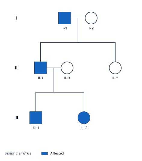
A three‑generation pedigree chart showing autosomal dominant inheritance of widow’s peak, with an affected grandfather, an unaffected grandmother, one affected child, one unaffected child, and two affected grandchildren
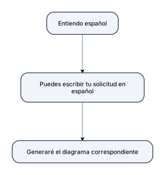
Me entiendes si escribo mi solicitud en español?
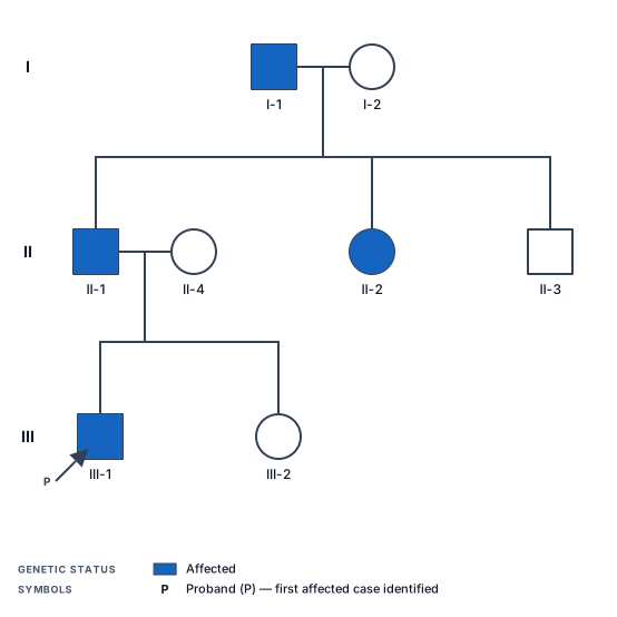
A three-generation pedigree chart showing autosomal dominant inheritance of Huntington disease, with the grandfather affected, two carrier children, and one affected grandchild

5. "What do you know about the proposal process?" You don't need to pretend you're a Shipley expert. Show that you understand the lifecycle. Answer At a high level, I understand the proposal process as starting with understanding the solicitation and identifying every requirement that needs a response. From there, the team builds a compliance matrix, assigns responsibilities, establishes a schedule and coordinates the technical, management and pricing inputs. As the proposal develops, the team goes through reviews and revisions to make sure the response is compliant, accurate and consistent. On the pricing side, you need to develop the underlying cost elements and BOEs, validate the assumptions, build the pricing model and make sure the pricing artifacts align with the technical and contractual requirements. The final stage is really about compliance, quality control and making sure everything is submitted correctly and on time. I haven't owned every part of that lifecycle myself, but I've spent years supporting the pricing portion and working with the teams responsible for it, so I'm very familiar with the environment.

Create a complete, buildable schematic for a MONO 2-band Baxandall audio tone control preamplifier. POWER: - Single +12V DC supply - GND = 0V - Create VREF = +6V using two 10kΩ resistors as a voltage divider. - Add 100µF and 100nF capacitors from VREF to GND. - Use NE5532 dual op-amp. - Show the correct NE5532 pin numbers and power pins. - NE5532 pin 8 = +12V - NE5532 pin 4 = GND AUDIO INPUT: - Mono audio input - Input coupling capacitor = 1µF - Input bias/reference must be connected correctly to VREF. - Add an input volume control using a 50kΩ potentiometer. TONE CONTROL: - Use a proper ACTIVE Baxandall 2-band tone control. - Bass control = 50kΩ potentiometer. - Treble control = 50kΩ potentiometer. - Bass center frequency approximately 100Hz. - Treble center frequency approximately 10kHz. - Tone controls must be centered around VREF for single-supply operation. - Clearly show every resistor and capacitor value. - Clearly show every connection between the tone-control components and the NE5532. OUTPUT: - Mono audio output. - Output must be biased correctly around VREF. - Add an output coupling capacitor so the external amplifier receives no DC. - Output should be suitable for a TPA3116D2 Class-D amplifier input. IMPORTANT: - Use standard electronic schematic symbols. - Show ALL component values. - Show ALL NE5532 pin numbers. - Show +12V, GND and VREF clearly. - Do not omit any component. - Do not use a generic block diagram. - Generate a real electronic schematic with wires and component symbols. - Make it clean, large and easy to read. - The final result must be suitable for manually rebuilding on a PCB.
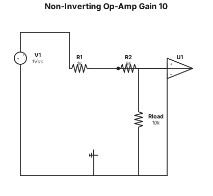
A non-inverting op-amp amplifier circuit with a gain of 10, using a 1 kΩ input resistor and a 9 kΩ feedback resistor
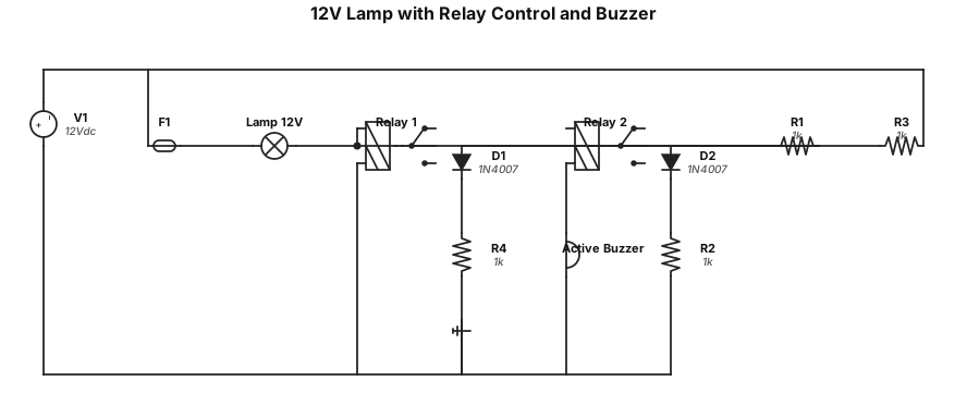
Нарисуй простую электрическую схему: лампа 12 В стоит в силовой цепи вместо предохранителя. Лампа коммутируется нормально разомкнутым контактом реле 1. Катушка реле 1 включена параллельно силовой линии. Второе реле (реле 2) с перекидными контактами управляет активным зуммером: зуммер включён через нормально замкнутый контакт реле 2. Катушка реле 2 питается через NO‑контакт реле 1 (то есть при срабатывании реле 1 реле 2 тоже срабатывает и отключает зуммер). Добавь два защитных диода параллельно катушкам обоих реле. Используй стандартные символы компонентов и подпиши их.»