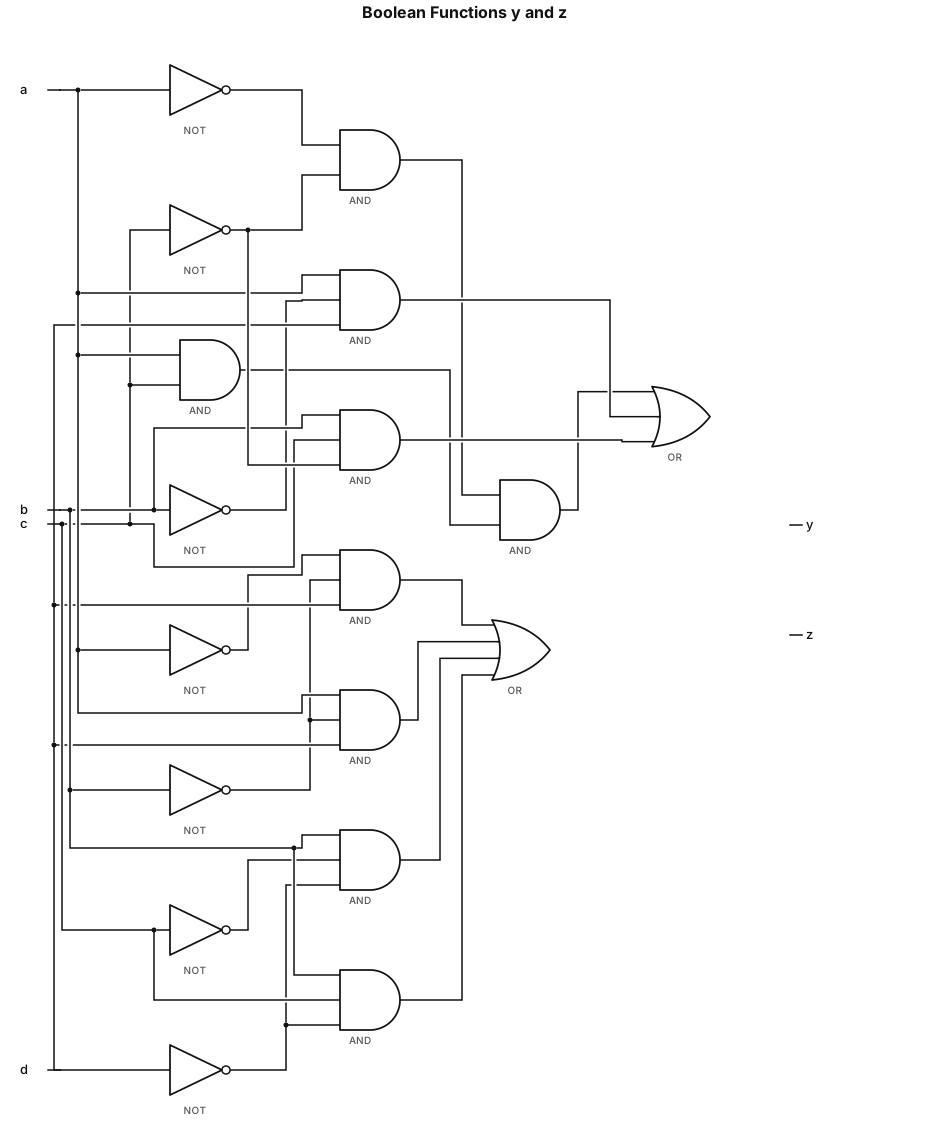
y = a'c' + ac + ab'd + bcd'; z = a'b'd + ab'd + bc'd' + bcd'
NODE ARCHIVE · REAL DIAGRAM BRIEFS
Diagram Examples from Real Visitor Prompts
Browse eligible diagrams shared by FreeDiagram visitors, inspect the exact prompts, and build your own version.
Browse 3257 real creationsCOMMUNITY OUTPUTS · EXACT PROMPTS
Boolean Expression To Logic Circuit
Showing 25–48 of 98. No stock examples or system defaults. Choose a tool, study a real result, then reopen its prompt as your starting point.
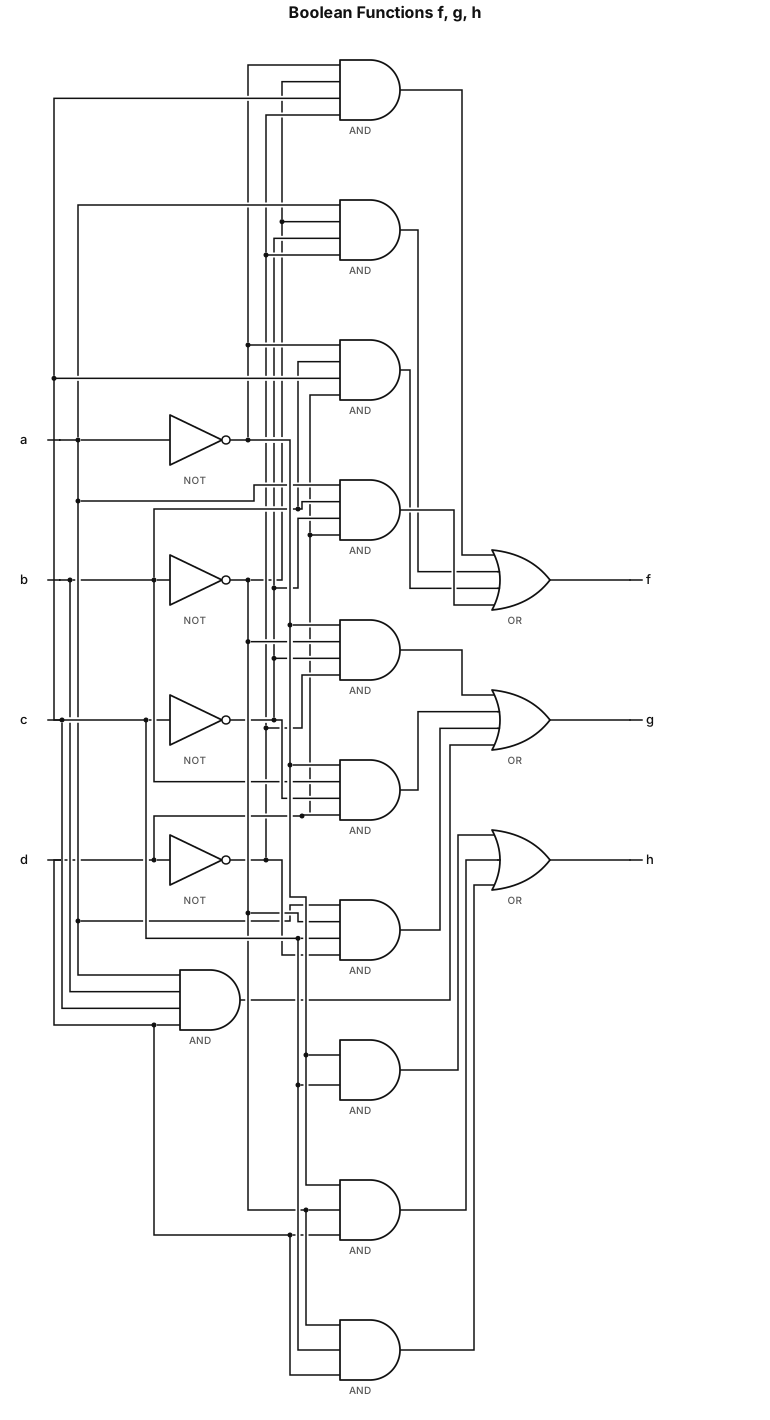
f = a'b'cd' + ab'c'd' + a'bcd + abc'd; a'b'c'd' + a'bc'd + ab'cd' + abcd; h = a'c + a'b'd + b'cd
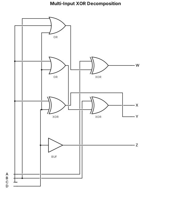
W=A⊕(B+C+D);X=B⊕(C+D);Y=C⊕D;Z=D plot using two input gates
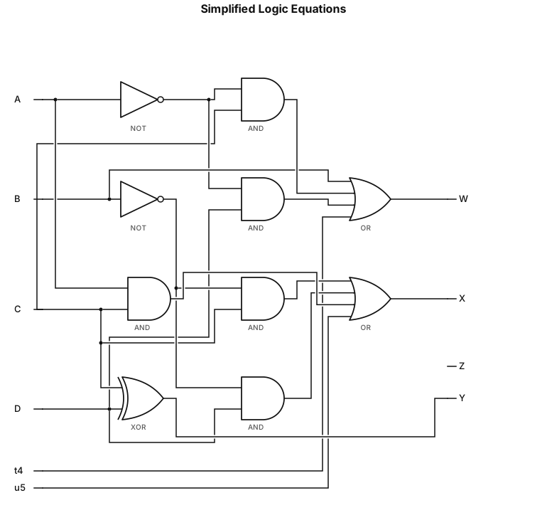
Final Simplified Equations Summary • \(\mathbf{W=B+A}^{\prime }\mathbf{C+A}^{\prime }\mathbf{D+AD}^{\prime }\) • \(\mathbf{X=B}^{\prime }\mathbf{C+B}^{\prime }\mathbf{D+AC+BC}^{\prime }\mathbf{D}^{\prime }\) • \(\mathbf{Y=C\oplus D}\) • \(\mathbf{Z=D}\)
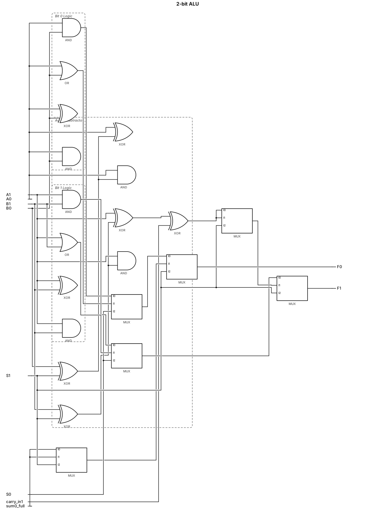
2.5 Design and Implementation of a 2-bit ALU Inputs: A = A1A0 and B = B1B0 S1 S0 Operation 0 0 A AND B 0 1 A OR B 1 0 A + B 1 1 A − B Design The ALU is designed to select one of four operations using 2×1 multiplexers and basic logic gates. The arithmetic operations use the required adder/subtractor logic.
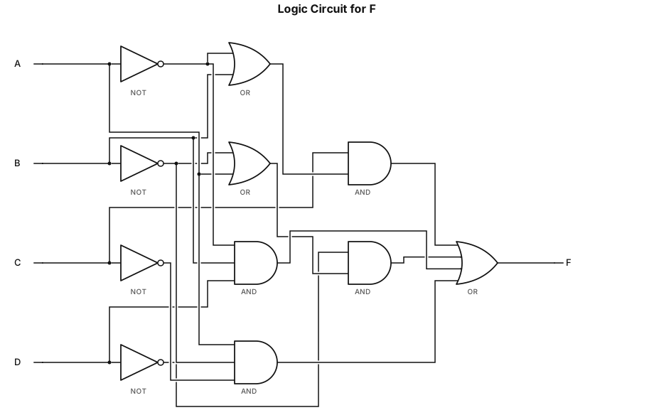
Draw the logic circuit diagram for F = C(A'+B)+D'(B'+A)+A'BD+AB'C'
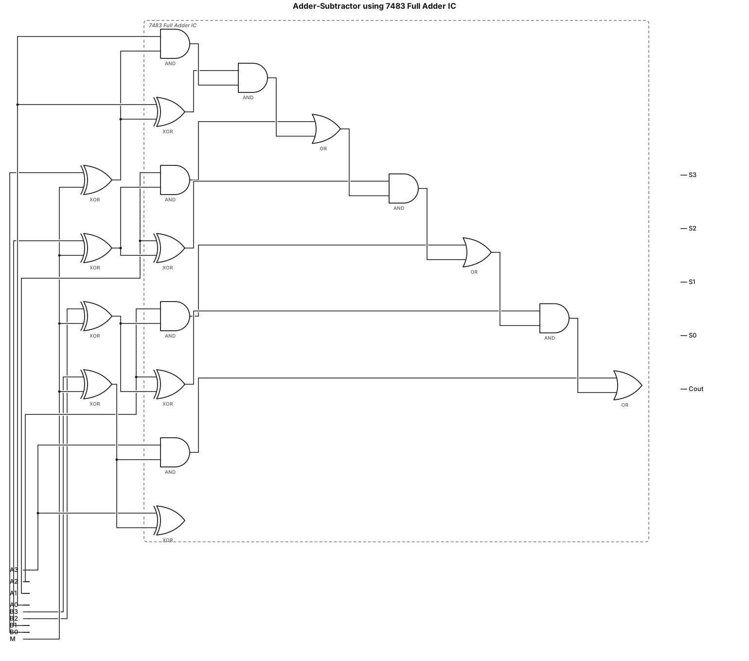
Implement Adder-Subtractor using 7483 Full adder IC
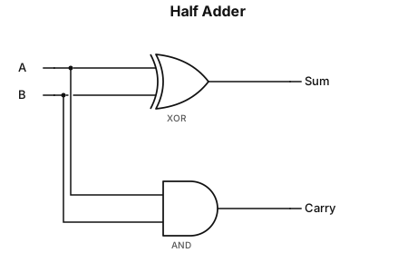
Half adder: Sum = A XOR B, Carry = AB
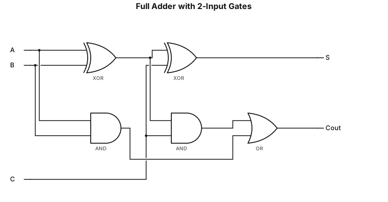
Cout=(A⊕B)C+AB using 2 input gates and S=A⊕B⊕C in one image
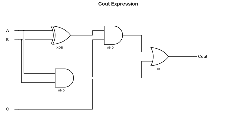
Cout=(A⊕B)C+AB using 2 input gates
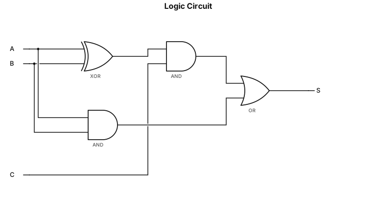
S=(A⊕B)C+AB using 2 input gates
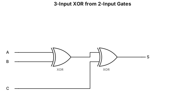
S=A⊕B⊕C using 2 input gates
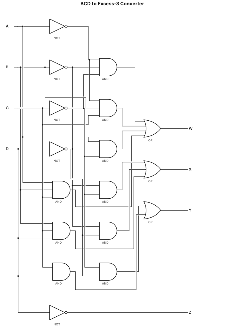
bcd to excess 3 ,inputs ABCD outputs WXYZ
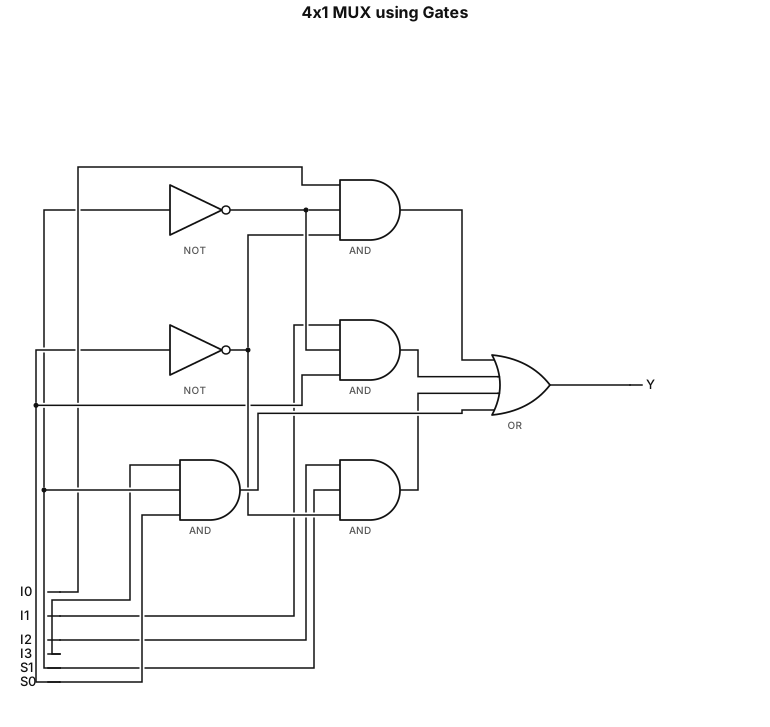
Implement 4x1 MUX using gates,S1,S0 are select lines ,I0,I1,I2,I3 are inputs,Y is output
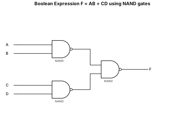
3) Implement a given Boolean expression using only NAND gates:F=AB+CD
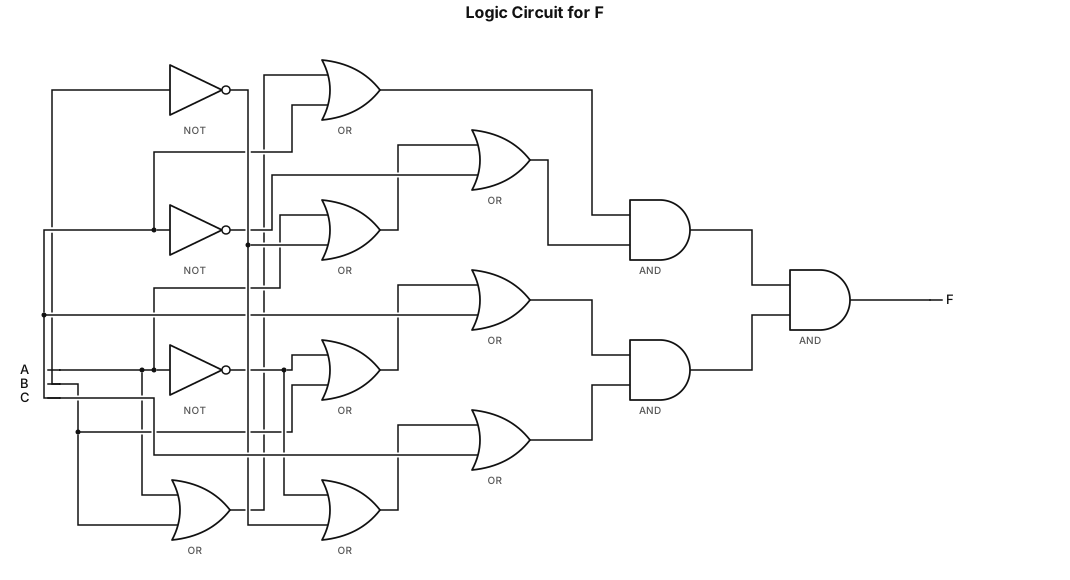
Draw the logic circuit diagram for (F=(A+B+C)(A+B'+C')(A'+B+C)(A'+B'+C) ), Strictly using less than or equal to 2 input gates Inputs A,B,C;output F.
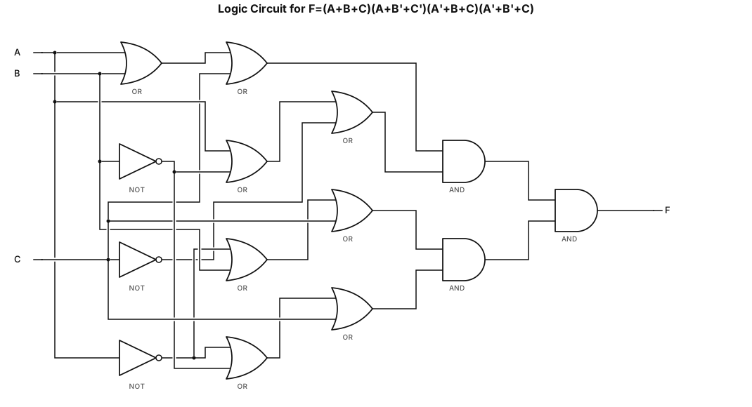
Draw the logic circuit diagram for (F=(A+B+C)(A+B'+C')(A'+B+C)(A'+B'+C) ), Strictly using less than or equal to 2 input gatesInputs A,B,C,D; output F.
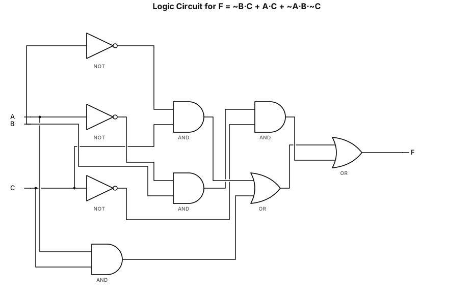
Draw the logic circuit diagram for (F=¯B C+AC+¯A B¯C), Strictly using less than or equal to 2 input gatesInputs A,B,C,D; output F.
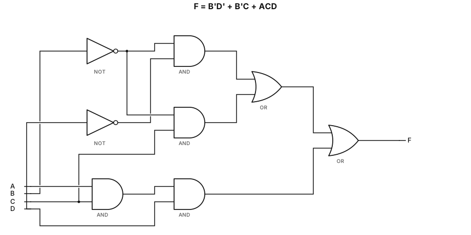
Draw the logic circuit diagram for F = B̅ D̅ + B̅ C + ACD, Strictly using less than or equal to 2 input gatesInputs A,B,C,D; output F.
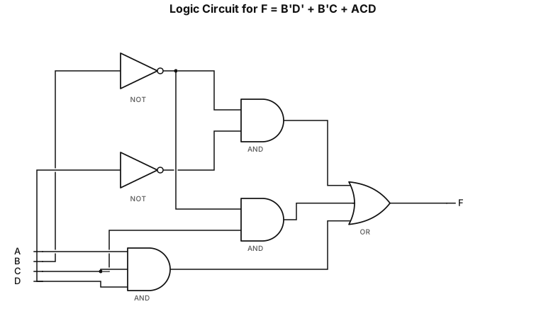
Draw the logic circuit diagram for F = B̅ D̅ + B̅ C + ACD, Inputs A,B,C,D; output F.
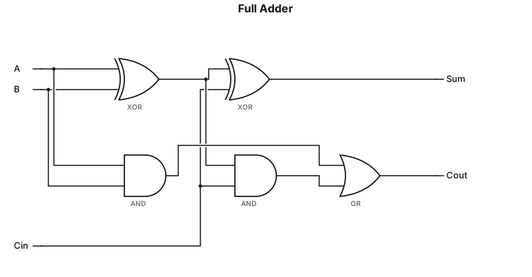
Implementation of Full Adder
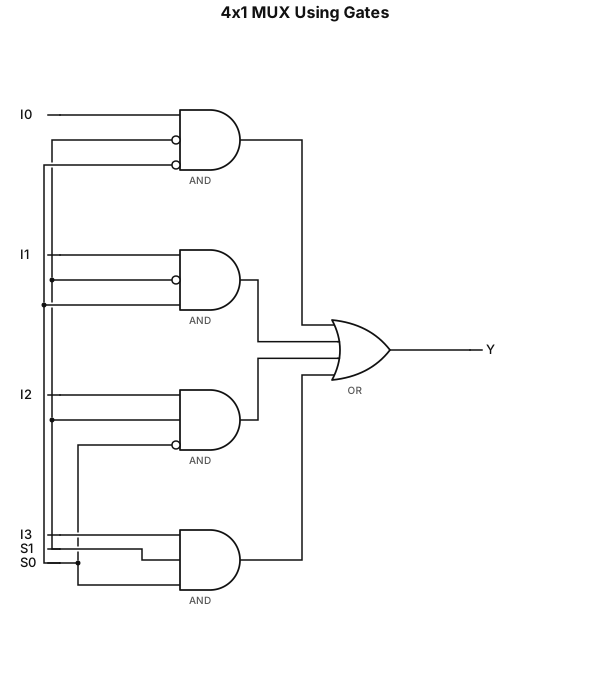
2.4 Implementation of 4×1 MUX Using Gates Truth / Selection Table S1 S0 Selected Input Output 0 0 I0 Y = I0 0 1 I1 Y = I1 1 0 I2 Y = I2 1 1 I3 Y = I3 Logic Equation Y=(I0S1S0)+(I1S1S0)+(I2S1S0)+(I3S1S0)
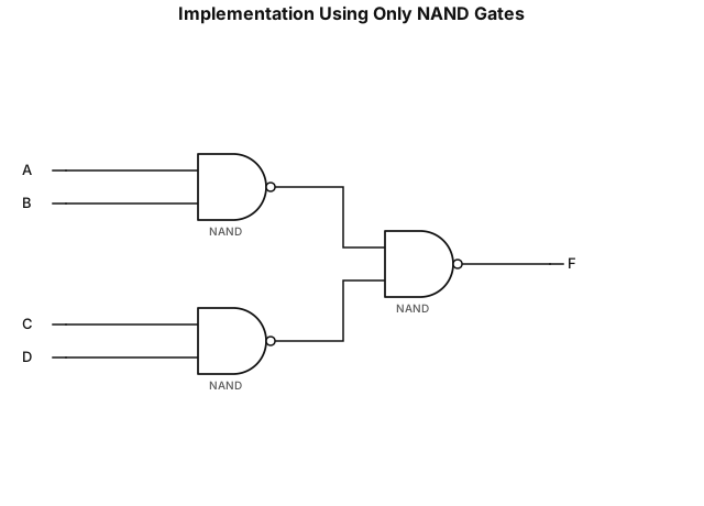
2.3 Implementation Using Only NAND Gates Given: F = AB + CD
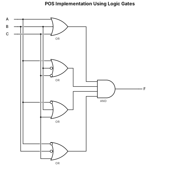
2.2 POS Implementation Using Logic Gates Given: F(A,B,C) = ΠM(0,3,4,6)