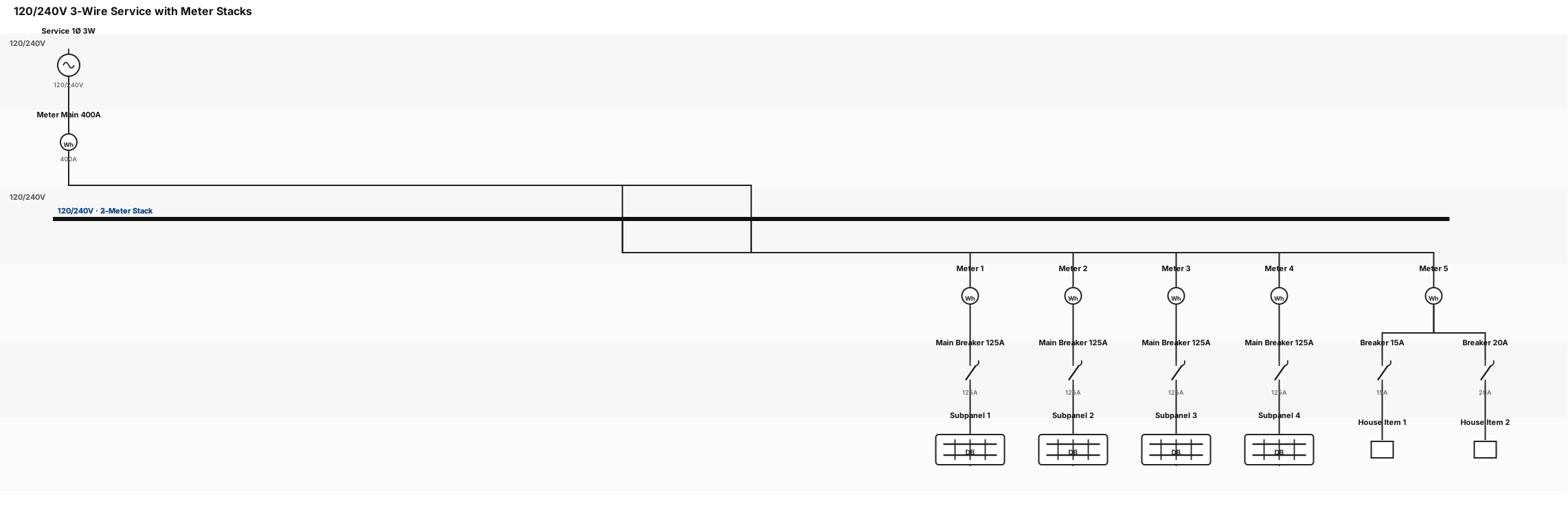
single line diagram single phase 3 wire 120/240v service feeding a 400A meter main that has a 3 meter stack with 3 meters and 125a main breakers leading to 3 subpanels and a 2 meter stack with 1 meter and a 125A main breaker leading to a subpanel and 1 meter with a 15A breaker and a 20A breaker leading to house items
NODE ARCHIVE · REAL DIAGRAM BRIEFS
Diagram Examples from Real Visitor Prompts
Browse eligible diagrams shared by FreeDiagram visitors, inspect the exact prompts, and build your own version.
Browse 1008 real creationsCOMMUNITY OUTPUTS · EXACT PROMPTS
Single Line Diagrams
Showing 25–48 of 49. No stock examples or system defaults. Choose a tool, study a real result, then reopen its prompt as your starting point.
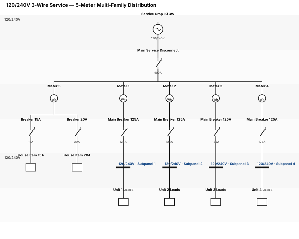
single line diagram single phase 3 wire 120/240v service feeding a 400A main that has a 3 meter stack with 3 meters and 125a main breakers leading to 3 subpanels and a 2 meter stack with 1 meter and a 125A main breaker leading to a subpanel and another meter with a 15A breaker and a 20A breaker house items
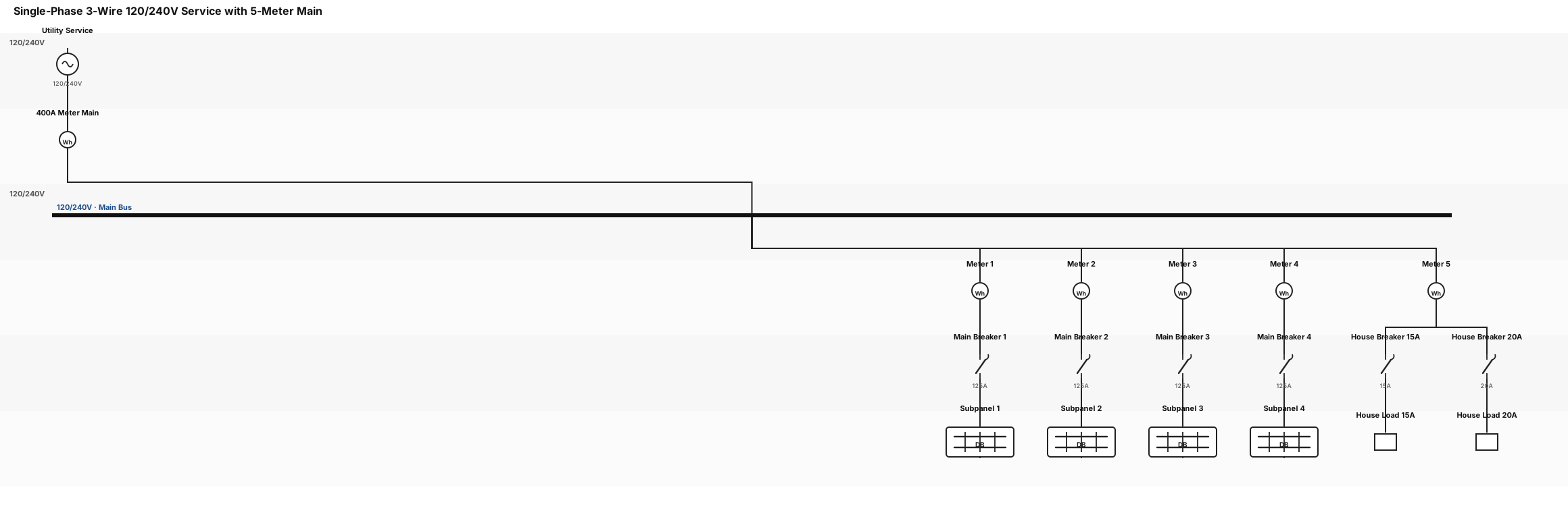
single line diagram single phase 3 wire 120/240v service feeding a 400A meter main that has 4 meters with 125a main breakers leading to 4 subpanels and 1 meter with a 15A breaker and a 20A breaker house items
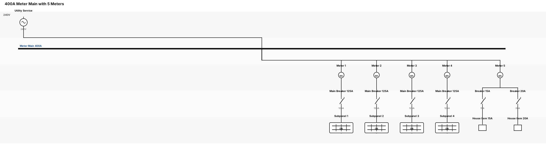
single line diagram a 400A meter main that has 4 meters with 125a main breakers leading to 4 subpanels and 1 meter with a 15A breaker and a 20A breaker house items
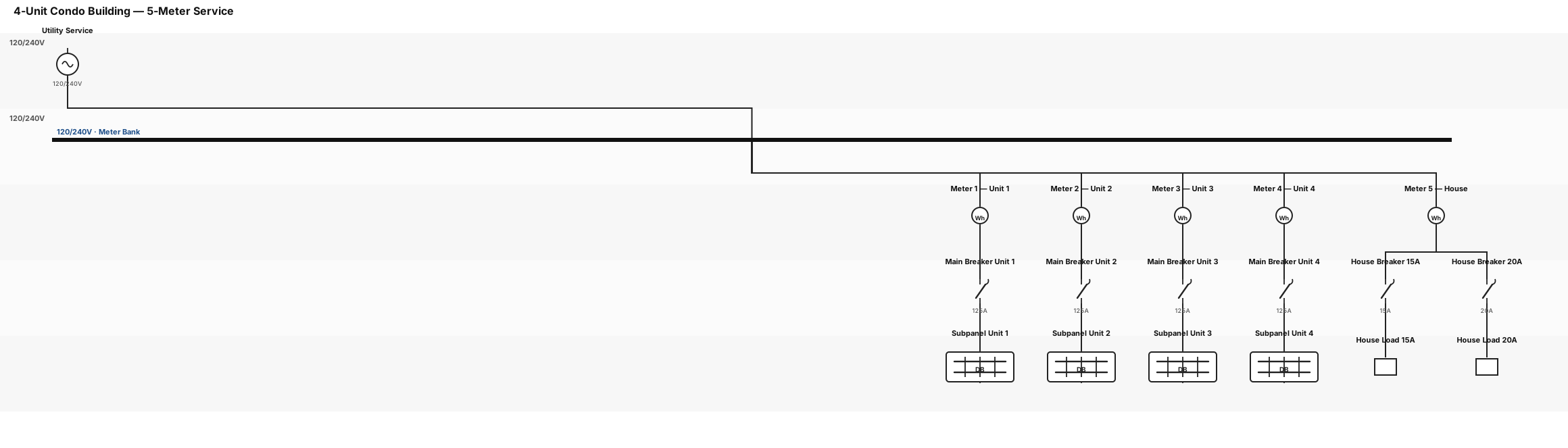
single line diagram for a 4 unit condo building with 4 meters with 125a main breakers leading to 4 subpanels and 1 meter with a 15A breaker and a 20A breaker house items
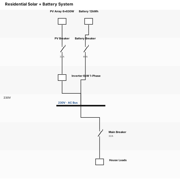
Please draw a single line diagram for a: 1. 6 kW inverter ,single phase 2. 12kwh battery 3. 6 modules 630 W each
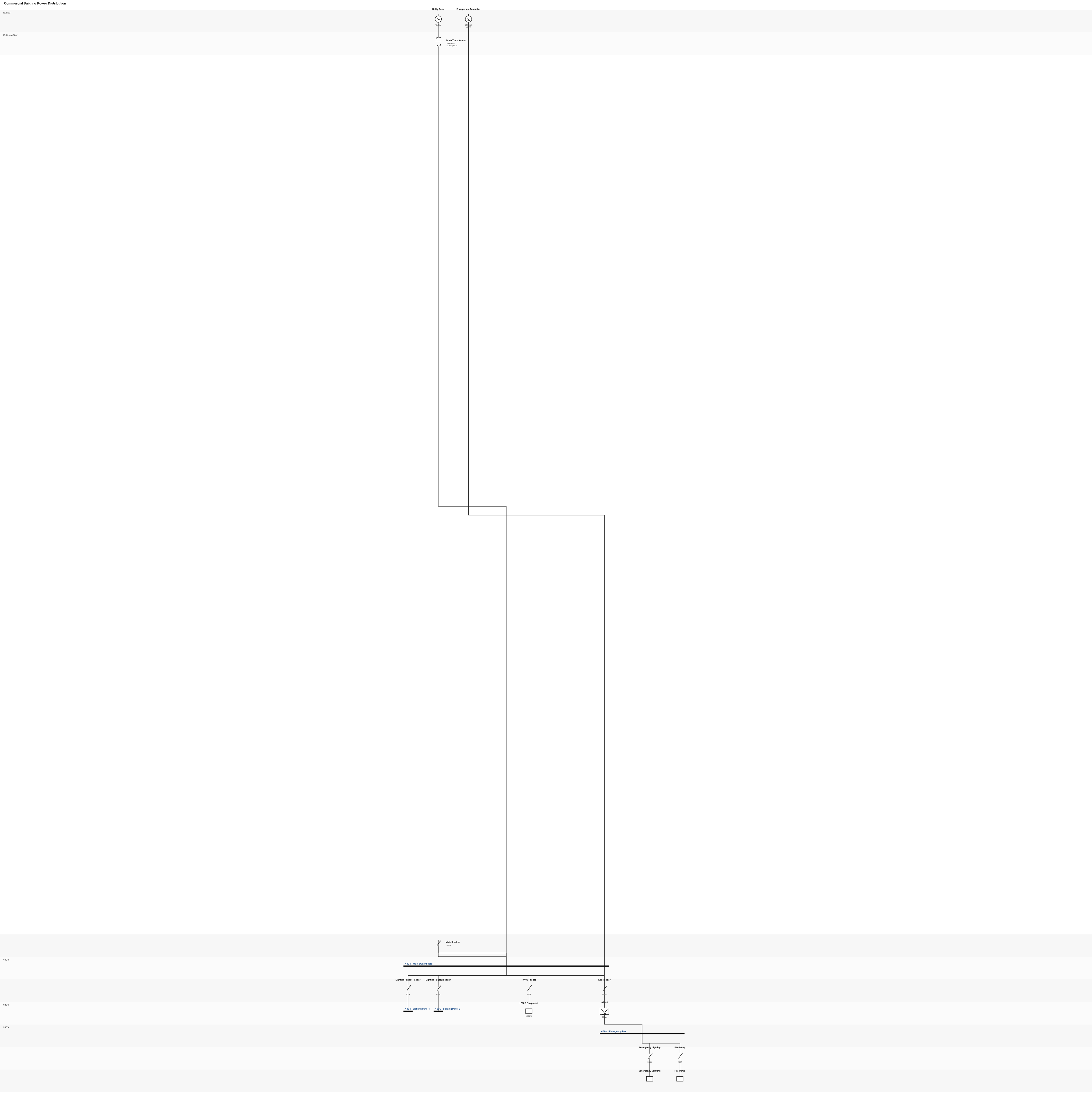
A single-line diagram for a commercial building: utility feed through a main transformer to a 480V switchboard, then to lighting panels, HVAC equipment, and an emergency generator with ATS
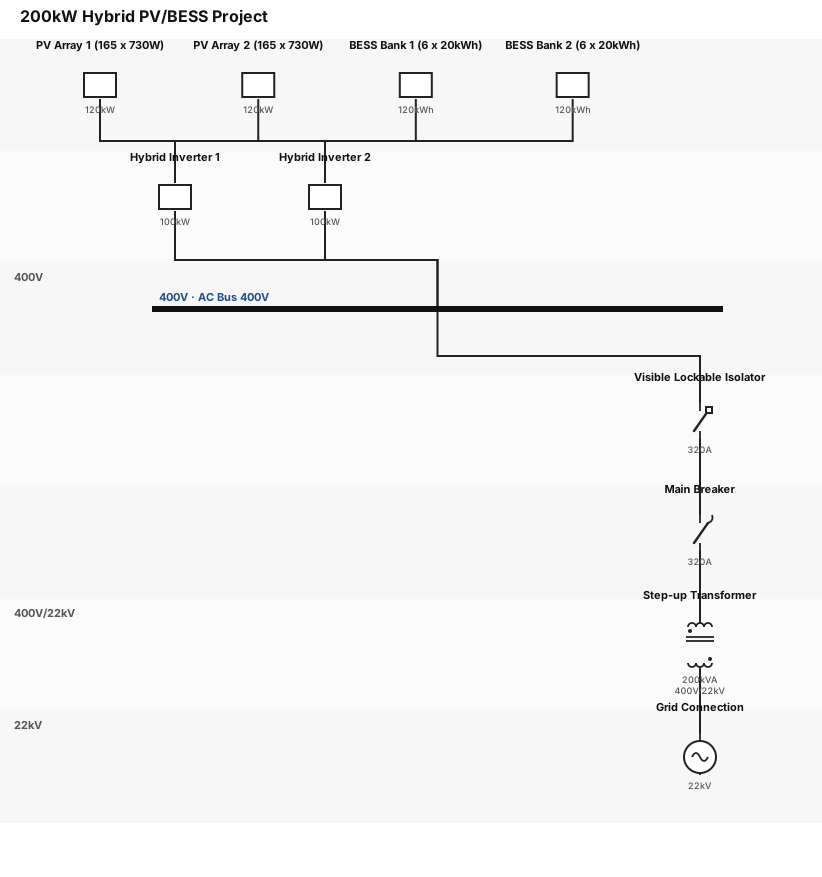
A single-line diagram for a 200kW hybrid PV/BESS project. The system contains (330 x 730W) 240kW PV modules connected to 2 x 100kW hybrid inverters and 12 units of 20kWh DC coupled storage. The inverters are connected to a 200kVA 400V/22kV transformer. There is a 320A Visible Lockage Isolator and a 320A CB between the inverters and the TX.
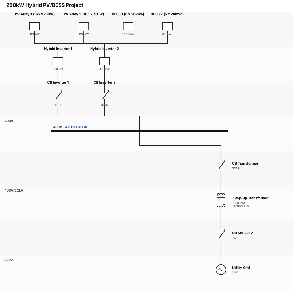
A single-line diagram for a 200kW hybrid PV/BESS project. The system contains (330 x 730W) 240kW PV modules connected to 2 x 100kW hybrid inverters and 12 units of 20kWh DC coupled storage. The inverters are connected to a 200kVA 400V/22kV transformer.
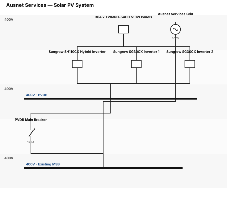
A SLD for Ausnet Services in Victoria Australia. SH110CX Hybrid Solar Inverter and 2 X Sungrow SG30CX Solar Inverters with 364 X TWMNH-54HD510W Solar Panels, connected to a PVDB then back to the existing MSB
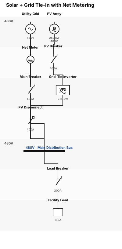
Solar plus grid tie-in with inverter and net metering disconnect
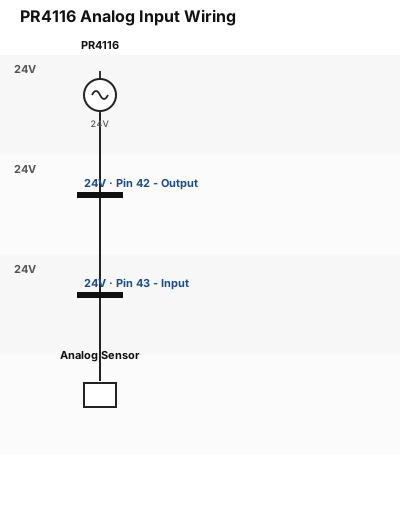
I got an PR4116, with an analog input on pin 42 and 43 with pin 42 of the pr is the output en pin 42 is then input from the sensor
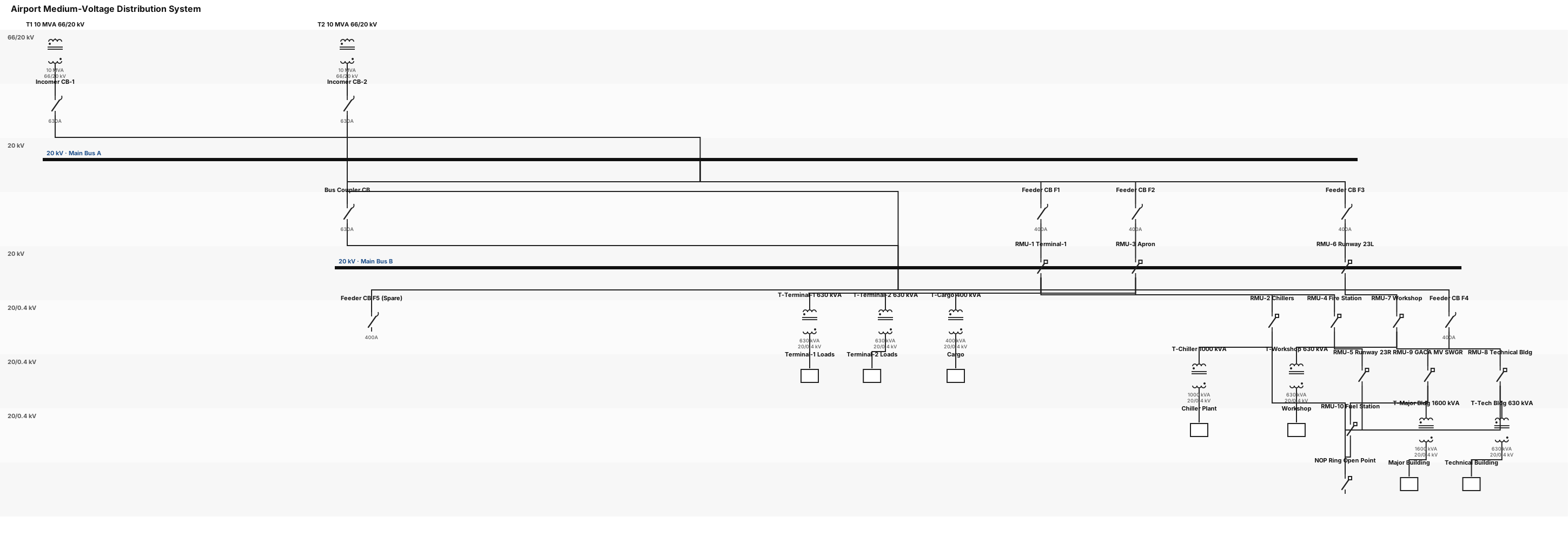
Plain Text 1 Create a medium-voltage single-line diagram for an airport power distribution system. 2 3 Source: 4 - Two 10 MVA, 66/20 kV power transformers operating in parallel. 5 - 20 kV main switchboard with bus coupler. 6 7 Outgoing feeders: 8 - F1 feeding Terminal-1 and Chillers through RMUs. 9 - F2 feeding Apron, Fire Station, and Runway 23R through RMUs. 10 - F3 feeding Runway 23L, Workshop, and Technical Building through RMUs. 11 - F4 feeding GACA MV Switchgear and Fuel Station through RMUs. 12 - F5 spare feeder. 13 14 Distribution transformers: 15 - Terminal loads: 630 kVA transformers. 16 - Chiller plant: 1000 kVA transformer. 17 - Cargo: 400 kVA transformer. 18 - Technical facilities: 630 kVA transformers. 19 - Major building load: 1600 kVA transformer. 20 21 Show: 22 - MV switchgear incomers. 23 - Busbar arrangement. 24 - Feeder circuit breakers. 25 - RMUs. 26 - Distribution transformers. 27 - Normally open point in the ring network. 28 - All equipment labels and transformer ratings.
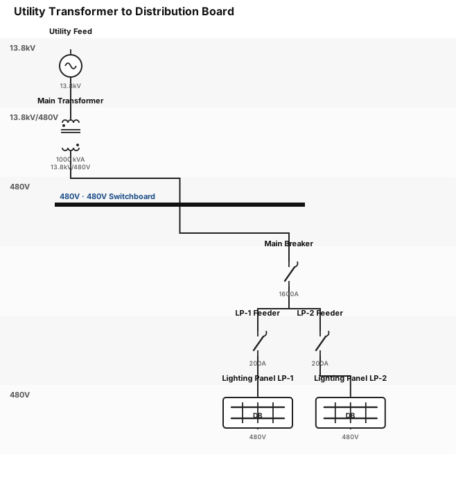
A single-line diagram for a connection from a transformer to a DB: utility feed through a main transformer to a 480V switchboard, then to lighting panels
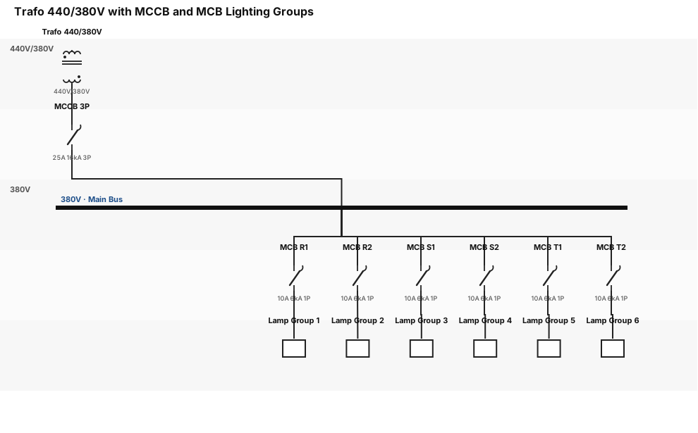
A single-line diagram with trafo 440 to 380 next to MCCB 3pole 25A 16kA, phase R to 2 MCB 1Pole 10A 6kA to lamp grup 1 and grup2 , phase S to 2 MCB 1 Pole 10A 6kA to lamp grup 3 and grup 4, and phase T to 2 mcb 1pole 10A 6kA to lamp grup 5 and grup 6
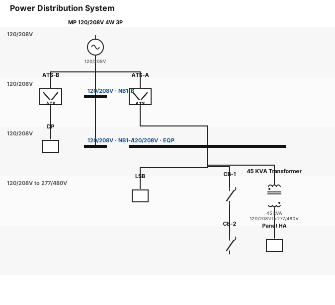
MP 120v/208v 4W 3P is normal power that feeds ATS-B, ATS-A, and NB1-B NB1-B jumps to NB1-A and ends there ATS-B feeds DP ATS- A feeds EQP EQP feeds CB-1, LSB, and a 45 KVA Transformer 120v/208v 3W 3P to 277v/480v 4W 3P CB-1 Feeds CB-2 45 KVA Transformer 120v/208v 3W 3P to 277v/480v 4W 3P feeds panel HA
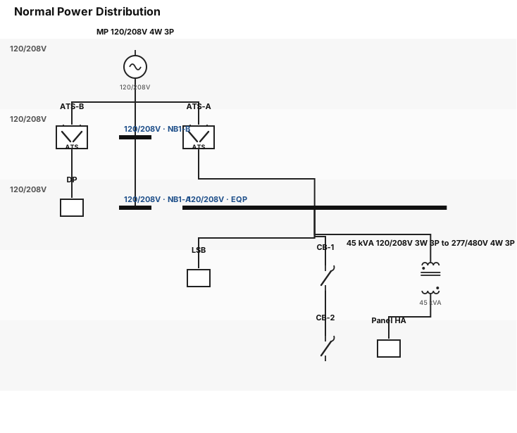
MP 120v/208v 4W 3P is normal power that feeds ATS-B, ATS-A, and NB1-B NB1-B feeds NB1-A ATS-B feeds DP ATS- A feeds EQP EQP feeds CB-1, LSB, and a 45 KVA Transformer 120v/208v 3W 3P to 277v/480v 4W 3P CB-1 Feeds CB-2 45 KVA Transformer 120v/208v 3W 3P to 277v/480v 4W 3P feeds panel HA
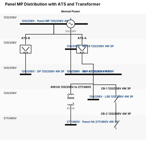
Panel MP 120v/208v 4w3P feeds into ATS-B and ATS-A ATS-B feeds DP 120v/208v 4w3P ATS-A feeds EQP120v/208v 4w3P EQP feeds a 45KVA 120v/208v 3w3P to 277v/480v 4W 3P transformer, CB-1 120v/208v 4w3P, and LSB 120v/208v 4w3P CB-1 120v/208v 4w3P feeds CB-2 120v/208v 4w3P 45KVA feeds Panel HA 277v/480v 4w3P NB1-B 120v/208v 4w3P is fed from normal power 120v/208v 4w3P undetermined where NB1-A is fed from NB1-B 120v/208v 4w3P
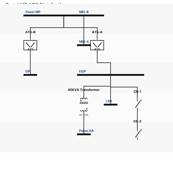
Panel MP feeds into ATS-B and ATS-A ATS-B feeds DP ATS-A feeds EQP EQP feeds a 45KVA transformer, CB-1 , and LSB CB-1 feeds CB-2 45KVA feeds Panel HA NB1-B is fed from normal power NB1-A is fed from NB1-B
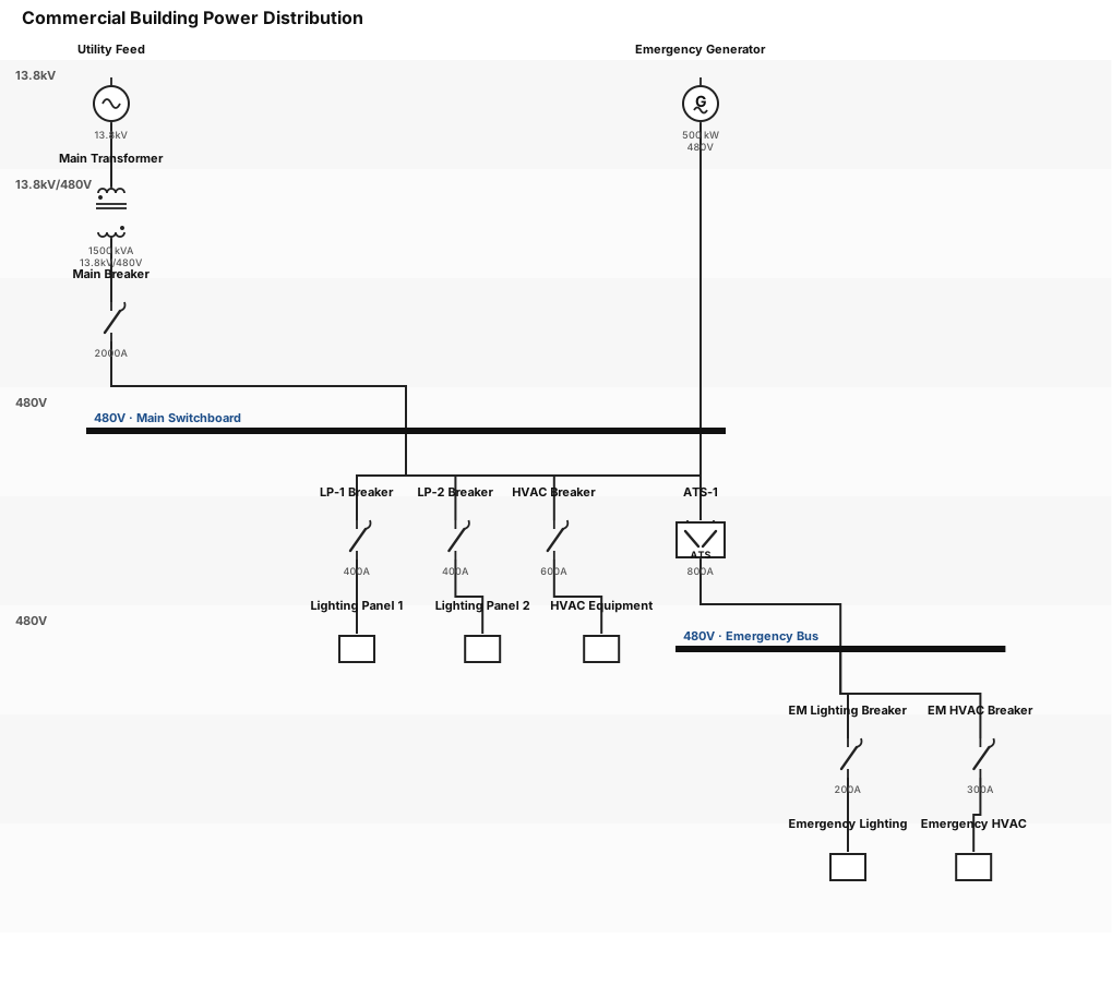
A single-line diagram for a commercial building: utility feed through a main transformer to a 480V switchboard, then to lighting panels, HVAC equipment, and an emergency generator with ATS
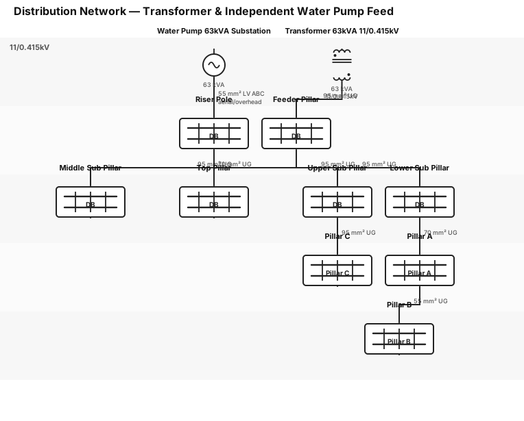
Create a single line diagram (SLD) for an electrical distribution system with the following components and connections, arranged top-to-bottom in a hierarchical layout: Transformer — 63kVA, 11/0.415kV (use standard 2-winding transformer symbol) Transformer connects to Feeder Pillar via 95sqmm UG cable Feeder Pillar has 3 outgoing feeds, all via 95sqmm UG cable, to: Lower Sub Pillar Middle Sub Pillar Upper Sub Pillar Lower Sub Pillar connects onward to Pillar A via 70sqmm UG cable Pillar A connects onward to Pillar B via 55sqmm UG cable Upper Sub Pillar connects onward to Pillar C via 95sqmm UG cable Middle Sub Pillar has no further downstream connection Separately, show a second independent feed (not connected to the transformer above): Water Pump 63kVA Substation (separate source) connects to a Riser Pole via LV ABC 55sqmm aerial cable (label this segment as aerial/overhead) Riser Pole connects to Top Pillar via 70sqmm UG cable (underground) Use standard electrical/panel symbols where available (transformer symbol, distribution panel/pillar boxes with bus bar lines, breaker marks at connection points). Label every cable segment with its size and type (UG = underground, LV ABC = aerial bunched cable). Visually separate the water pump/top pillar branch from the main transformer branch to show they are electrically independent systems on the same drawing.
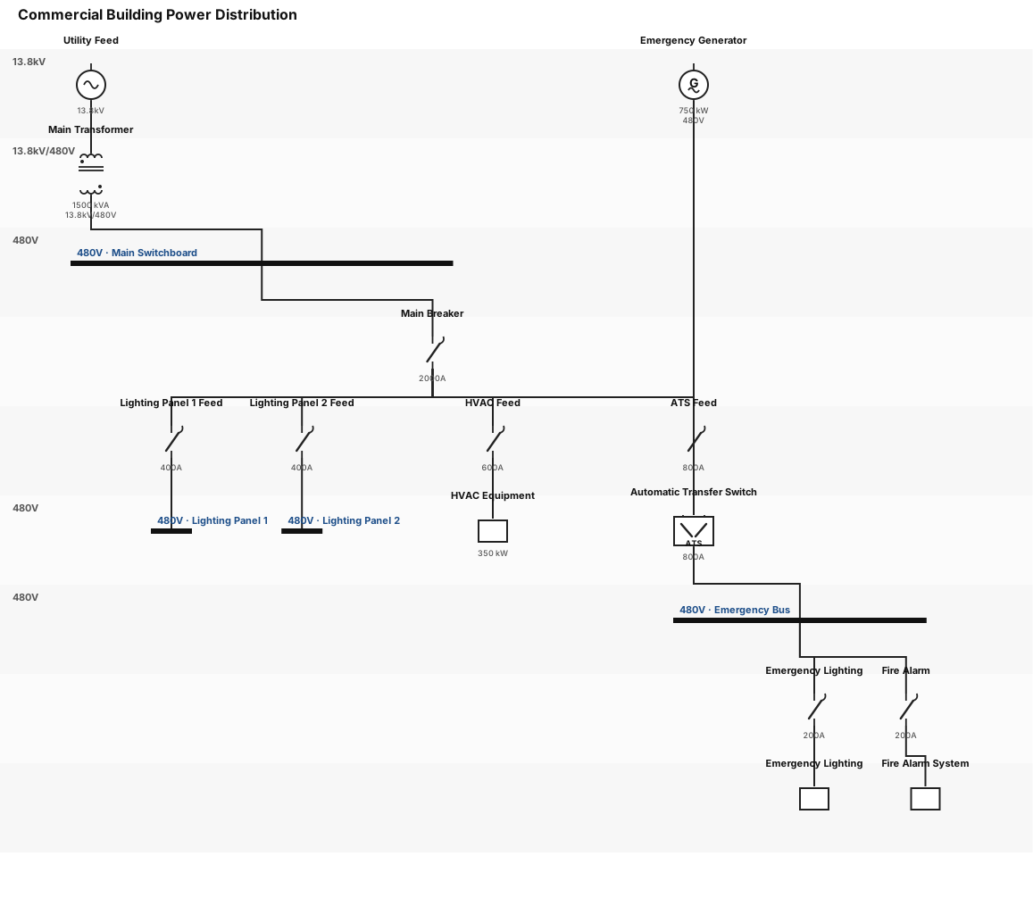
A single-line diagram for a commercial building: utility feed through a main transformer to a 480V switchboard, then to lighting panels, HVAC equipment, and an emergency generator with ATS
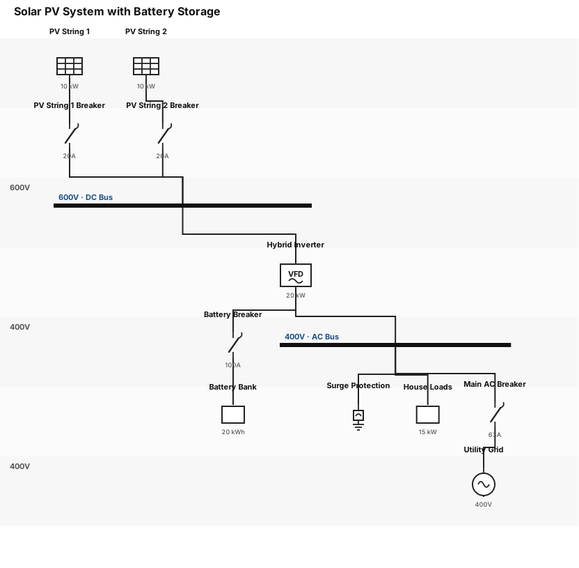
Solar PV system, with 2 strings of panels connected to an Inverter. Battery system and protection equipments.
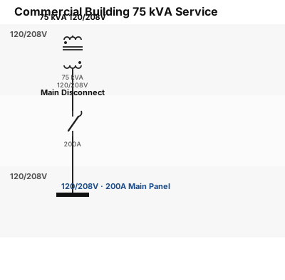
A single-line diagram for a commercial building: Transformer 75 kVA 120/208, 200A main disconnect and 200A main panel. If any additional information is needed let me know.
Focused examples and prompt ideas
Start with the complete visitor wall above, then use these focused collections when you want a narrower subject and more prompt context.
The first curated collection is being prepared.