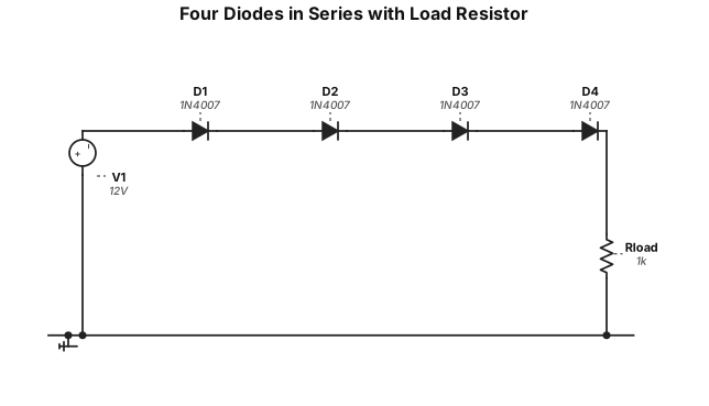
4 diodes in series with a load resistor and a power source
NODE ARCHIVE · REAL DIAGRAM BRIEFS
Diagram Examples from Real Visitor Prompts
Browse eligible diagrams shared by FreeDiagram visitors, inspect the exact prompts, and build your own version.
Browse 3261 real creationsCOMMUNITY OUTPUTS · EXACT PROMPTS
Circuit Diagrams
Showing 49–72 of 270. No stock examples or system defaults. Choose a tool, study a real result, then reopen its prompt as your starting point.
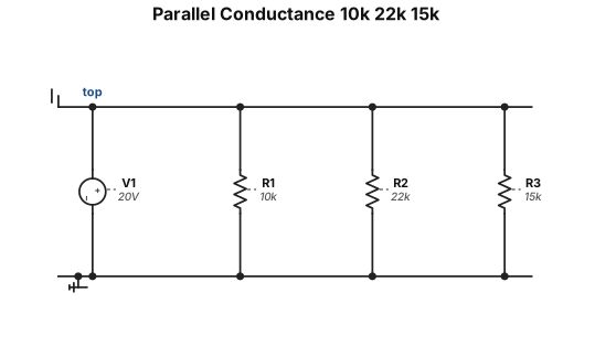
2. Find the total conductance of a 10Kohms, 22Kohms, and 15Kohms resistor connected in parallel. How much current will flow if a 20V source is connected to this circuit? 3 marks
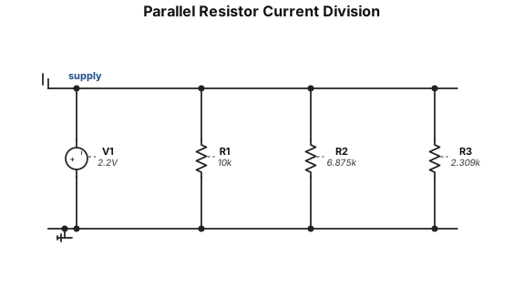
Questions: 1. A source connected to three resistors in parallel supplies a total current of 3.5mA. One resistor is 10Kohms and has a voltage drop of 2.2V. Second resistor has a current of 320 micro-amps. How much current is flowing through the third resistor? 3 marks
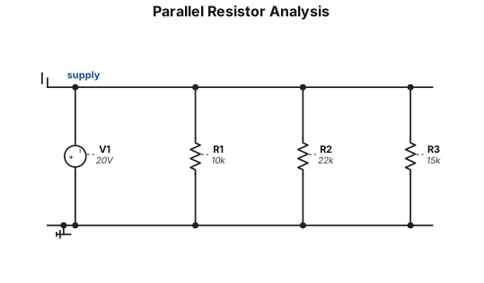
Questions: 1. A source connected to three resistors in parallel supplies a total current of 3.5mA. One resistor is 10Kohms and has a voltage drop of 2.2V. Second resistor has a current of 320 micro-amps. How much current is flowing through the third resistor? 3 marks 2. Find the total conductance of a 10Kohms, 22Kohms, and 15Kohms resistor connected in parallel. How much current will flow if a 20V source is connected to this circuit? 3 marks 3. Three resistors connected in parallel have an equivalent resistance of 2.5Kohms. R1 has a resistance of 15Kohms, R2 has a voltage drop of 25V, and R3 produces heat at a rate of 25mW. Determine R2 and R3. 3 mark
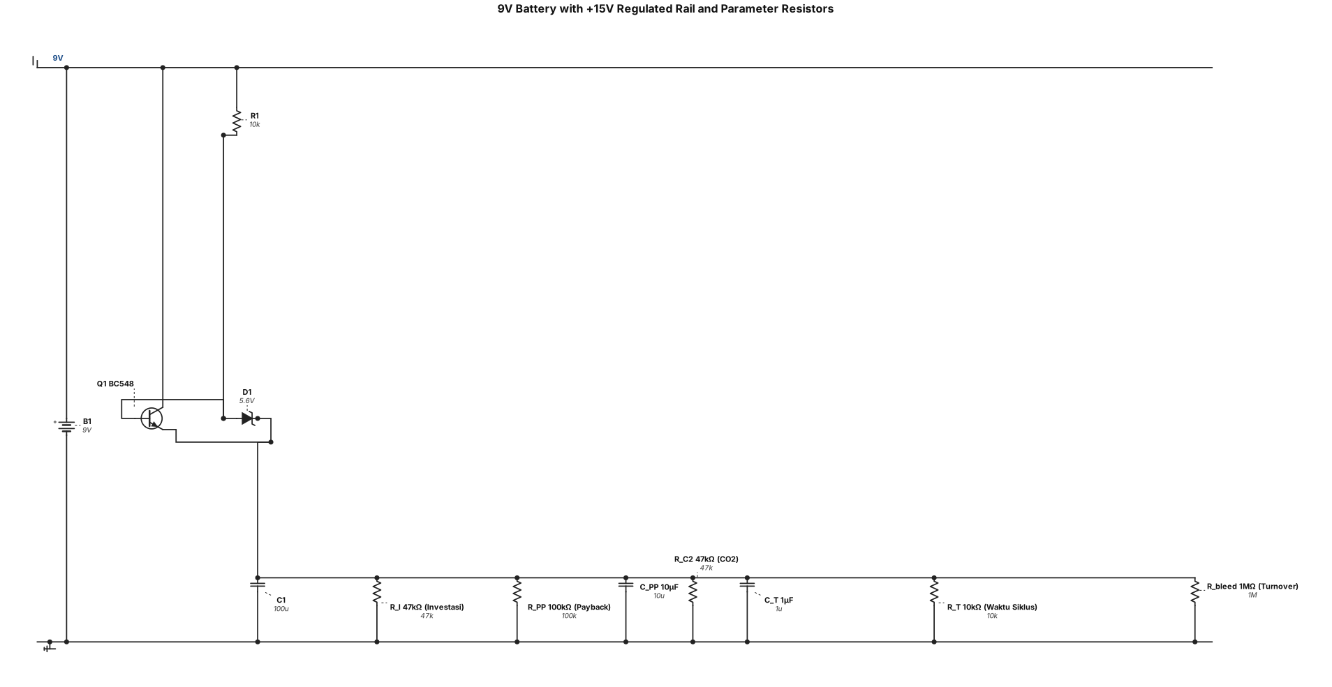
Analog circuit: a 9V battery as main power supply. +15V rail derived through a BC548 regulator (emitter follower). Fifteen fixed resistors representing internal parameters: R_I=47kΩ (Investasi), R_PP=100kΩ with C_PP=10μF (Payback), R_C2=47kΩ (CO2), R_T=10kΩ with C_T=1μF (Waktu Siklus), R_bleed=1MΩ (Turnover). Each labeled with parameter name and value. All connected to +15V rail and ground. Label clearly.
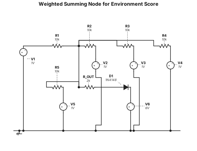
Analog circuit: a weighted summing node for environment score. Five input voltages (V4_Limbah, V_C2_CO2, V_Lk_TenagaLokal, V_D_JarakAir, V_Rek_Reklamasi) each connected through a 10kΩ resistor to a common summing node. The summing node connected through R_OUT=2kΩ to output V_ENV. A 1N4148 diode from V_ENV to +6V reference (threshold clamp). Label all resistors 10kΩ, R_OUT=2kΩ, diode 1N4148.
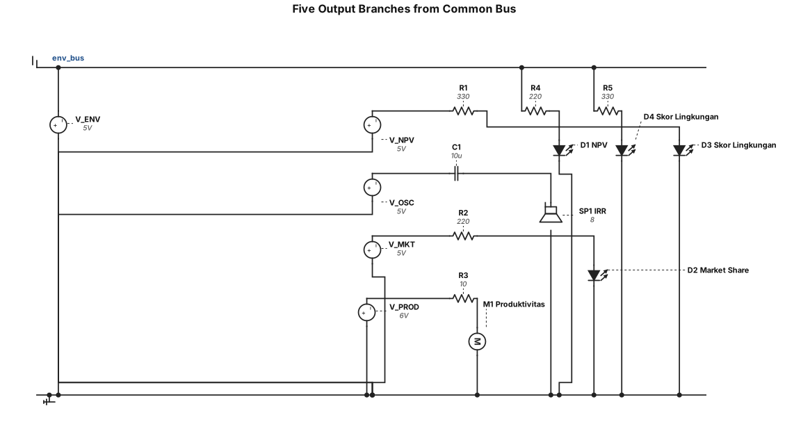
Analog circuit: five output branches from a common bus. Branch 1: V_NPV through R=330Ω to a red LED (anode to V_NPV, cathode to ground), labeled "NPV". Branch 2: oscillator output through C=10μF coupling to an 8Ω speaker, labeled "IRR". Branch 3: V_MKT through R=220Ω to a green LED, labeled "Market Share". Branch 4: V_PROD through R=10Ω to a 6V DC motor (labeled "Produktivitas"). Branch 5: V_ENV through R1=220Ω to a blue LED and R2=330Ω to an orange LED (both cathodes to ground), labeled "Skor Lingkungan". Label all components.
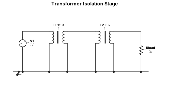
Analog circuit: a transformer with primary winding N1=100 turns and secondary winding N2=1000 turns (1:10 ratio). Primary connected to V_AMP input. Secondary output labeled V_ISOLATED. A second transformer with 1:K ratio (K variable, shown as 1:5 turns ratio as example). Label both transformers with turns ratio. Input labeled "V_AMP", output labeled "V_ISOLATED = V_AMP × K".
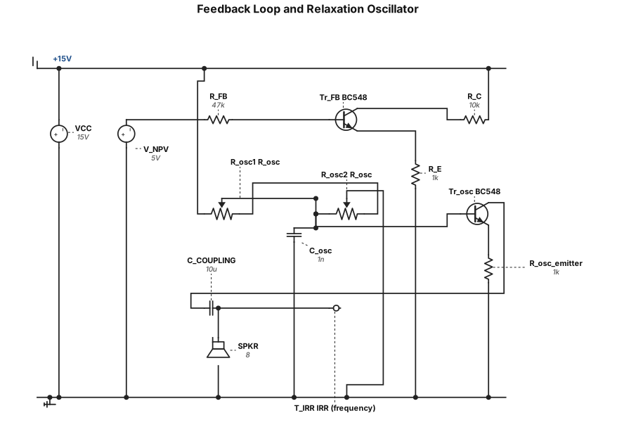
Analog circuit: a feedback loop and relaxation oscillator. V_NPV from previous stage connected through R_FB=47kΩ to the base of a BC548 NPN transistor (Tr_FB). Tr_FB emitter through R_E=1kΩ to ground, collector to +15V. A relaxation oscillator circuit: second BC548 transistor with R_osc=10kΩ (potentiometer) and C_osc=1nF forming a timing loop. Oscillator output coupled through C_COUPLING=10μF to an 8Ω speaker (SPKR). Label all components with values. Output labeled "IRR (frequency)".
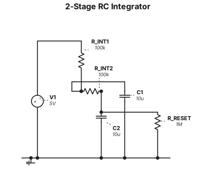
Analog circuit: a 2-stage RC integrator. Input V_DRAIN from previous stage connected through R_INT1=100kΩ to a node with C1=10μF to ground (first integrator stage). First stage output connected through R_INT2=100kΩ to a second node with C2=10μF to ground (second integrator stage). A reset resistor R_RESET=1MΩ from second stage output to ground. Output labeled V_NPV at second stage. Label all components with values.
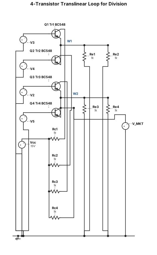
Analog circuit: a 4-transistor translinear loop for division. Four BC548 NPN transistors (Tr1, Tr2, Tr3, Tr4) arranged in a 2x2 loop. Tr1 and Tr2 emitters tied together, Tr3 and Tr4 emitters tied together. Tr1 base receives input V3, Tr2 base receives input V4, Tr3 base receives input V2, Tr4 base receives input V5. Each collector has a 1kΩ resistor to +15V. Each emitter has a 1kΩ resistor to ground. Output V_MKT taken at Tr4 collector. Label all transistors BC548, all resistors 1kΩ.
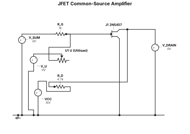
Analog circuit: a JFET 2N5457 in common-source configuration. Gate connected through 1kΩ resistor (R_G) to input V_SUM. A 10kΩ potentiometer labeled "U (Utilisasi)" provides gate bias voltage V_U. Drain connected through 4.7kΩ resistor (R_D) to +15V supply. Source connected to ground. Output V_DRAIN taken at drain node. Label all components: JFET type 2N5457, R_G=1kΩ, R_D=4.7kΩ, pot U=10kΩ.
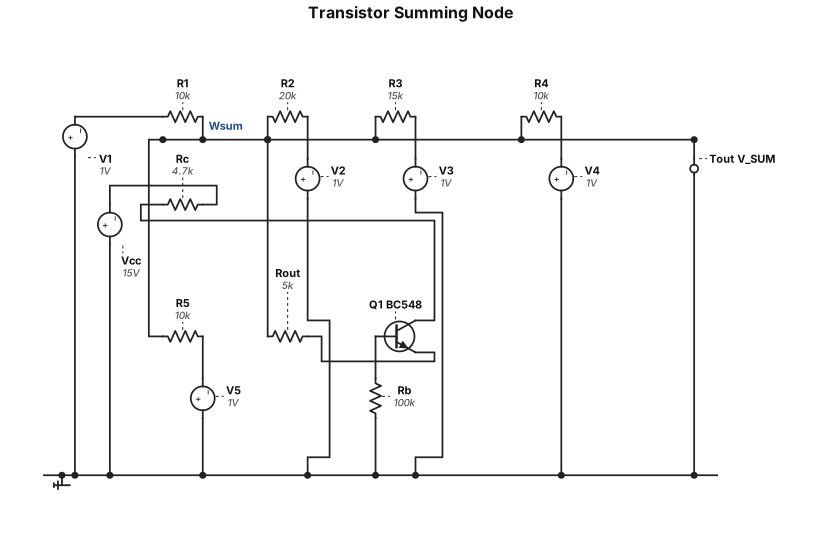
Analog circuit: a summing node (virtual ground) using an inverting op-amp configuration replaced by a single BC548 NPN transistor as current sink. Five input voltages V1 through V5 each connected through a resistor (R1=10kΩ, R2=20kΩ, R3=15kΩ, R4=10kΩ, R5=10kΩ) to a common node. The common node connects through R_OUT=5kΩ to a BC548 emitter. Collector to +15V through 4.7kΩ. Base biased through 100kΩ to ground. Output labeled V_SUM at the common node. Label all resistors with values.
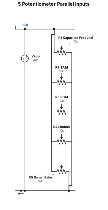
Analog circuit: 5 potentiometers (10kΩ each) connected in parallel to a +15V supply, each wiper output labeled V1 through V5. V1 labeled "Kapasitas Produksi", V2 labeled "TAM", V3 labeled "SDM", V4 labeled "Limbah", V5 labeled "Bahan Baku". All bottom terminals connected to ground. Clean schematic with component values labeled.
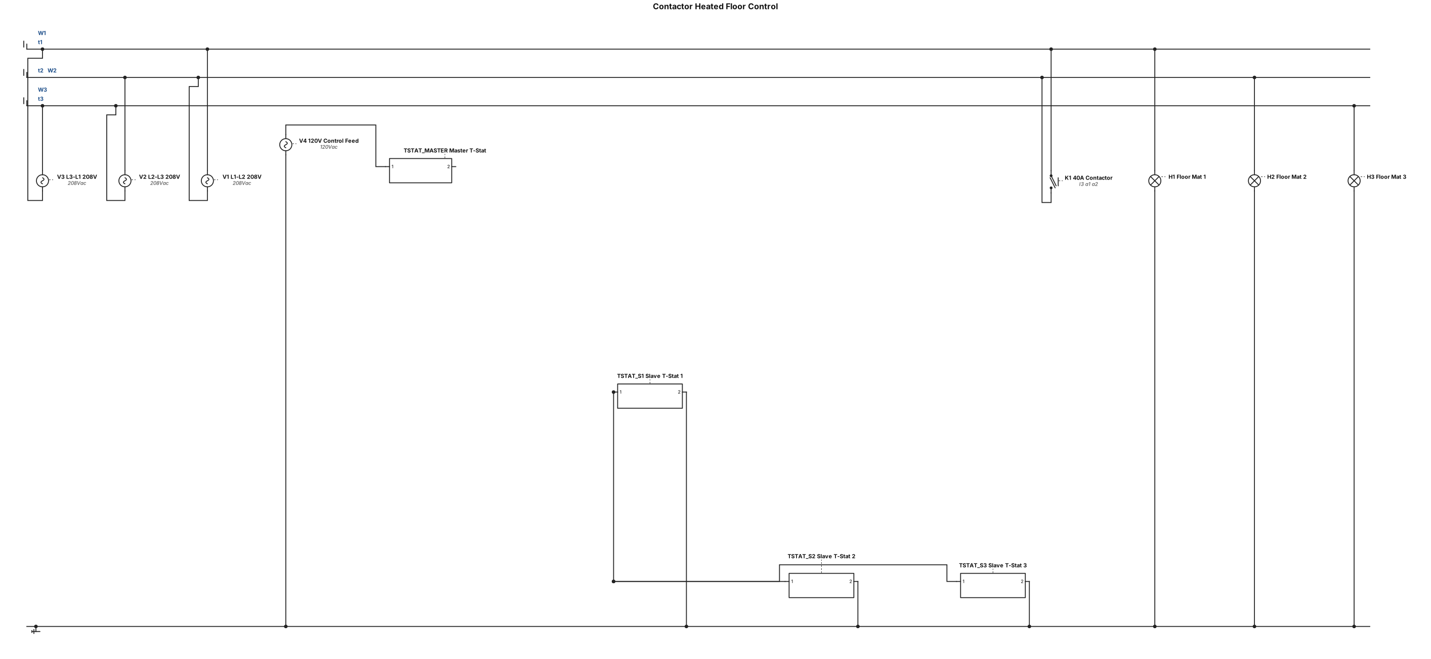
40amp contactor 208v feed l1,l2,l3 with a 15amp coil a1,a2 controlled by a master t-stat 120v feed with three slave thermostats 120v feeds powering four radient heat floor mats t1,t2,t3 off contactor
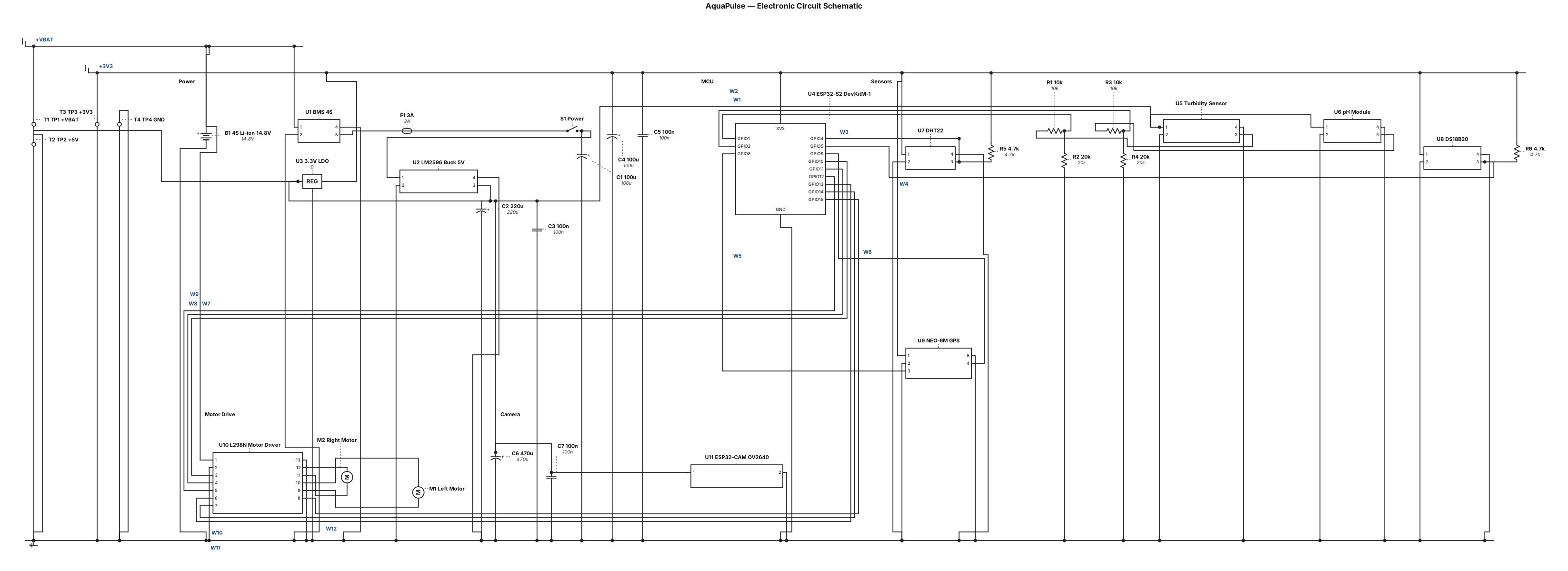
Draw a PURE ELECTRONIC CIRCUIT SCHEMATIC for my AquaPulse water-quality robot. Absolutely no block diagrams or flowcharts. Use standard circuit symbols and actual electrical wires: battery-cell symbols, zigzag resistors, fuse, switch, ground, voltage rails, connector pins and junction dots. Components: - 4S 14.8 V lithium-ion battery, BMS, 3 A fuse and switch. - LM2596 buck converter providing regulated 5 V. - ESP32-S2 DevKitM-1 with individually labelled GPIO pins. - Turbidity sensor AO to GPIO1 through a voltage divider. - pH module PO to GPIO2 through a voltage divider. - DHT22 DATA to GPIO4. - DS18B20 DQ to GPIO5 with 4.7 kΩ pull-up to 3.3 V. - NEO-6M GPS TX to GPIO8 and RX to GPIO9. - L298N motor driver: ENA GPIO10, IN1 GPIO11, IN2 GPIO12, IN3 GPIO13, IN4 GPIO14, ENB GPIO15. - Two DC motors connected to OUT1/OUT2 and OUT3/OUT4. - Separate ESP32-CAM with integrated OV2640 camera, powered from a suitable supply. Use named nets such as +VBAT, +5V, +3V3 and GND to avoid long crossing wires. Draw components using real electronic symbols, not rectangular functional blocks. Use a landscape A3 schematic with readable labels and a white background. Show Wi-Fi communication only as a separate dashed annotation, never as an electrical wire. Mark all unverified connections as provisional. Title: AquaPulse — Electronic Circuit Schematic.
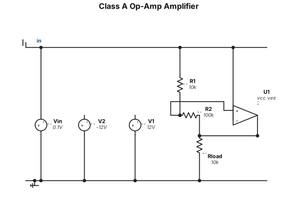
Clas A op amp circuit
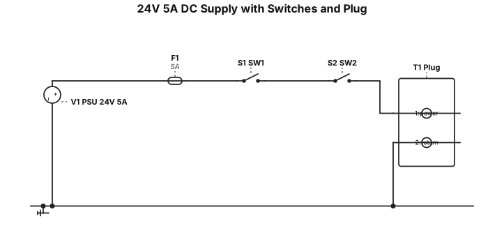
A 24V, 5A DC power supply connecting to two switches and then to a plug
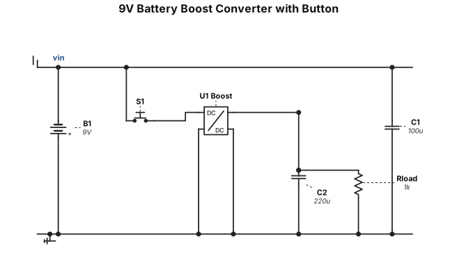
9 vlot battary going into a boost converter with a button
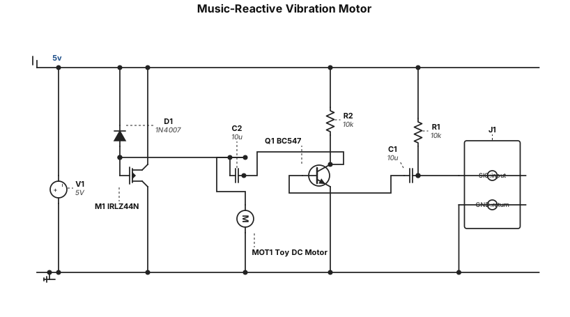
- 1 × BC547 transistor - 1 × IRLZ44N MOSFET - 1 × 1N4007 diode - 1 × 10 µF capacitor - 1 × 10 kΩ resistor - A few jumper wires We will use the 5 V power adapter, the toy DC motor, and the AUX cable. 1. AUX input: Receives the audio signal from a phone or computer. 2. BC547 transistor: Amplifies the weak audio signal. 3. 10 µF capacitor: Couples the audio signal to the MOSFET's gate. 4. IRLZ44N MOSFET: Controls the current flowing through the motor. 5. 1N4007 diode: Protects the circuit from voltage spikes generated by the motor. 6. 5 V adapter: Powers the motor and circuit. Goal: The DC motor vibrates in response to the music, creating a simple music-reactive vibration effect.
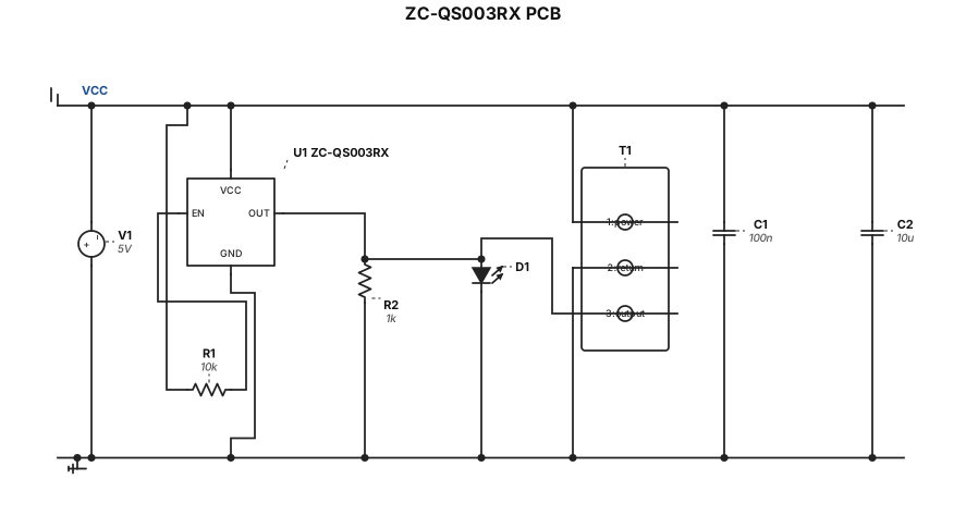
ZC-QS003RX pcb schematic
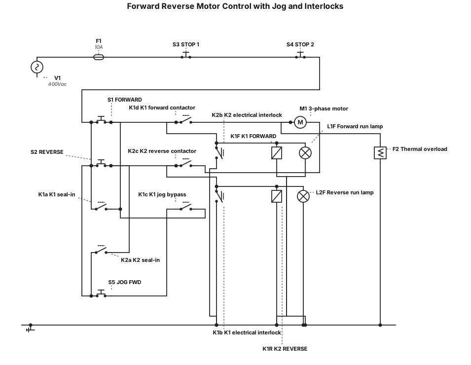
Generate a circuit diagram for 1. Motor can be started FORWARD by pushbutton S1. 2. Motor can be started REVERSE by pushbutton S2. 3. Motor can be stopped by operating either pushbutton S3 or S4. 4. Indicator lamp L1 indicates the motor is running in the forward direction. 5. Indicator lamp L2 indicates the motor is running in the reverse direction. 6. Jogging control for the motor in the forward direction only using S5. 7. Mechanical and electrical interlocking is to be used. 8. Motor is to be protected by thermal overload.
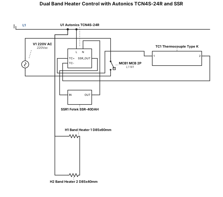
buatkan diagram ini, tapi ganti heaternya menjadi 2 band heater dengan masing-masing daya 500w 220v, ukuran heater pertama d85x60mm dan heater kedua d85x40mm, dan modul thermostatnya menggunakan autonics tcn4s-24r serta ssr fotek 40dah, ganti sensor thermocouple type k dan output dari autonics ssr out, hilangkan tombol atau saklar. buat awalan dari listrik 220v dan mcb 2 pole
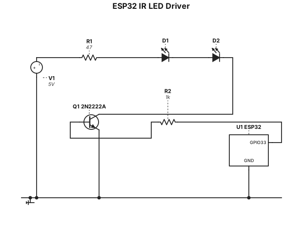
ESP32 5V (VIN) ── 39Ω or 47Ω ── IR LED 1 ── IR LED 2 ── 2N2222A collector 2N2222A emitter ── GND GPIO33 ── 1k ── 2N2222A base