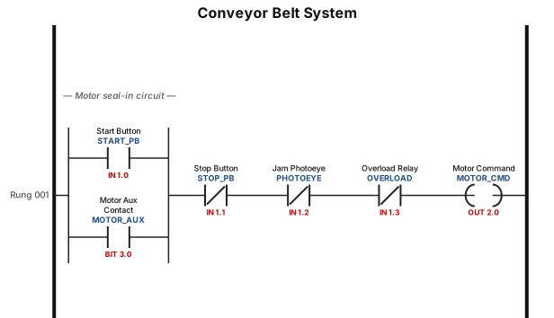
A ladder logic program for a conveyor belt system: start button seals in the motor, a photoeye stops the belt when a jam is detected, and an overload relay trips the circuit
NODE ARCHIVE · REAL DIAGRAM BRIEFS
Diagram Examples from Real Visitor Prompts
Browse eligible diagrams shared by FreeDiagram visitors, inspect the exact prompts, and build your own version.
Browse 3261 real creationsCOMMUNITY OUTPUTS · EXACT PROMPTS
Ladder Logic
Showing 49–57 of 57. No stock examples or system defaults. Choose a tool, study a real result, then reopen its prompt as your starting point.
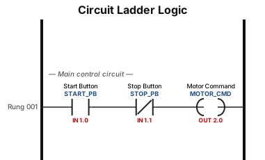
P3: Draw the ladder logic diagram for given circuit, use a suitable software tool/platform.
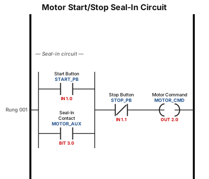
A motor start/stop seal-in circuit with a normally open start button, a normally closed stop button, and a seal-in contact around the start button
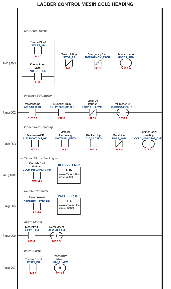
LADDER CONTROL MESIN COLD HEADING
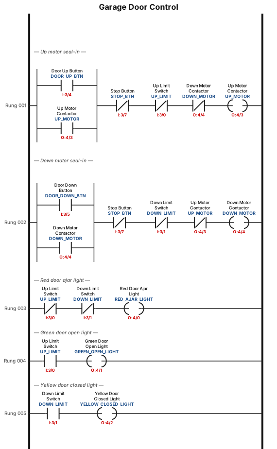
A motorized overhead garage door is to be operated automatically to preset open and closed positions. The field devices include one of each of the following: • Reversing motor contactor for the up and down directions. • Normally open down limit switch to sense when the door is fully closed. • Normally open-held closed up-limit switch to sense when the door is fully opened. • Normally open door up button for the up direction. • Normally open door down button for the down direction. • Normally closed door stop button for stopping the door. • Red door ajar light to signal when the door is partially open. • Green door open light to signal when the door is fully open. • Yellow door closed light to signal when the door is fully closed. The sequence of operation requires that: • When the up button is pushed, the up-motor contactor energizes and the door travels upward until the up-limit switch is actuated. • When the down button is pushed, the down motor contactor energizes and the door travels down until the down limit switch is actuated. • When the stop button is pushed, the motor stops. The motor must be stopped before it can change direction Tag Device Type Function I:3/0 Up limit NO-held closed Detects when door is fully open I:3/1 Down limit NO Detects when door is fully closed I:3/4 Door up button NO Command to raise door I:3/5 Door down button NO Command to lower door I:3/7 Stop door button NC Stops motor immediately Tag Device Function O:4/0 Red light Door ajar (neither limit made) O:4/1 Green light Door fully open O:4/2 Yellow light Door fully closed O:4/3 Up motor contactor Energizes motor upward O:4/4 Down motor contactor Energizes motor downward
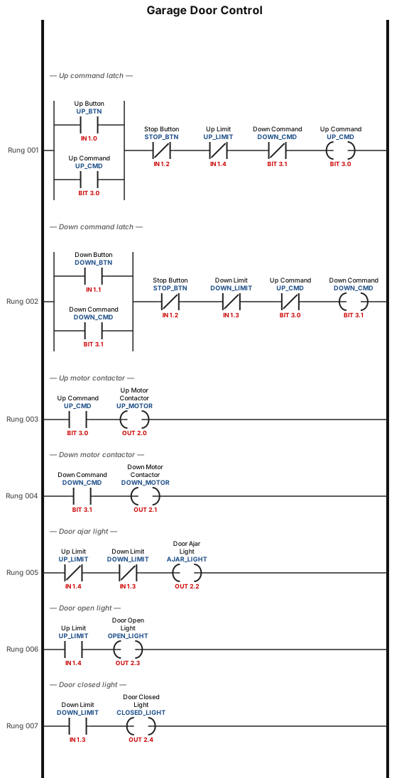
A motorized overhead garage door is to be operated automatically to preset open and closed positions. The field devices include one of each of the following: • Reversing motor contactor for the up and down directions. • Normally open down limit switch to sense when the door is fully closed. • Normally open-held closed up-limit switch to sense when the door is fully opened. • Normally open door up button for the up direction. • Normally open door down button for the down direction. • Normally closed door stop button for stopping the door. • Red door ajar light to signal when the door is partially open. • Green door open light to signal when the door is fully open. • Yellow door closed light to signal when the door is fully closed. The sequence of operation requires that: • When the up button is pushed, the up-motor contactor energizes and the door travels upward until the up-limit switch is actuated. • When the down button is pushed, the down motor contactor energizes and the door travels down until the down limit switch is actuated. • When the stop button is pushed, the motor stops. The motor must be stopped before it can change direction.
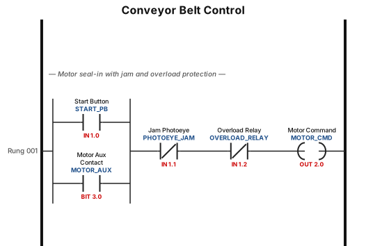
A ladder logic program for a conveyor belt system: start button seals in the motor, a photoeye stops the belt when a jam is detected, and an overload relay trips the circuit
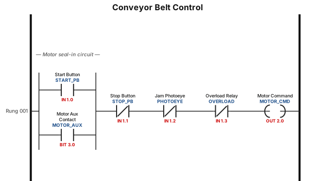
A ladder logic program for a conveyor belt system: start button seals in the motor, a photoeye stops the belt when a jam is detected, and an overload relay trips the circuit

By pressing the start button: motors M1, M2, and M3 all run together. After 3 seconds: M1 stops and M4 starts. After 3 seconds: M2 stops and M1 starts. After 3 seconds: M3 stops and M2 starts. After 3 seconds: M4 stops and M3 starts. This cycle repeats continuously (a rotation among the 4 motors, with 3 always running at the same time, and every 3 seconds one motor changes). There are three important execution conditions: Without using a comparator instruction. The start button has no effect after the process begins (it is not a stop button). State must be preserved when stopping (resume from the last state when restarted). Implementation is required using a Ladder Diagram.