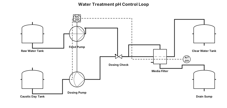
Water treatment loop with pH control and dosing pump
NODE ARCHIVE · REAL DIAGRAM BRIEFS
Diagram Examples from Real Visitor Prompts
Browse eligible diagrams shared by FreeDiagram visitors, inspect the exact prompts, and build your own version.
Browse 3257 real creationsCOMMUNITY OUTPUTS · EXACT PROMPTS
Pid
Showing 49–72 of 142. No stock examples or system defaults. Choose a tool, study a real result, then reopen its prompt as your starting point.
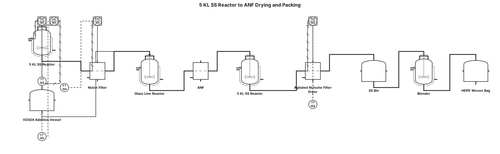
Make P&ID for 5 KL Stainless steel reactor then mass transfer Nutch filter (NF) then clear filtrate from NF transfer to Glass line reactor (GLR) having provision H2SO4 addition vessel the Reaction mass from GLR transfer to ANF for filtration. After ANF solid mass transfer 5 KL stainless reactor having water charing line then filter the mass and dry in ANDF agitated nutche filter and unload material in SS bin. Solid material tranfer in to blender further shifting and final packed in to HDPE woven bag
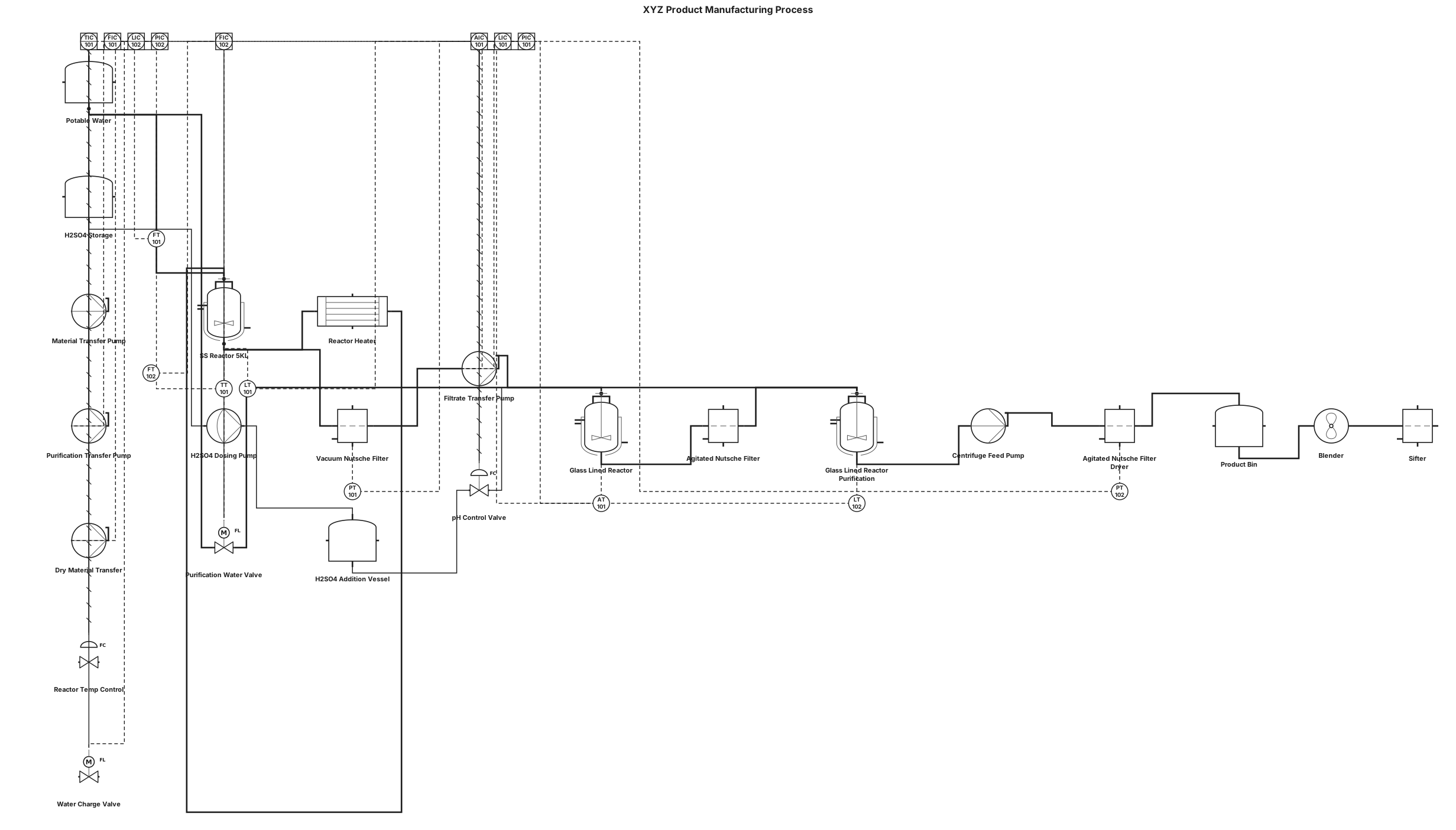
Process Description XYZ product: Charge 875 kg potassium hydroxide further charge 3750 L of potable water and Charge 2 Chloro 5 Nitro Benzoic Acid (CNBA) 625 kg in to SS reactor (5 KL). Apply heating and attend temperature 130 -140°C after that maintain at 130 - 140°C for 8-10 Hrs. Cool the reaction mass at 45 - 50°C charge potable water 2500L and heat the reaction mass up to 70°C and filter through Vacuum Nutsche Filter (VNF). Transfer clear filtrate in to Glass line reactor then Adjust pH below 2.0 by adding H2SO4 (Addition vessel) further cool the mass and filtered through Agitated nutche (ANF). Unload wet material and transfer material in to glass line reactor and then charge water for purification then material transfer to Agitated nutch filter dryer (ANFD) after dried material unload in to bin and then transfer in to Blender then transfer to sifting Sifter and finallly pack Purification: Send wet cake for purification. Charge wet cake and 5 times water in reactor and stir for 1 hr. Centrifuge the material lot wise washing with 200Ltrs water for each lot. Send wet cake for HPLC analysis. If HPLC does not comply proceed for 2nd purification. If result complies proceed for drying.
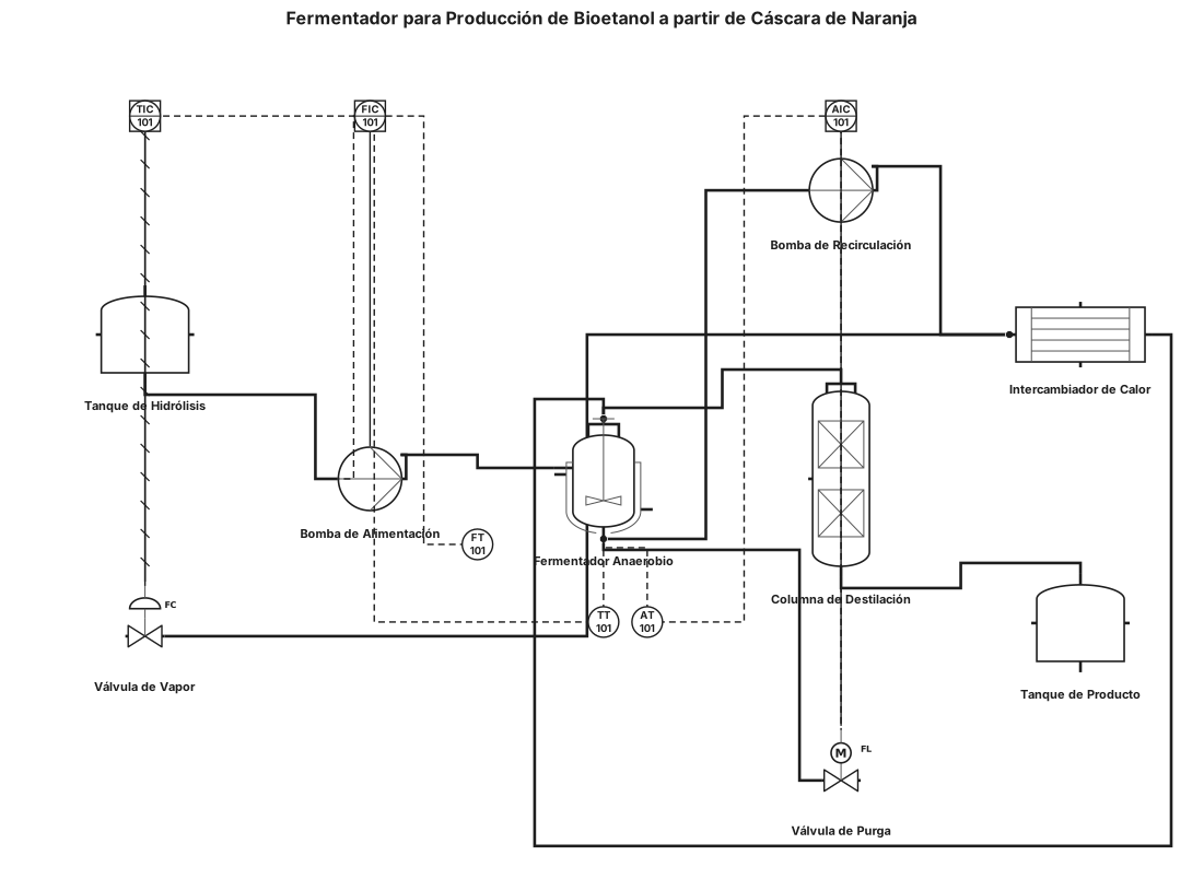
reactor fermentador para obtener bioetanol de cascara de naranja
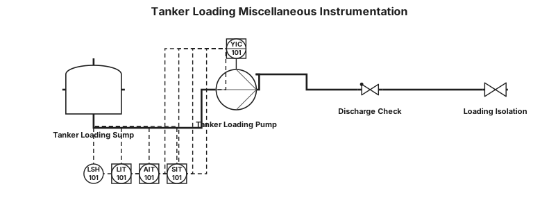
"5.9. Miscellaneous" Description Type Location Purpose Qty Tanker Loading Pump DOL Tanker Loading Bay Pump for Tanker Loading 1 Tanker Loading Sump Level High Switch Level Switch Tanker Loading Sump Tanker Loading Sump Level Protection 1 Tanker Loading Sump Level Ultrasonic Level Tanker Loading Sump Sump Level Measurement 1 Ammonia Monitor Ammonia Monitor Unknown Ammonia Monitoring 1 Suspended Solids Monitoring Suspended Solids Monitor Tanker Loading Sump Suspended Solids Monitoring 1
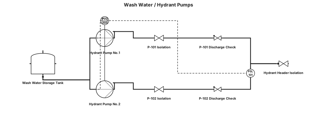
"5.8. Wash Water / Hydrant Pumps" Description Type Location Purpose Qty Hydrant Pump No.1 DOL Site Wash Water Supply Provide Wash Water to Site 1 Hydrant Pump No.2 DOL Site Wash Water Supply Provide Wash Water to Site 1 Hydrant Pump Pressure Switch - Low Pressure Switch Hydrant Pump Discharge Pipework Provide Low Pressure Feedback to PLC 1
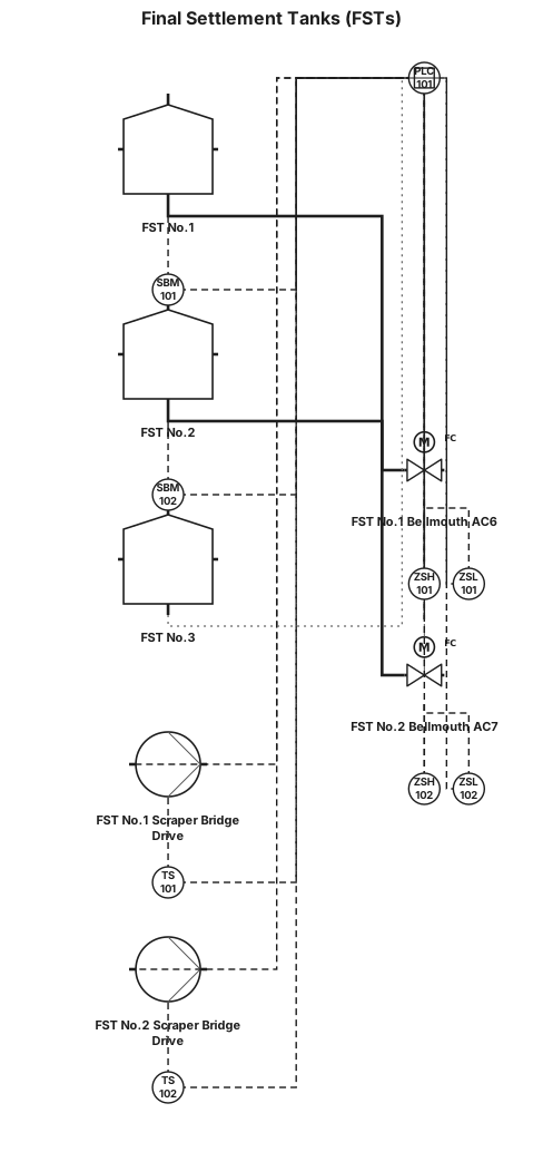
"5.7. Final Settlement Tanks (FSTs)" Description Type Location Purpose Qty FST No.1 Scraper Bridge Drive DOL FST No.1 Provide Sludge Collection for De-Sludge Purposes 1 FST No.1 Scraper Bridge Drive Torque Switch Torque Switch FST No.1 Provide Torque Protection for Drive 1 FST No.1 Bellmouth – AC6 Actuated Valve FST No.1 Sludge Outlet De-Sludging 1 FST No.1 Sludge Blanket Monitor Sludge Blanket Instrument FST No.1 Measure FST Sludge Level 1 FST No.1 Bellmouth Limits (Raised & Lowered) Limit Switch FST No.1 Sludge Outlet Provide Bellmouth Position Protection 2 FST No.2 Scraper Bridge Drive DOL FST No.2 Provide Sludge Collection for De-Sludge Purposes 1 FST No.2 Scraper Bridge Drive Torque Switch Torque Switch FST No.2 Provide Torque Protection for Drive 1 FST No.2 Bellmouth – AC7 Actuated Valve FST No.2 Sludge Outlet De-Sludging 1 FST No.2 Sludge Blanket Monitor Sludge Blanket Instrument FST No.2 Measure FST Sludge Level 1 FST No.2 Bellmouth Limits (Raised & Lowered) Limit Switch FST No.2 Sludge Outlet Provide Bellmouth Position Protection 2 FST No.3 Scraper Bridge Drive DOL Status FST No.3 Provide FST Status Monitoring to PLC 1
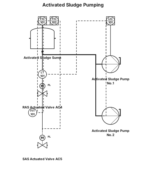
5.6.Activated Sludge Pumps Description Type Location Purpose Qty Activated Sludge Pump No.1 DOL Activated Sludge Sump Provide Sludge Flows for RAS/SAS 1 Activated Sludge Pump No.2 DOL Activated Sludge Sump Provide Sludge Flows for RAS/SAS 1 Activated Sludge Sump Level Ultrasonic Level Transmitter Activated Sludge Sump Provide Activated Sludge Sump Level 1 Activated Sludge Outlet Flow Magnetic Flow Meter Activated Sludge Pump Outlet Pipework Provide Activated Sludge Flow Measurement 1 RAS Actuated Valve – AC4 Actuated Valve Activated Sludge Pump Outlet Pipework Provides Route for RAS Flows 1 SAS Actuated Valve – AC5 Actuated Valve Activated Sludge Pump Outlet Pipework Provides Route for SAS Flows 1
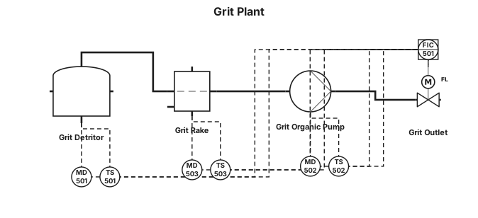
"5.4. Grit Plant" Description Type Location Purpose Qty Grit Detritor Drive DOL Grit Plant Grit Removal 1 Grit Organic Pump DOL Grit Plant Grit Removal 1 Grit Rake Drive DOL Grit Plant Grit Removal 1 Grit Detritor Drive Torque Switch Torque Switch Grit Plant Grit Plant Torque Protection 1 Grit Organic Pump Torque Switch Torque Switch Grit Plant Grit Plant Torque Protection 1 Grit Rake Drive Torque Switch Torque Switch Grit Plant Grit Plant Torque Protection 1
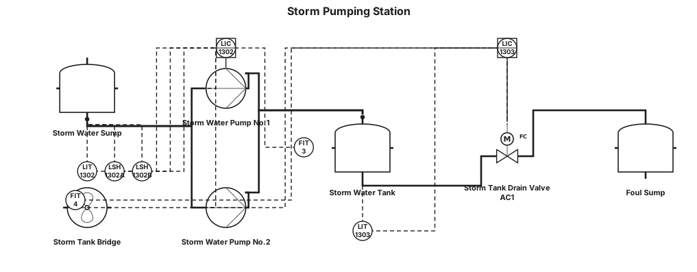
"5.3. Storm Pumping Station" Description Type Location Purpose Qty Storm Water Pump No.1 DOL Storm Water Sump Pump Overflow Foul Flows from Storm Water Sump to Storm Tank 1 Storm Water Pump No.2 DOL Storm Water Sump Pump Overflow Foul Flows from Storm Water Sump to Storm Tank 1 Storm Water Sump Level – LIT1302 Ultrasonic Level Transmitter Storm Water Sump Storm Water Sump Level Measurement 1 Storm Water Sump – Duty Start / Standby Start Ultrasonic Level Transmitter (Relay Outputs) Storm Water Sump Storm Water Sump Level Monitoring 2 Storm Water Pump Outlet Flow – FM3 Magnetic Flow Meter Outlet Pipework of Storm Water Sump Chamber Measures Outlet Flow of Storm Water Pumps 1 Storm Tank Level Ultrasonic Level Transmitter Storm Water Tank Storm Water Tank Level Measurement 1 Overflow from Storm Water Tank – FM4 Magnetic Flow Meter Overflow of Storm Water Tank Measures Overflow Flow of Storm Water Tank 1 Storm Tank Drain Valve – AC1 Actuated Valve Return Pipework of Storm Water Tank Provides Return Storm Flows to Foul Sump 1 Storm Tank Bridge DOL Storm Water Tank Tank Settlement to Centre 1
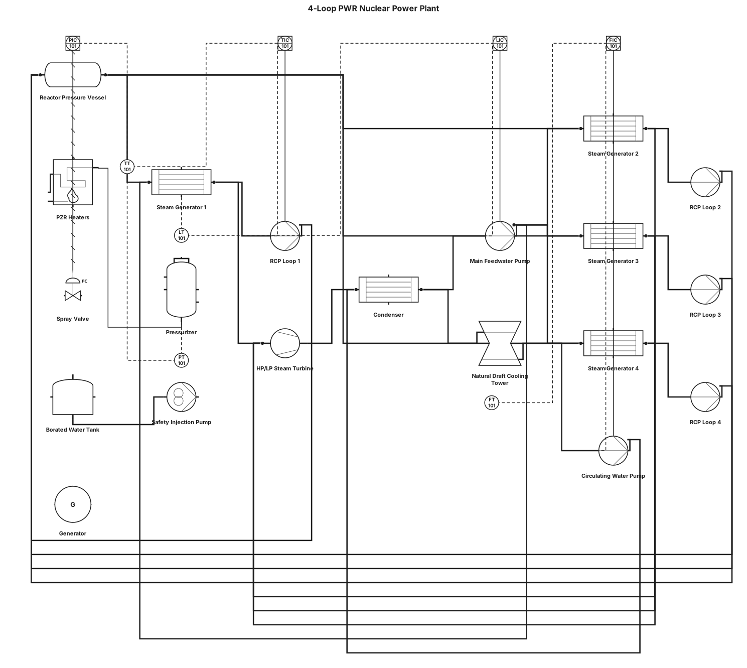
A 4-loop Pressurized Water Reactor (PWR) nuclear power plant process system consisting of three separate fluid circuits: 1. Primary Coolant Circuit (High Pressure, 155 bar, closed loop): - A central Reactor Pressure Vessel (RPV) containing the core. - Four identical parallel cooling loops. Each loop has a Hot Leg pipe leading from the RPV to the tube-side of a Steam Generator (SG), a Reactor Coolant Pump (RCP), and a Cold Leg pipe returning to the RPV. - A single Pressurizer (PZR) connected to one of the hot legs, equipped with electrical heaters at the bottom and a cold-water spray line with a control valve at the top for pressure control. - A 4-train Safety Injection System (ECCS) connected to the primary loops for emergency borated water injection. 2. Secondary Steam Circuit (Medium Pressure, 70 bar, closed loop): - The shell-side of the four Steam Generators where feedwater boils into steam. - Main steam lines from the top of the SGs combining to drive a High-Pressure and Low-Pressure Steam Turbine connected to an electrical generator. - A Condenser beneath the turbines to collect and condense exhaust steam. - A Main Feedwater Pump pumping the condensed water from the condenser back into the feedwater inlet at the bottom of the Steam Generators. 3. Tertiary Cooling Circuit (Open/Semi-closed loop): - A cooling water intake from a river/reservoir. - A Circulating Water Pump pushing cold water through the tube-side of the Condenser to condense the secondary steam. - Hot discharge lines leading from the condenser to a natural draft Cooling Tower for heat rejection before returning to the source.
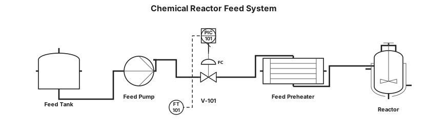
A P&ID for a chemical reactor feed system: feed tank, centrifugal pump, flow transmitter with a PID controller driving a control valve, and a heat exchanger before the reactor inlet
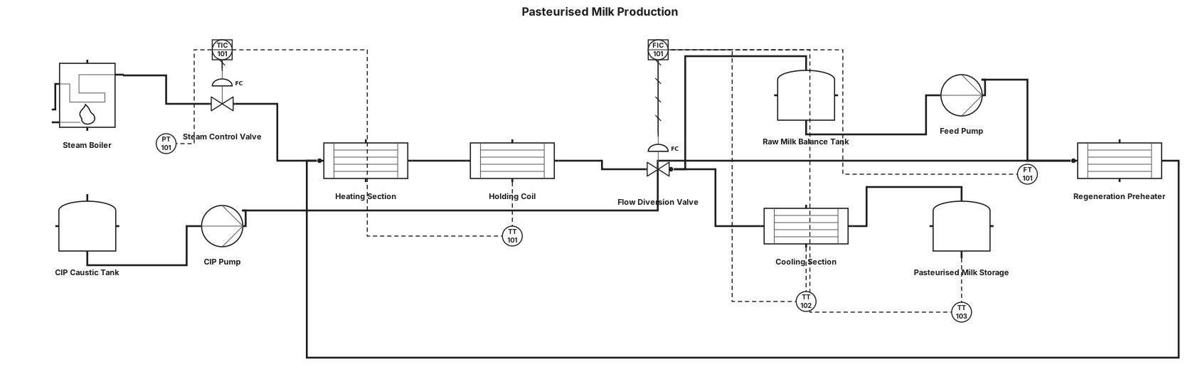
A P&ID for a chemical making pesterised milk.
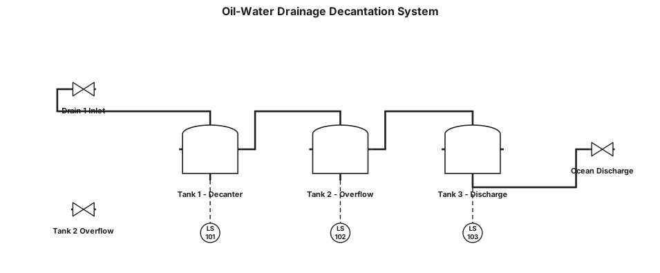
Residual oil and water through drain 1 enter tank 1. In tank 1 we have a decantation system where oil and cement residues will settle at the bottle. The water remain at the top and go to tank 2. When tank 2 overflows water go to tank 3. Then water from tank 3 go into the ocean. It is a drainage system
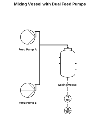
mixing vessel with two pumps to transfer liquid into the vessel, and temperature monitoring device
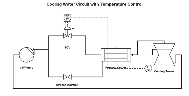
Cooling water circuit with temperature control valve and bypass
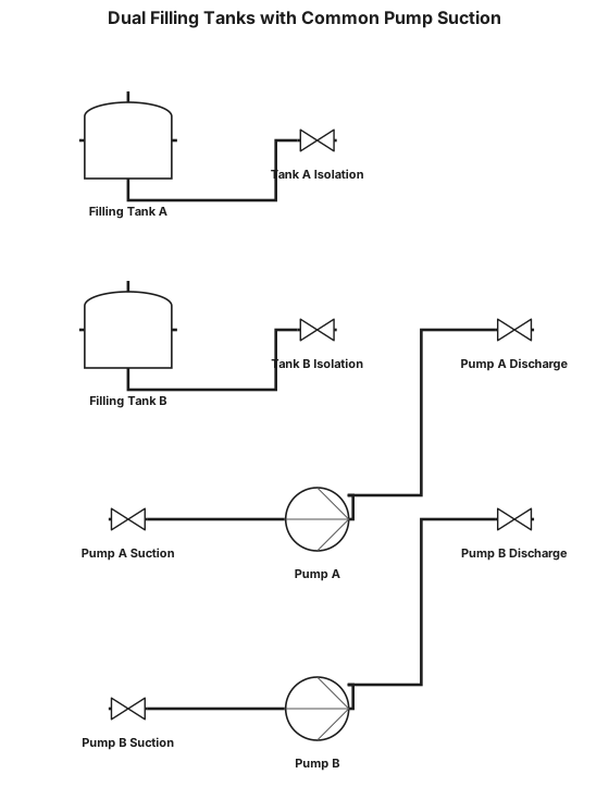
A P&ID for a two filling tanks connected to common header feeding into common suction for two centrifugal pumps which connect to a common line
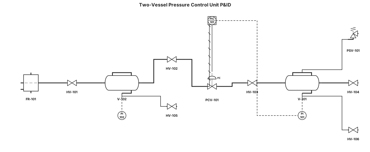
Create a professional P&ID (Piping and Instrumentation Diagram) for a two-vessel pressure control training unit based on the attached reference image. Use standard ISA/ISO P&ID symbols, black-and-white engineering drafting style, clean orthogonal piping, and clear equipment tags. Equipment and instrumentation to include: Two horizontal pressure vessels, one upper vessel tagged V-101 and one lower vessel tagged V-102. A pressure indicator/gauge on each vessel: PI-101 on V-101 and PI-102 on V-102. A pressure control/regulating valve in the connecting process line, tagged PCV-101. A pressure controller PIC-101 associated with the pressure-control loop, if automatic control is represented. An inlet air/gas line entering from the lower-left side. A filter/regulator assembly on the inlet line, tagged FR-101. Manual isolation valves on the inlet, vessel connections, and outlet. Bottom drain valves for both pressure vessels. A pressure relief/safety valve PSV-101 on the pressure vessel only if shown/confirmed by the reference equipment. Process piping connecting the two vessels and control components. Instrument signal lines should be dashed and process piping should be solid. Arrange the P&ID to resemble the physical layout in the reference image: upper pressure vessel above lower pressure vessel, pressure-control valve between/near the vessel connection, inlet equipment at lower left, pressure indicators mounted on the vessels, and process outlet on the right. Use standard ISA instrument bubbles and valve symbols. Do not draw the equipment as realistic red tanks; represent it as a conventional engineering P&ID. Include a legend for instrument abbreviations and a title: "Two-Vessel Pressure Control Unit P&ID". Do not add equipment that is not visible or reasonably implied by the reference image.
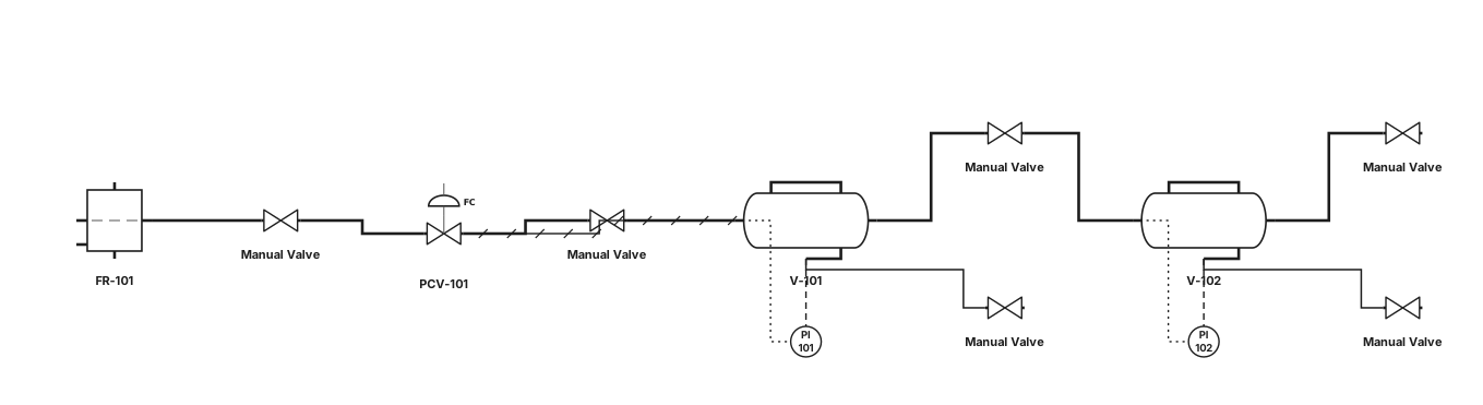
Create a standard ISA P&ID from the attached photograph of a two-vessel pressure control unit. Identify and represent only the visible process equipment: two horizontal pressure vessels, pressure gauges, inlet filter/regulator, manual valves, pressure regulating/control valve, process piping, and vessel drains. Use standard ISA symbols and tags V-101, V-102, PI-101, PI-102, FR-101 and PCV-101. Show the upper vessel above the lower vessel and reproduce the approximate physical piping arrangement shown in the photograph. Use solid process lines and dashed instrument signal lines. Do not invent flow connections, instruments, or safety valves that cannot be identified from the photograph. Produce a clean black-and-white engineering P&ID suitable for an academic report.
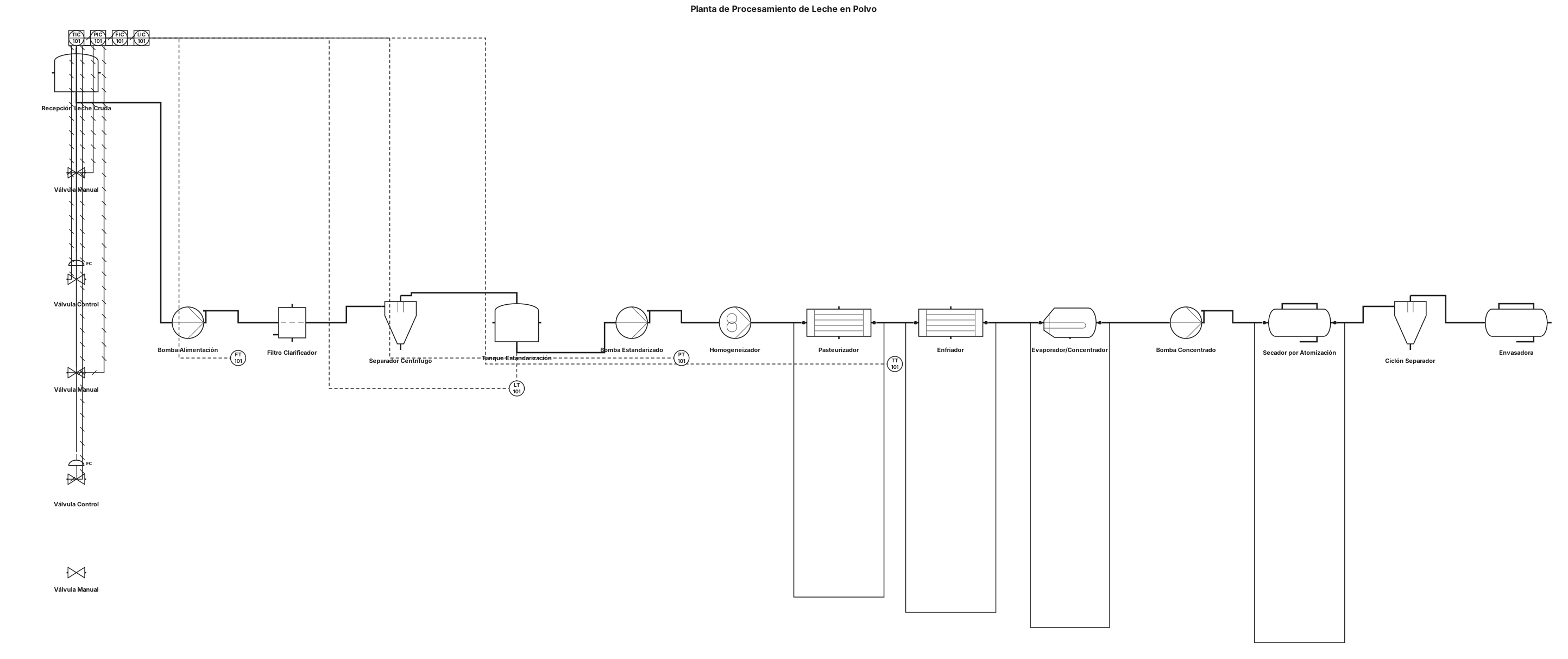
Recepción de leche cruda → Filtración y clarificación → Desnatado/separación centrífuga → Tanque de estandarización → Homogeneización → Pasteurización y enfriamiento → Concentración/evaporación → Secado por atomización → Ciclón separador → Envasado. Utiliza simbología estándar de DTI/P&ID para: * Tanques * Bombas * Filtros * Separador centrífugo * Homogeneizador * Intercambiador de calor * Evaporador/concentrador * Secador por atomización * Ciclón separador * Envasadora * Válvulas manuales y de control * Instrumentos de temperatura, presión, flujo y nivel Conecta los equipos mediante tuberías, colocando flechas que indiquen la dirección del flujo. Mantén las líneas de servicios (vapor, agua de enfriamiento y aire) separadas de la línea principal de leche. El diagrama debe ser limpio, horizontal, ordenado y fácil de leer, parecido a un DTI académico de Ingeniería Química. No hagas un diagrama de flujo con cuadros. No agregues equipos que no correspondan al proceso. No hagas circuitos cerrados ni tuberías que regresen innecesariamente a equipos anteriores.
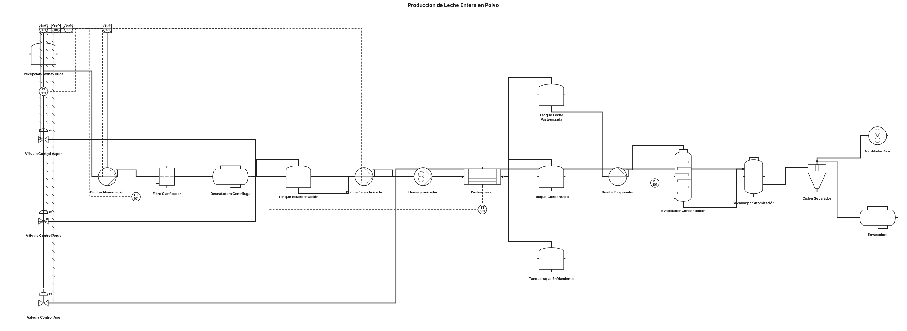
Crea un DTI/P&ID del proceso de producción de leche entera en polvo tomando como referencia la estructura y recorrido de proceso de la imagen proporcionada. Mantén una distribución horizontal y ordenada, con los equipos conectados mediante tuberías y flechas de dirección de flujo. El proceso debe seguir este orden: Recepción de leche cruda → filtración y clarificación → desnatado → estandarización → homogeneización → pasteurización y enfriamiento → concentración/evaporación → atomización/secado → envasado. No lo hagas como un diagrama de bloques simple. Utiliza simbología P&ID/DTI para representar cada equipo, incluyendo: * Tanques * Bombas * Filtros * Separador/desnatadora * Homogeneizador * Intercambiador de calor para pasteurización * Evaporador/concentrador * Secador por atomización * Ventilador * Ciclón o separador de polvo * Envasadora * Válvulas manuales y de control * Indicadores de temperatura, presión, flujo y nivel Agrega las líneas de proceso y de servicios, incluyendo leche, vapor, condensado, agua de enfriamiento, aire caliente y aire húmedo. Coloca flechas indicando el sentido del flujo. Identifica los equipos con etiquetas de ingeniería como T-101, P-101, F-101, E-101, EV-101, SD-101, etc. El resultado debe parecerse en distribución y recorrido a la imagen de referencia, pero debe ser un DTI/P&ID profesional con simbología de ingeniería, no un balance de materia. Ojo: no le pidas que copie los valores de G, SN, A, kg/h, etc. de esa imagen si tu maestra te pidió específicamente un DTI, porque esos son datos del balance de materia. El DTI debe enfocarse en equipos + tuberías + válvulas + instrumentos.
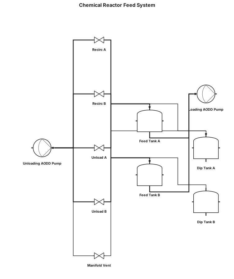
A P&ID for a chemical reactor feed system: feed tank*2,AODD pump*2 (loading and unloading), Have recirculation line from transfer line from unloading AODD pump to each tank and both have vent line connecting to a dip tank separately and the discharge of unloading AODD pump is fixed line to 2 no of difference tanks. There is a vent line in the unloading manifold has well.
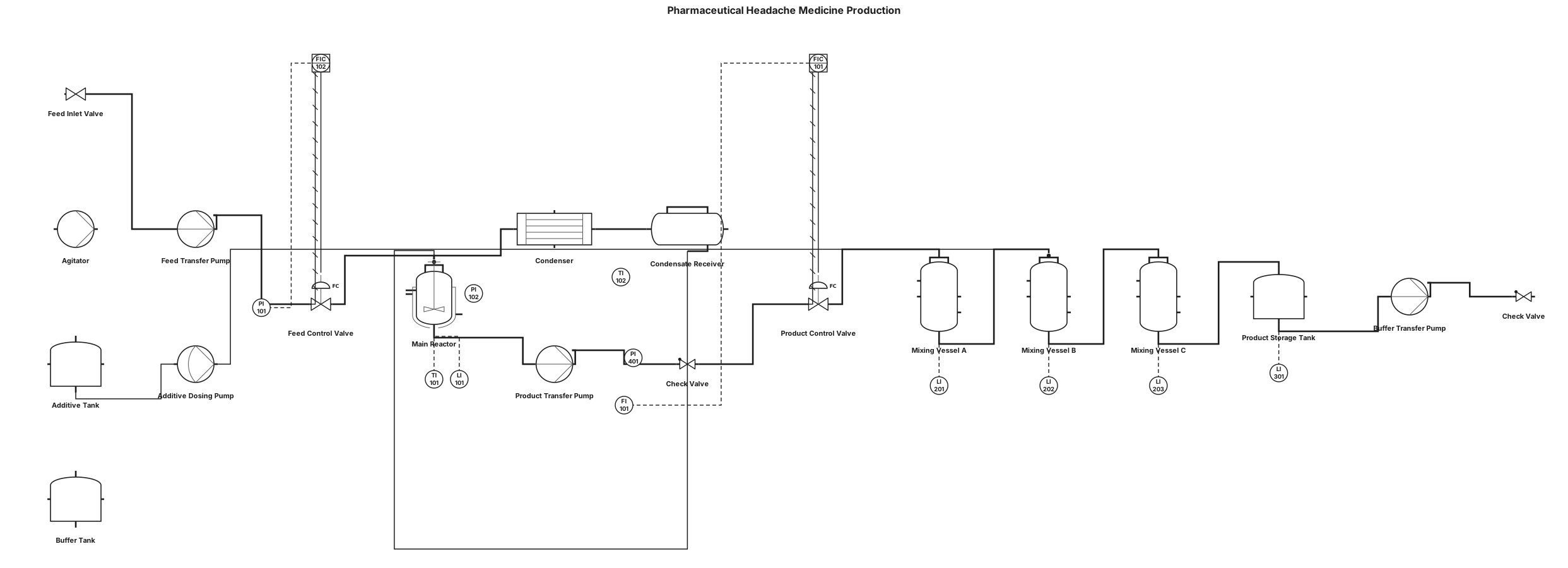
Create a detailed pharmaceutical manufacturing P&ID for a small-scale headache medicine production process. Use a professional engineering P&ID layout with ANSI/ISA-style symbols and equipment tags. Arrange the process generally from left to right. Main process: 1. Raw material feed enters from the left into a main vertical process vessel/reactor. 2. Connect the feed line through an inlet valve and transfer pump. 3. The main vessel has an agitator and level indication. 4. From the top of the main vessel, connect a vapor/product line to a horizontal heat exchanger or condenser. 5. Connect the condenser to a smaller downstream vessel and return/condensate line. 6. From the bottom outlet of the main vessel, use a pump and piping to transfer material to several downstream processing vessels. 7. Include several vertical mixing/storage vessels arranged horizontally along the bottom process line. 8. Include a larger vessel on the right side connected to the downstream process. 9. Add additional small tanks and transfer pumps on the far right. 10. Connect all equipment with process piping and clearly show the direction of flow. Include: - Tanks and vessels - Agitated reactor/mixing vessel - Centrifugal or transfer pumps - Heat exchanger/condenser - Process valves - Check valves where appropriate - Pressure indicators - Temperature indicators - Level indicators - Flow indicators/transmitters where appropriate - Control valves - Equipment identification tags such as R-101, T-101, P-101, E-101, V-101 - Clearly labeled inlet and outlet streams - Flow arrows - Instrument signal lines - Professional engineering spacing and alignment Make it look like a real pharmaceutical-process P&ID rather than a simple flowchart. Use a clean black-and-white technical drawing style and keep equipment labels readable.
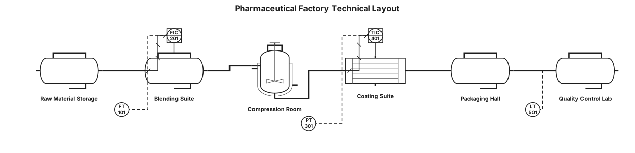
"Redraw this as a clean 2D pharmaceutical factory technical layout. Preserve the same room arrangement, equipment positions, walls, doors, labels, dimensions, and line connections. Use a professional black-and-white CAD drafting style. Make the output editable."