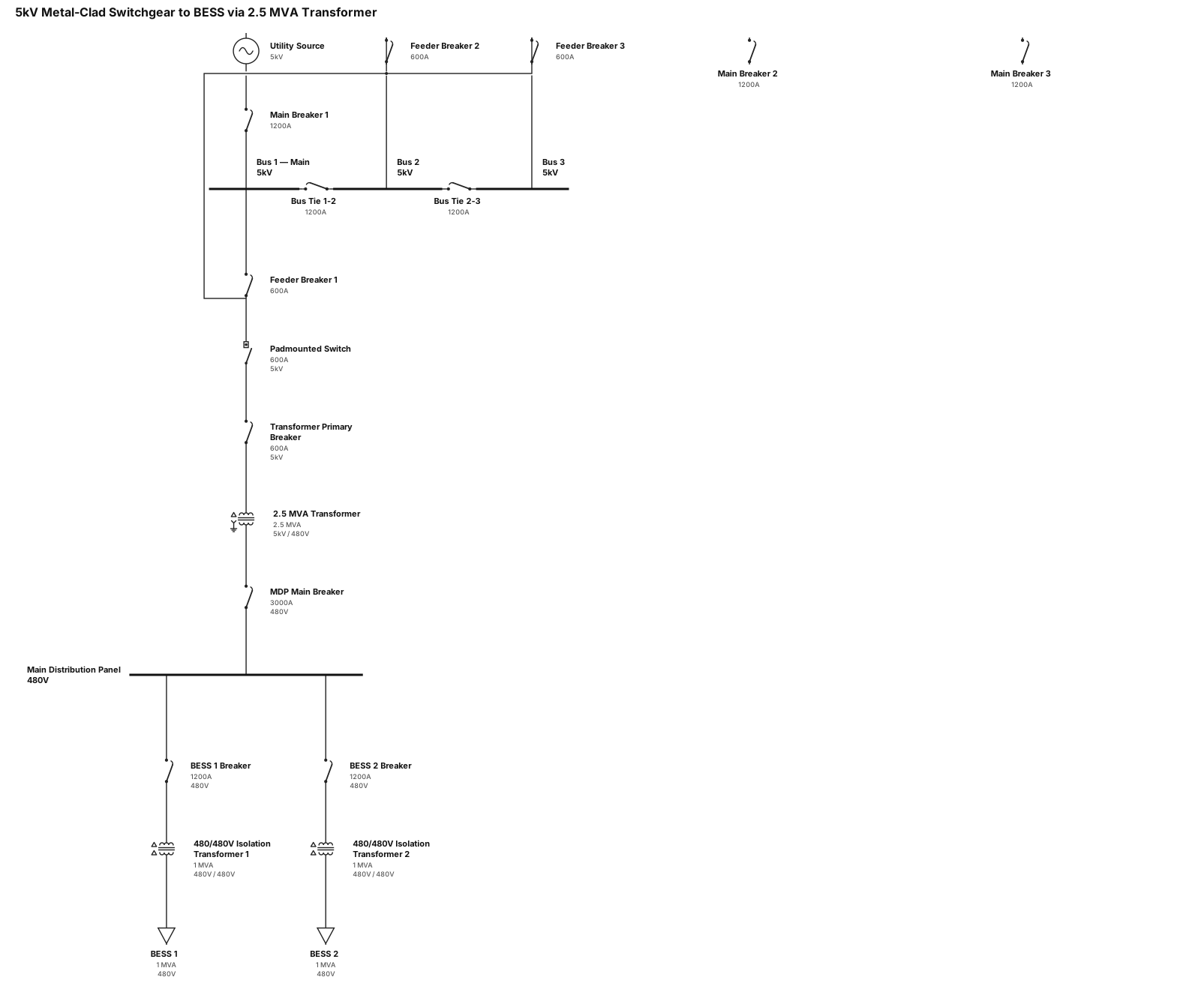
5kv metal clad switchgear (3 busses, mains and feeder breakers) feeding a padmounted switch feeding a 2.5mVA transformer via circuit breaker, transfomer steps down to 480V and feeds main distribution panel. Main distribution panel feeds two battery energy storage systems coupled via 480/480 transformers
NODE ARCHIVE · REAL DIAGRAM BRIEFS
Diagram Examples from Real Visitor Prompts
Browse eligible diagrams shared by FreeDiagram visitors, inspect the exact prompts, and build your own version.
Browse 3261 real creationsCOMMUNITY OUTPUTS · EXACT PROMPTS
Single Line Diagrams
Showing 49–72 of 196. No stock examples or system defaults. Choose a tool, study a real result, then reopen its prompt as your starting point.
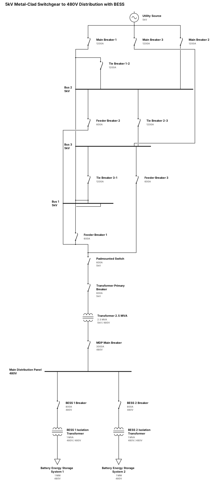
5kv metal clad switchgear (3 busses, 3 ties, mains and feeder breakers) feeding a padmounted switch feeding a 2.5mVA transformer via circuit breaker, transfomer steps down to 480V and feeds main distribution panel. Main distribution panel feeds two battery energy storage systems coupled via 480/480 transformers
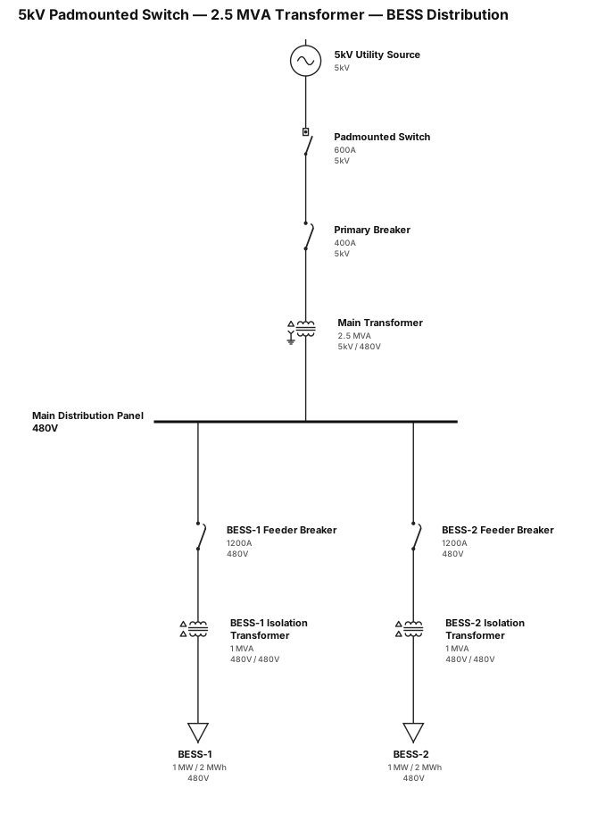
5kv padmounted switch feeding a 2.5mVA transformer via circuit breaker, transfomer steps down to 480V and feeds main distribution panel. Main distribution panel feeds two battery energy storage systems coupled via 480/480 transformers
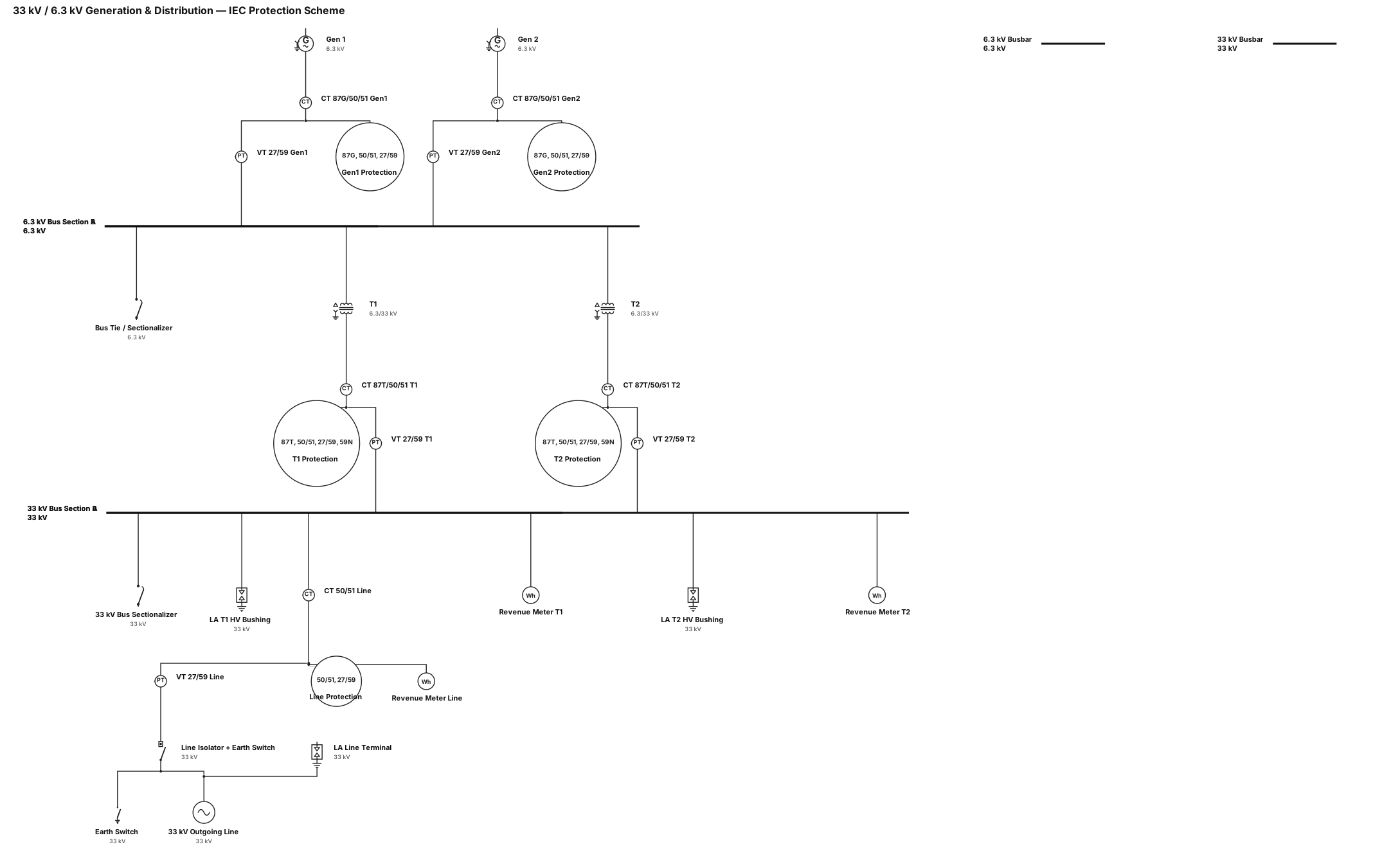
Standardize Symbols: Replace all circuit breaker representations with standard IEC rectangular CB symbols, and clearly distinguish off-load isolators and earth switches. Add Protection & Measurement Scheme: Insert CTs and VTs across the 6.3 kV generator tails, 33 kV transformer bays, and the outgoing 33 kV line for protection relays (ANSI 87G, 87T, 50/51, 27/59, 59N) and utility-grade Revenue Tariff Meters. Remove Redundant Devices: Eliminate one of the series isolators on the 33 kV outgoing line, and add an integral Earth Switch to the remaining line isolator. Incorporate Bus Sectionalizing: Introduce a Bus Tie / Sectionalizer breaker on the 6.3 kV or 33 kV busbar to allow independent operation of Gen 1 / T1 while servicing Gen 2 / T2. Add Surge Protection: Position 33 kV Lightning Arresters (LA) at the line terminal termination point and near the 33 kV transformer high-voltage bushings.
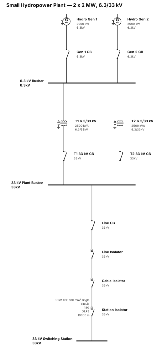
A single-line diagram for a small hydropower plant, consist of 2 x 2000kw generator @ 6.3kv each into 2 step up transformers 6.3/33kv to the 33kv switching station via 10km 33kv 180mm2 ABC single circuit via switchgear
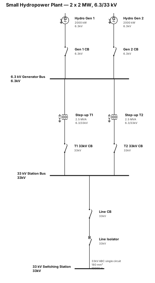
A single-line diagram for a small hydropower plant, consist of 2 x 2000kw generator @ 6.3kv each into 2 step up transformers 6.3/33kv to the 33kv switching station via 10km 33kv 180mm2 ABC single circuit
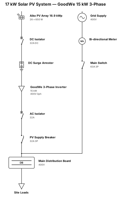
A single-line diagram for a 17kw solar system with goodwe 3 phase 15kw inverter, 26x 650watt aiko solar panels
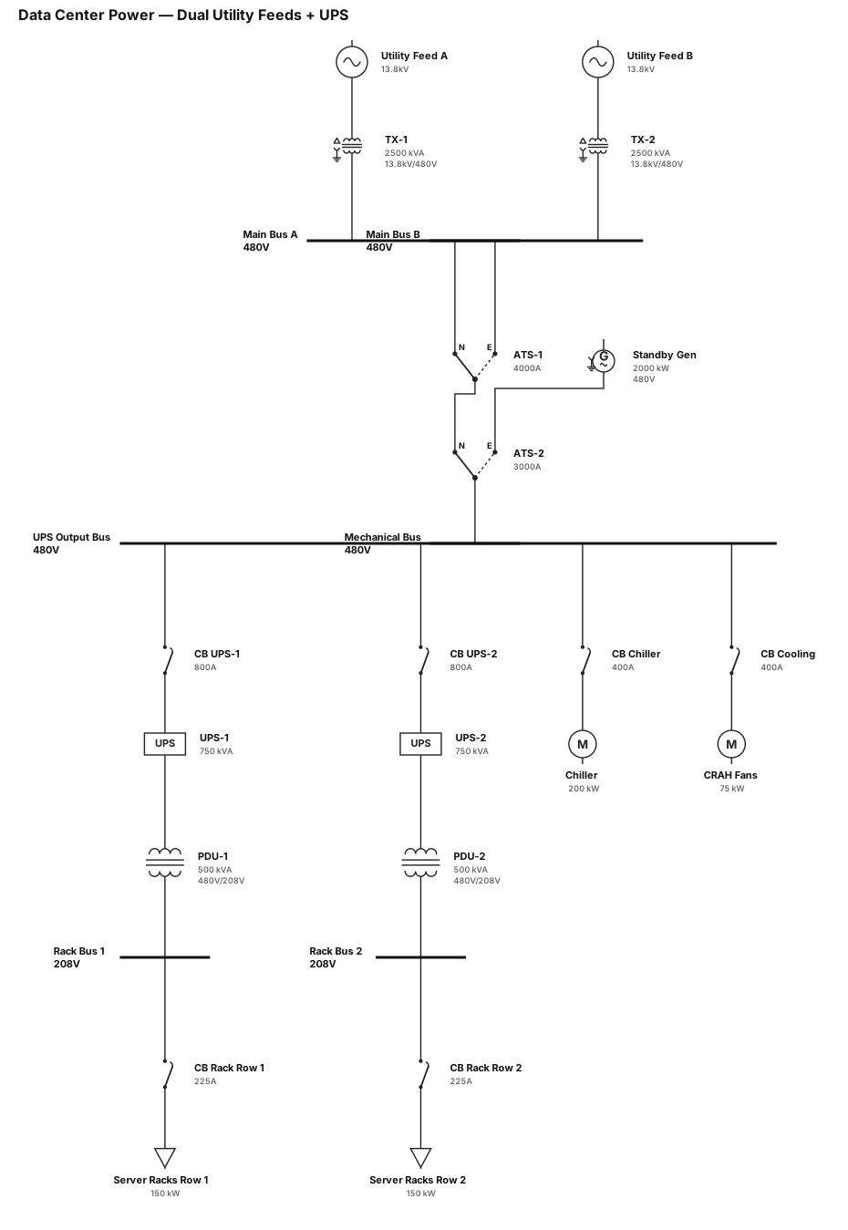
Data center power system with UPS and dual utility feeds

Panel FunctionMain ProtectionFeeder Cable SpecificationGrounding CableEMPMain Energy Meter Panel630A MCCB (4P) $3\times 300 + 150\text{ mm}^2\text{ Cu/XLPE/PVC}$ $70\text{ mm}^2\text{ Cu/PVC}$ MDBMain Distribution Board630A Busbars / MCCB $3\times 300 + 150\text{ mm}^2\text{ Cu/XLPE/PVC}$ $70\text{ mm}^2\text{ Cu/PVC}$ LDP-01LG Lighting Panel20A MCB / MCCB $4\times 6\text{ mm}^2\text{ Cu/XLPE/PVC}$ $6\text{ mm}^2\text{ Cu/PVC}$ PDP-02LG Power Panel100A MCCB $4\times 35\text{ mm}^2\text{ Cu/XLPE/PVC}$ $16\text{ mm}^2\text{ Cu/PVC}$ HVP-03LG HVAC Panel80A MCCB $4\times 25\text{ mm}^2\text{ Cu/XLPE/PVC}$ $16\text{ mm}^2\text{ Cu/PVC}$ LDP-11UG Lighting Panel20A MCB / MCCB $4\times 6\text{ mm}^2\text{ Cu/XLPE/PVC}$ $6\text{ mm}^2\text{ Cu/PVC}$ PDP-12UG Power Panel100A MCCB $4\times 35\text{ mm}^2\text{ Cu/XLPE/PVC}$ $16\text{ mm}^2\text{ Cu/PVC}$ HVP-13UG HVAC Panel80A MCCB[cite: 1]$4\times 25\text{ mm}^2\text{ Cu/XLPE/PVC}$ $16\text{ mm}^2\text{ Cu/PVC}$ LDP-21Mezzanine Lighting20A MCB / MCCB[cite: 1]$4\times 6\text{ mm}^2\text{ Cu/XLPE/PVC}$ $6\text{ mm}^2\text{ Cu/PVC}$ PDP-22Mezzanine Power100A MCCB[cite: 1]$4\times 35\text{ mm}^2\text{ Cu/XLPE/PVC}$ $16\text{ mm}^2\text{ Cu/PVC}$ HVP-23Mezzanine HVAC80A MCCB[cite: 1]$4\times 25\text{ mm}^2\text{ Cu/XLPE/PVC}$ $16\text{ mm}^2\text{ Cu/PVC}$ HVP-R3Outdoor HVAC (IP65)80A MCCB[cite: 1]$4\times 25\text{ mm}^2\text{ Cu/XLPE/PVC}$ $16\text{ mm}^2\text{ Cu/PVC}$ UDP-05IT Room HVAC Panel80A MCCB[cite: 1]$4\times 25\text{ mm}^2\text{ Cu/XLPE/PVC}$[cite: 2]$16\text{ mm}^2\text{ Cu/PVC}$[cite: 2]
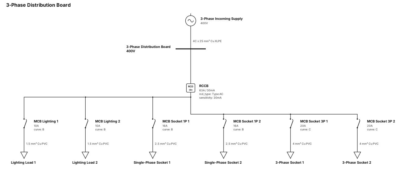
3 phase incoming supply cable, 3 phase distribution board, no energy meter, rccb, lighting load, lighting load, single phase socket, single phase socket, 3 phase socket, 3 phase socket
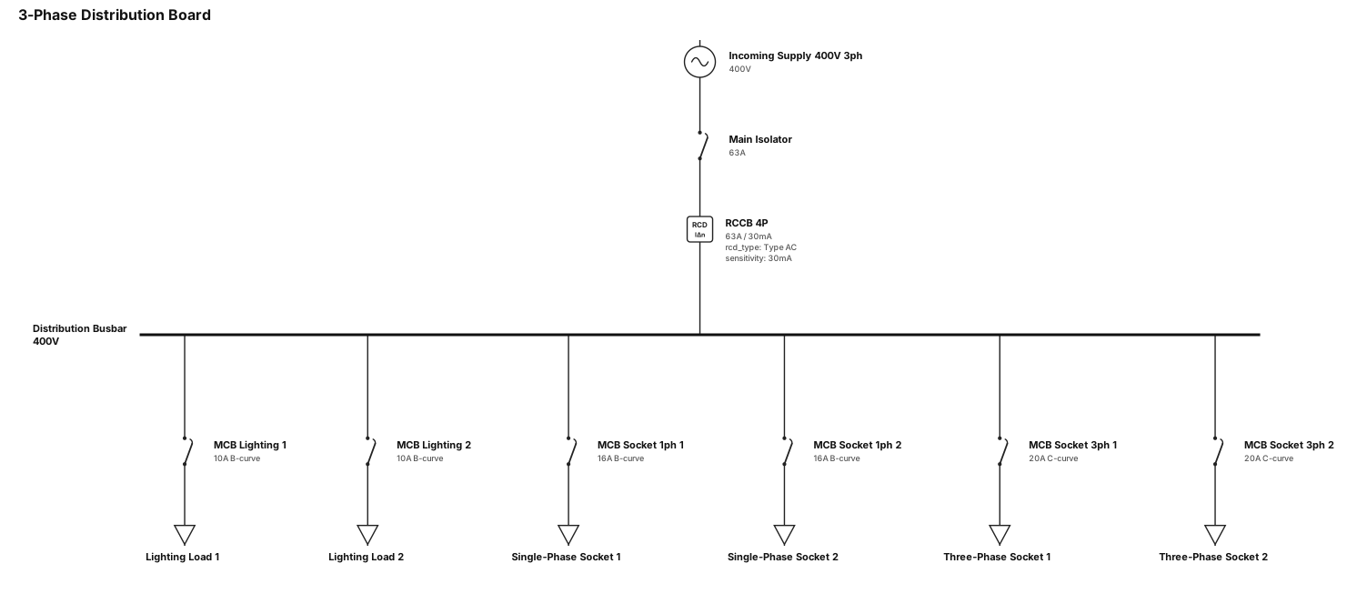
3 phase distribution board, no energy meter, rccb, lighting load, lighting load, single phase socket, single phase socket, 3 phase socket, 3 phase socket
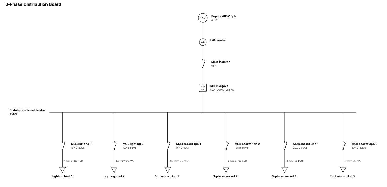
3 phase distribution board, rccb, lighting load, lighting load, single phase socket, single phase socket, 3 phase socket, 3 phase socket
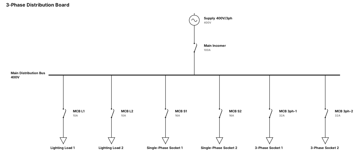
3 phase distribution board; lighting load, lighting load, single phase socket, single phase socket, 3 phase socket, 3 phase socket
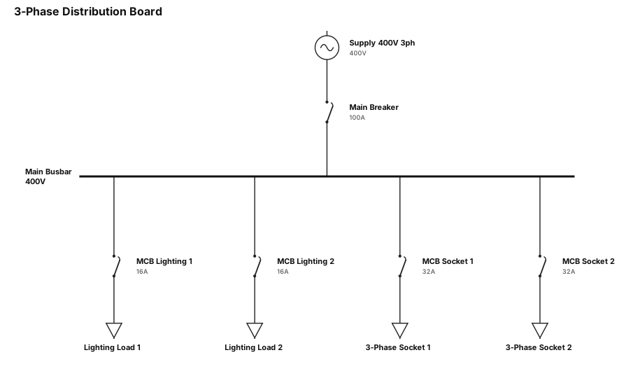
3 phase distribution board; lighting load, lighting load, 3 phase socket, 3 phase socket,
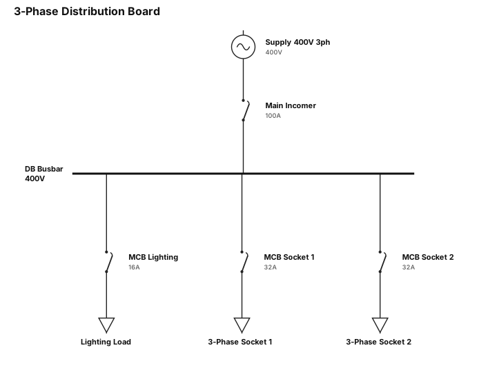
3 phase distribution board; lighting load, 3 phase socket, 3 phase socket
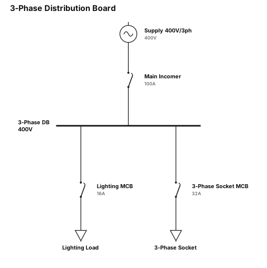
3 phase distribution board; lighting load, 3 phase socket
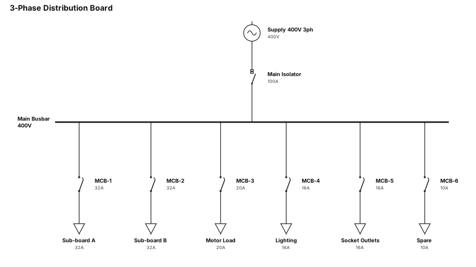
A single-line diagram for a 3 phase distribution board, without no 3-phase kWh meter
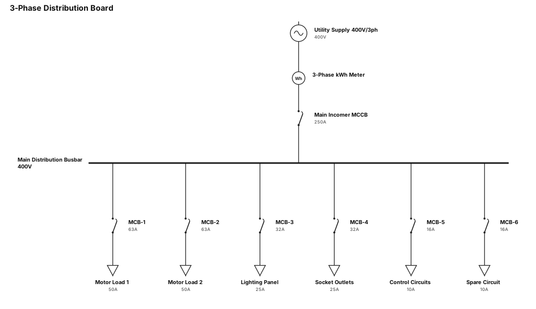
A single-line diagram for a 3 phase distribution board
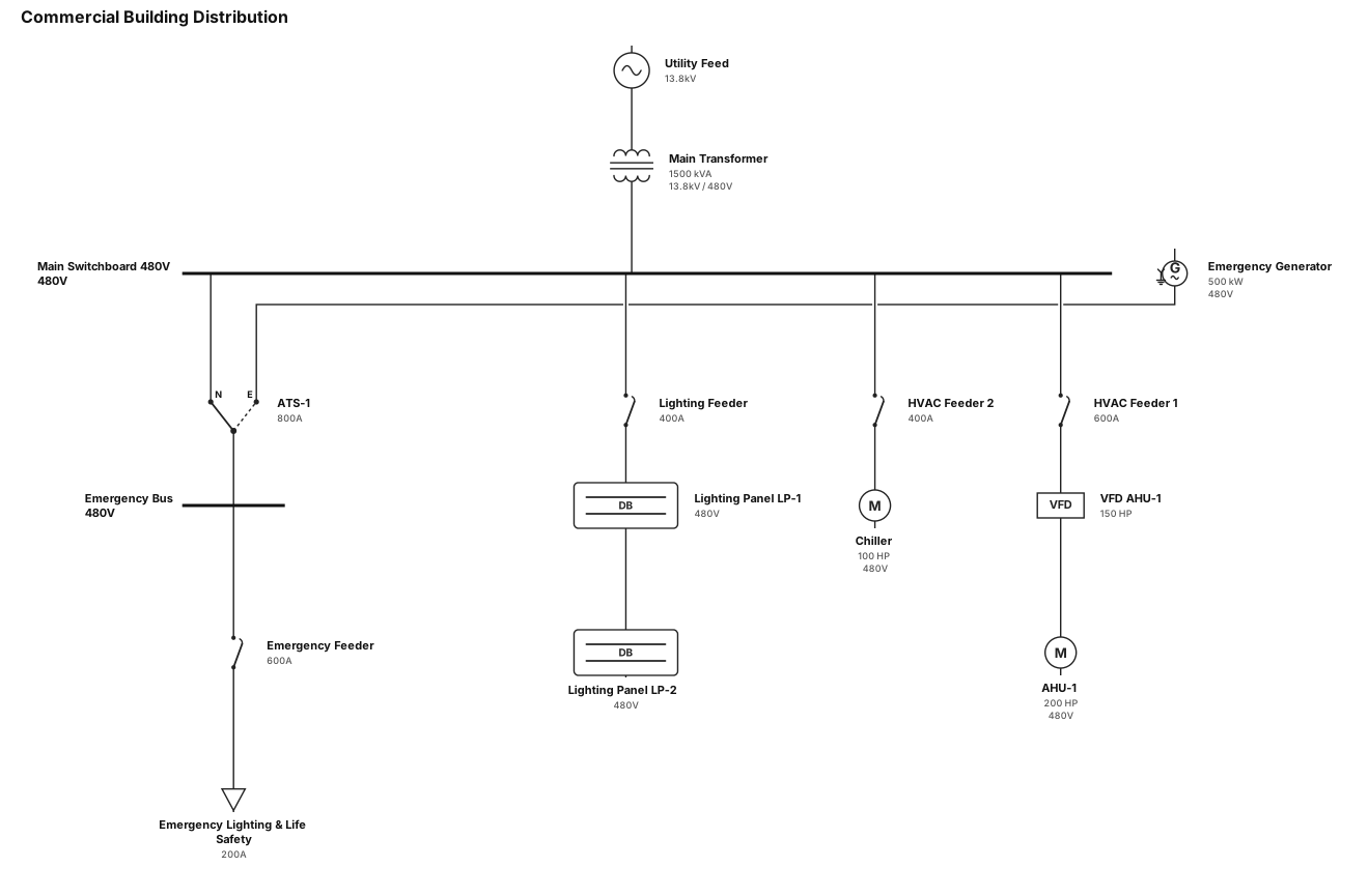
A single-line diagram for a commercial building: utility feed through a main transformer to a 480V switchboard, then to lighting panels, HVAC equipment, and an emergency generator with ATS
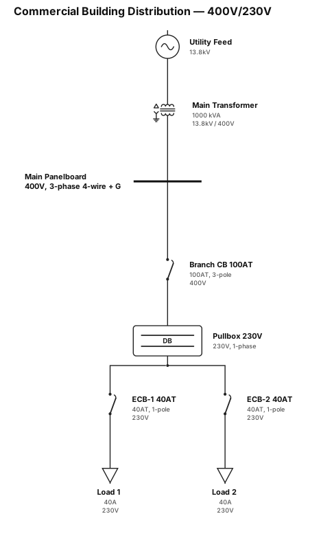
A single-line diagram for a commercial building: utility feed through a main transformer to a 400VAC, 4 wire with grounding panelboard, then in its branch wich is 100at 3phase 400vac cb going to a single pase 230vac pullbox, then to 2 ecb with 40at cb, 230vac 1 phase
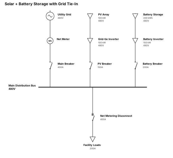
Solar plus battery storage and grid tie-in with inverter and net metering disconnect
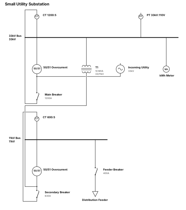
Small utility substation with protection relays and metering
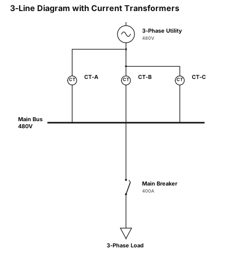
draw a 3-line diagram with a current transformer around each line
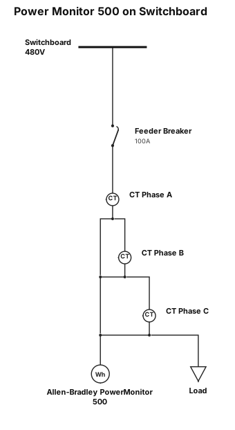
Draw a box that houses a Allen-Bradley Power Montior 500 that connects to a typical switchboard with a CT on each phase