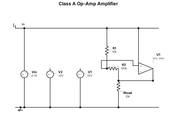
Clas A op amp circuit
NODE ARCHIVE · REAL DIAGRAM BRIEFS
Diagram Examples from Real Visitor Prompts
Browse eligible diagrams shared by FreeDiagram visitors, inspect the exact prompts, and build your own version.
Browse 3279 real creationsCOMMUNITY OUTPUTS · EXACT PROMPTS
All visitor creations
Showing 817–840 of 3279. No stock examples or system defaults. Choose a tool, study a real result, then reopen its prompt as your starting point.
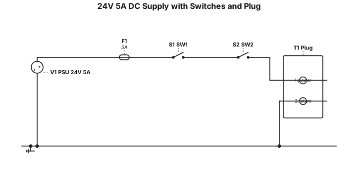
A 24V, 5A DC power supply connecting to two switches and then to a plug

Part 1: Food Dye Selection and Pasco Spectrophotometer Use Choose two food dye stock solutions (M1=2.510-4M) from the available choices (Red #40, Green #3, Yellow #5, Yellow #6, or Blue #1. Fill cuvette 34 full with stock solution; record visible absorption spectrum using Pasco spectrometer. Identify peak wavelength () for each dye and fix this wavelength for all subsequent readings. Part 2: Preparation of Standard Solutions Use the dilution equation M1V1=M2V2 to calculate the volume of stock solution (V1) needed to prepare five standard solutions (A–E) in a total volume V2=25.0mL within the specified concentration range. Pipette calculated V1 into a 25.0mL volumetric flask, dilute to mark with D.I. water, invert to mix, and transfer to labeled test tubes A–E. Thoroughly rinse glassware with D.I. water between samples and repeat for standards A–E and the second dye. Part 3: Measurement of the Absorbance of Each Dilution Set spectrometer to the dye's specific . Fill a cuvette 34 full with standard solution A, place it into the spectrometer, and click “Record”. Record the absorbance value in Data Table 2. Pour the solution from the cuvette back into test tube A. Repeat the absorbance measurement two additional times for a total of three trials per dilution. Rinse the cuvette with D.I. water and tap it dry gently on a paper towel. Repeat the process for standard solutions B through E and for the second food dye. Calculate the average absorbance for each sample and log the results in Data Tables 1–4 Part 4: Create Calibration Curves In Excel, plot Average Absorbance (Y-axis) vs. Final Concentration M2 (X-axis) as a Scatter Plot. Add a linear trendline, displaying equation (y=mx+b) and R2 value (0.95). Add title and axis labels. Repeat Steps 1–6 using the data from Table 3.
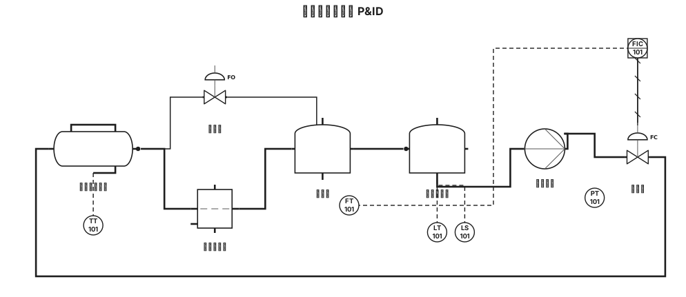
工具機 切削系統 p&id
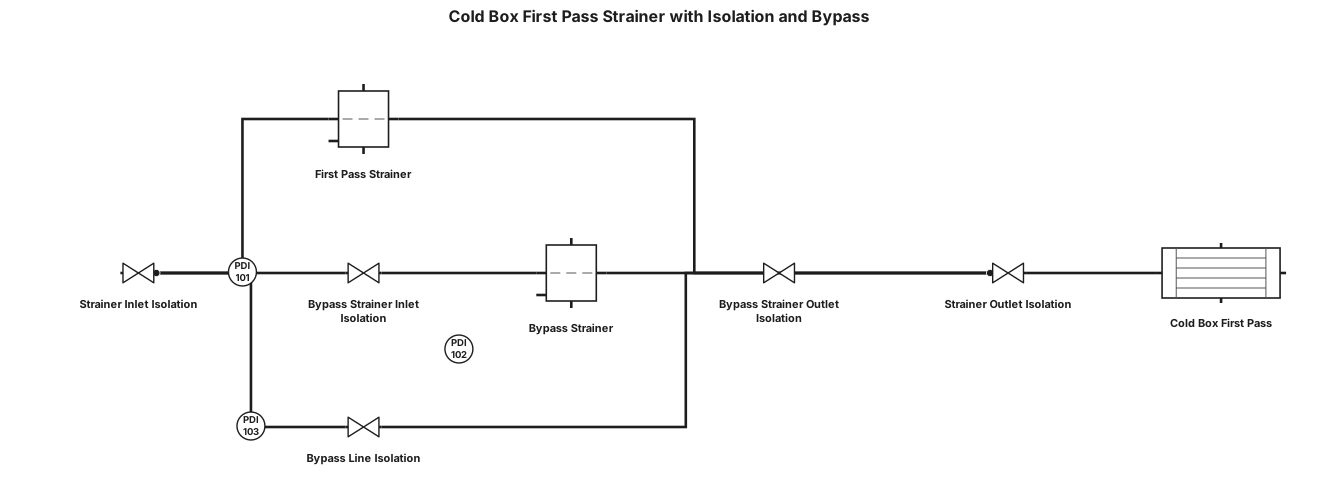
there is cold box its first pass gas inlet have a staainer and i want to make isolation for the stainer and also make a bypass also stainer on bypass

making an app for ai to track what is in fridge and provide recipes and keep track of expiration dates make lofi framework for: Checking the food inventory Page 1: Home Page Page 2: Inventory List For each item: expiry, detail, Sort options Sort by expiry, alphabetical, category, etc. Filter by inventory category filter (pantry, freezer) Filter by item category (dairy, protein, etc.) Search bar [F07] Add Item [F01] Add by writing down each item Add by taking a photo Mark Item as consumed Calendar Toggle (calendar view that shows which items are inspiring on what day) [Need to add new FR] Page 3: Add Item Page 4: View Item
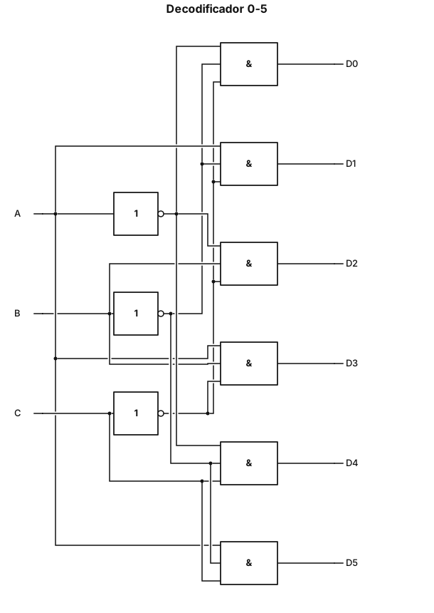
Generame un decodificador del 0 al 5 con compuertas lógicas
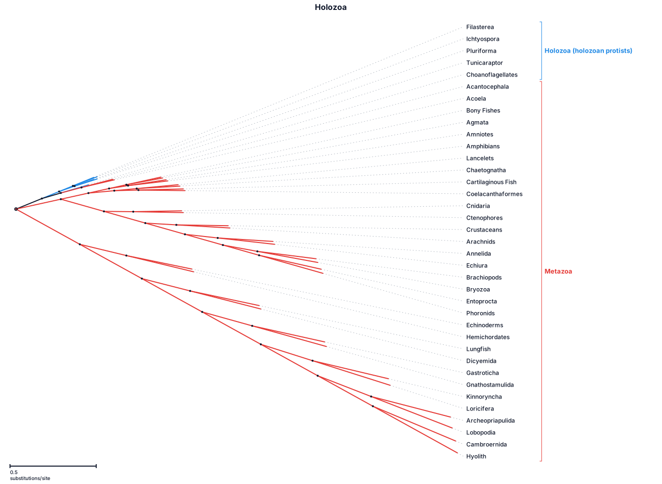
A phylogenetic tree of theclade Holozoa: Filasterea, Ichtyospora, Pluriforma, Tunicaraptor, Choanoflagellates Acantocephala, Acoela, Bony Fishes, Agmata, Amniotes, Amphibians, Annelida, Arachnids, Archeopriapulida, Brachiopods, Bryozoa, Cambroernida, Lancelets, Chaetognatha, Cartilaginous Fish, Cnidaria, Coelacanthaformes, Crustaceans, Ctenophores, Lungfish, Dicyemida, Echinoderms, Echiura, Entoprocta, Phoronids, Gastroticha, Gnathostamulida, Hemichordates, Hyolith, Lampreys, Kinnoryncha, Lobopodia, and Loricifera
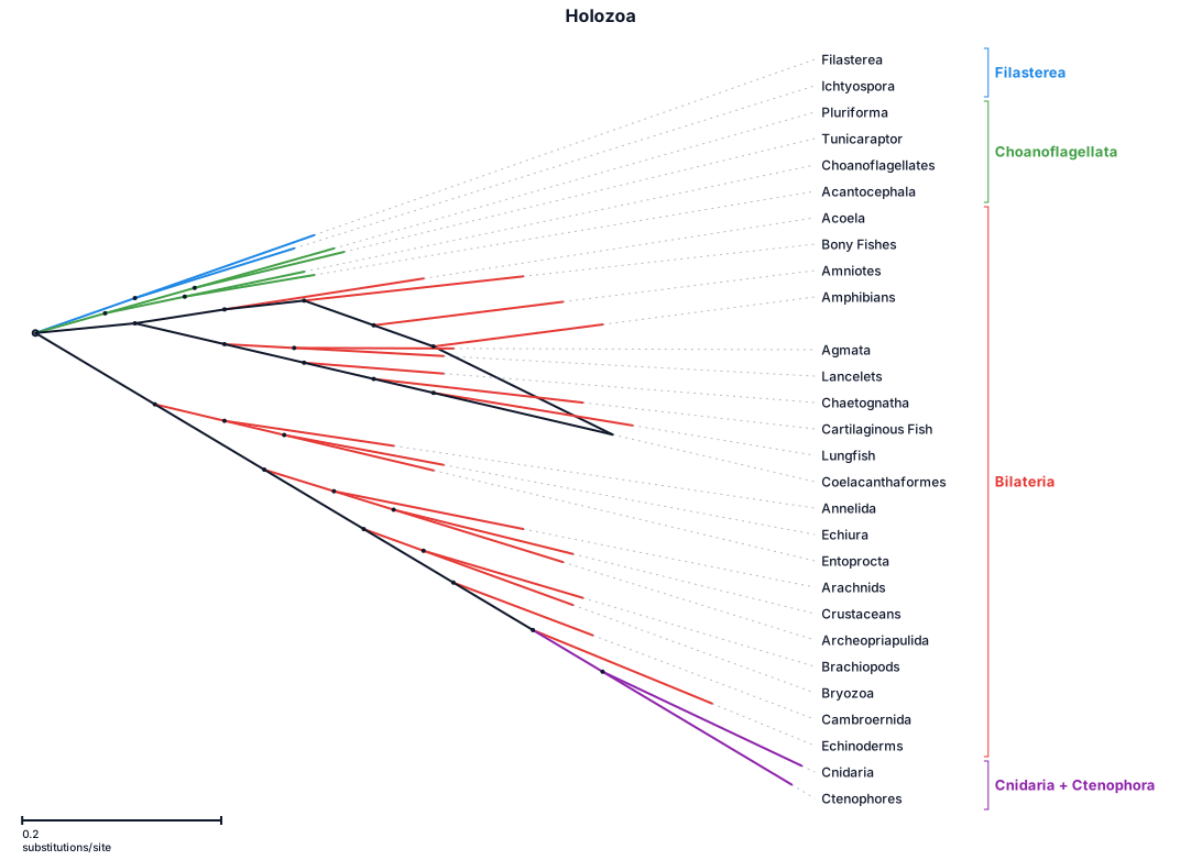
A phylogenetic tree of theclade Holozoa: Filasterea, Ichtyospora, Pluriforma, Tunicaraptor, Choanoflagellates Acantocephala, Acoela, Bony Fishes, Agmata, Amniotes, Amphibians, Annelida, Arachnids, Archeopriapulida, Brachiopods, Bryozoa, Cambroernida, Lancelets, Chaetognatha, Cartilaginous Fish, Cnidaria, Coelacanthaformes, Crustaceans, Ctenophores, Lungfish, Dicyemida, Echinoderms, Echiura, and Entoprocta with branch lengths
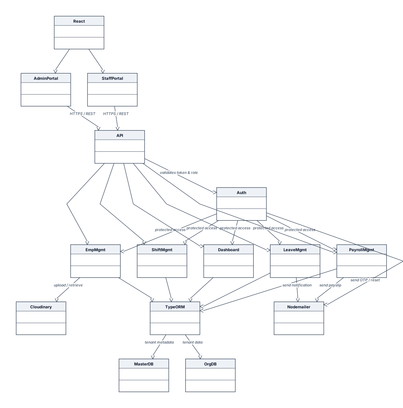
Create a professional **Software Component Diagram for a Human Resource Management System (HRMS)** for a B.Tech Information Technology project report. **Design requirements:** - White background with black text. - Thin purple borders and arrows. - Clean, simple, academic style. - Use standard UML component diagram notation. - Arrange components from top to bottom or left to right. - Keep labels readable and avoid unnecessary details. **Include these components and connections:** 1. **Frontend Layer** - React.js - Admin Portal - Staff Portal 2. **Backend Layer** - Node.js - Express.js REST API - Authentication and Authorization (JWT and Role-Based Access Control) - Employee Management - Shift and Attendance Management - Leave Management - Payroll Management - Dashboard and Reports 3. **Database Layer** - Master PostgreSQL Database - Organization-Specific PostgreSQL Databases - TypeORM for database communication 4. **External Services** - Cloudinary for file and image storage - Nodemailer for email notifications **Show the connections clearly:** - Admin Portal and Staff Portal communicate with the Express.js REST API. - The API connects to the backend HRMS modules. - Authentication and authorization control access to protected modules. - TypeORM connects the backend to the master database and organization-specific databases. - Cloudinary handles file uploads and storage. - Nodemailer sends email notifications. Use arrows to show communication and dependencies. Keep the master database visually separate from organization-specific databases to represent the multi-tenant architecture. The final diagram should be suitable for inserting into a project report as **Figure 6.6: Software Component Diagram**. Do not add unsupported technologies or unnecessary components.
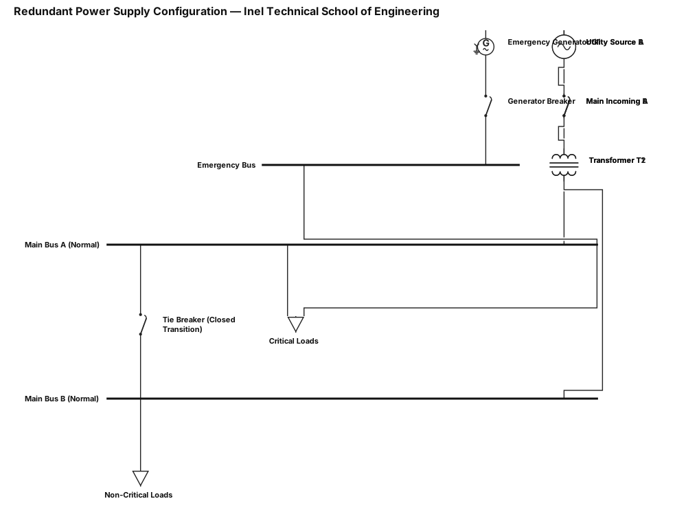
2.1. The system configuration must be redundant; this means there will be two independent power sources and a generator, operating under different conditions: * Normal operation: both main sources are operating * Critical operation: one transformer is lost, and the other takes on the entire load Inel – Technical School of Engineering Final Project | Power Quality Instructor: Daniel Sanchez * Emergency operation: the generator takes on the load via closed transition 2.2. Based on what was covered in class, present a configuration using a single-line diagram that includes all the minimum required elements discussed in class.
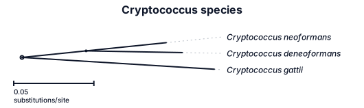
A phylogenetic tree of Cryptococcus neoformans, Cryptococcus deneoformans, and Cryptococcus gattii. Drawn with straight branches and 90 degree branch joins
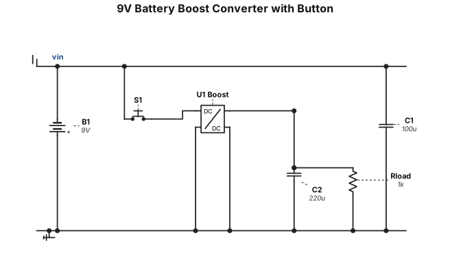
9 vlot battary going into a boost converter with a button
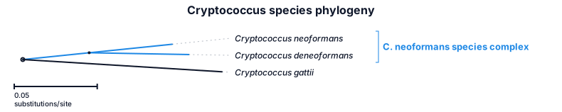
A phylogenetic tree of Cryptococcus neoformans, Cryptococcus deneoformans, and Cryptococcus gattii
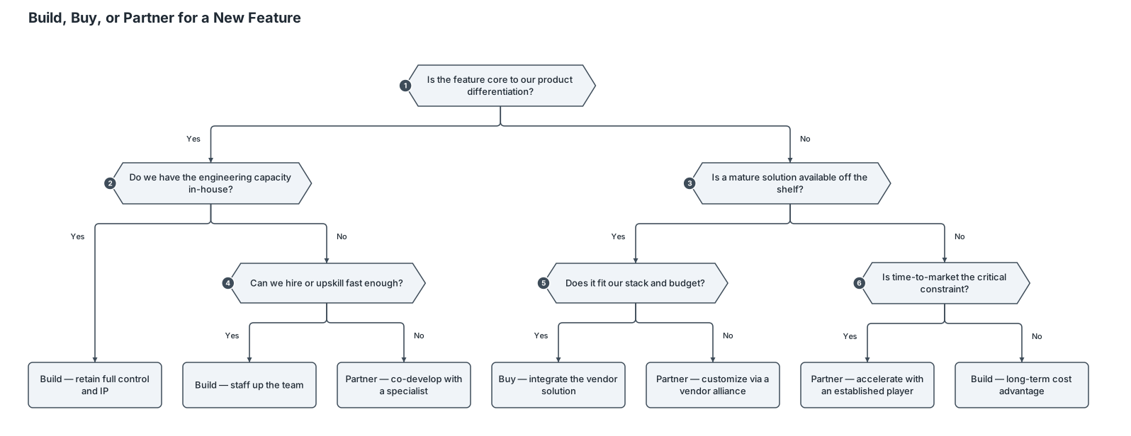
A decision tree for whether a startup should build, buy, or partner for a new feature1. Diagrama de jerarquía CONSTRUCCIÓN DE CASA DE 1 PISO (Resp: Ing. Residente) 1.1 CIMENTACIÓN Y OBRAS PRELIMINARES (Resp: Maestro Mayor de Obra) 1.1.1 Limpieza y Replanteo (Resp: Topógrafo) 1.1.2 Excavación de Zanjas (Resp: Operador Maquinaria) 1.1.3 Vaciado de Concreto (Resp: Albañiles) 1.2 ESTRUCTURA Y ALBAÑILERÍA (Resp: Maestro Albañil) 1.2.1 Paredes y Muros (Resp: Albañiles) 1.2.2 Columnas y Vigas (Resp: Fierreros) 1.2.3 Techado de la Cubierta (Resp: Técnico Techador) 1.3 INSTALACIONES TÉCNICAS M.E.P. (Resp: Supervisor de Instalaciones) 1.3.1 Red de Plomería (Resp: Maestro Plomero) 1.3.2 Red Eléctrica (Resp: Técnico Electricista) 1.4 ACABADOS Y ENTREGA FINAL (Resp: Supervisor de Acabados) 1.4.1 Friso y Pintura (Resp: Pintor) 1.4.2 Colocación de Pisos (Resp: Ceramista) 1.4.3 Limpieza e Inspección (Resp: Capataz)

A content-approval workflow: draft, review, revise, approve, publish1. CONSTRUCCIÓN DE CASA DE 1 PISO (Resp: Ing. Residente) 1.1 CIMENTACIÓN Y OBRAS PRELIMINARES (Resp: Maestro Mayor de Obra) 1.1.1 Limpieza y Replanteo (Resp: Topógrafo) 1.1.2 Excavación de Zanjas (Resp: Operador Maquinaria) 1.1.3 Vaciado de Concreto (Resp: Albañiles) 1.2 ESTRUCTURA Y ALBAÑILERÍA (Resp: Maestro Albañil) 1.2.1 Paredes y Muros (Resp: Albañiles) 1.2.2 Columnas y Vigas (Resp: Fierreros) 1.2.3 Techado de la Cubierta (Resp: Técnico Techador) 1.3 INSTALACIONES TÉCNICAS M.E.P. (Resp: Supervisor de Instalaciones) 1.3.1 Red de Plomería (Resp: Maestro Plomero) 1.3.2 Red Eléctrica (Resp: Técnico Electricista) 1.4 ACABADOS Y ENTREGA FINAL (Resp: Supervisor de Acabados) 1.4.1 Friso y Pintura (Resp: Pintor) 1.4.2 Colocación de Pisos (Resp: Ceramista) 1.4.3 Limpieza e Inspección (Resp: Capataz)

CONSTRUCCIÓN DE CASA DE 1 PISO (Resp: Ing. Residente) 1.1 CIMENTACIÓN Y OBRAS PRELIMINARES (Resp: Maestro Mayor de Obra) 1.1.1 Limpieza y Replanteo (Resp: Topógrafo) 1.1.2 Excavación de Zanjas (Resp: Operador Maquinaria) 1.1.3 Vaciado de Concreto (Resp: Albañiles) 1.2 ESTRUCTURA Y ALBAÑILERÍA (Resp: Maestro Albañil) 1.2.1 Paredes y Muros (Resp: Albañiles) 1.2.2 Columnas y Vigas (Resp: Fierreros) 1.2.3 Techado de la Cubierta (Resp: Técnico Techador) 1.3 INSTALACIONES TÉCNICAS M.E.P. (Resp: Supervisor de Instalaciones) 1.3.1 Red de Plomería (Resp: Maestro Plomero) 1.3.2 Red Eléctrica (Resp: Técnico Electricista) 1.4 ACABADOS Y ENTREGA FINAL (Resp: Supervisor de Acabados) 1.4.1 Friso y Pintura (Resp: Pintor) 1.4.2 Colocación de Pisos (Resp: Ceramista) 1.4.3 Limpieza e Inspección (Resp: Capataz)

A flowchart for a user sign-up process: enter email, verify email, create password, optional profile setup, then land on the dashboard1. CONSTRUCCIÓN DE CASA DE 1 PISO (Resp: Ing. Residente) 1.1 CIMENTACIÓN Y OBRAS PRELIMINARES (Resp: Maestro Mayor de Obra) 1.1.1 Limpieza y Replanteo (Resp: Topógrafo) 1.1.2 Excavación de Zanjas (Resp: Operador Maquinaria) 1.1.3 Vaciado de Concreto (Resp: Albañiles) 1.2 ESTRUCTURA Y ALBAÑILERÍA (Resp: Maestro Albañil) 1.2.1 Paredes y Muros (Resp: Albañiles) 1.2.2 Columnas y Vigas (Resp: Fierreros) 1.2.3 Techado de la Cubierta (Resp: Técnico Techador) 1.3 INSTALACIONES TÉCNICAS M.E.P. (Resp: Supervisor de Instalaciones) 1.3.1 Red de Plomería (Resp: Maestro Plomero) 1.3.2 Red Eléctrica (Resp: Técnico Electricista) 1.4 ACABADOS Y ENTREGA FINAL (Resp: Supervisor de Acabados) 1.4.1 Friso y Pintura (Resp: Pintor) 1.4.2 Colocación de Pisos (Resp: Ceramista) 1.4.3 Limpieza e Inspección (Resp: Capataz)

1. CONSTRUCCIÓN DE CASA DE 1 PISO (Resp: Ing. Residente) 1.1 CIMENTACIÓN Y OBRAS PRELIMINARES (Resp: Maestro Mayor de Obra) 1.1.1 Limpieza y Replanteo (Resp: Topógrafo) 1.1.2 Excavación de Zanjas (Resp: Operador Maquinaria) 1.1.3 Vaciado de Concreto (Resp: Albañiles) 1.2 ESTRUCTURA Y ALBAÑILERÍA (Resp: Maestro Albañil) 1.2.1 Paredes y Muros (Resp: Albañiles) 1.2.2 Columnas y Vigas (Resp: Fierreros) 1.2.3 Techado de la Cubierta (Resp: Técnico Techador) 1.3 INSTALACIONES TÉCNICAS M.E.P. (Resp: Supervisor de Instalaciones) 1.3.1 Red de Plomería (Resp: Maestro Plomero) 1.3.2 Red Eléctrica (Resp: Técnico Electricista) 1.4 ACABADOS Y ENTREGA FINAL (Resp: Supervisor de Acabados) 1.4.1 Friso y Pintura (Resp: Pintor) 1.4.2 Colocación de Pisos (Resp: Ceramista) 1.4.3 Limpieza e Inspección (Resp: Capataz)
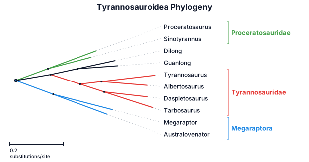
A phylogenetic tree of tyrannosauroidea, megaraptora, tyrannosauridae, and proceratosauridae
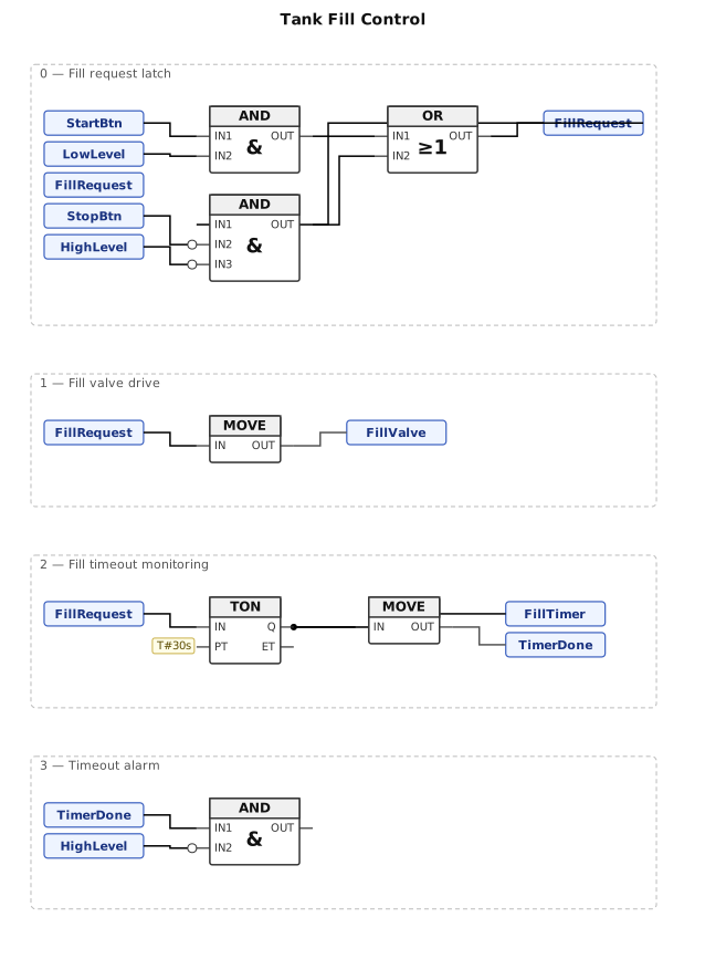
A function block diagram for a tank fill control using a TON timer and AND/OR logic
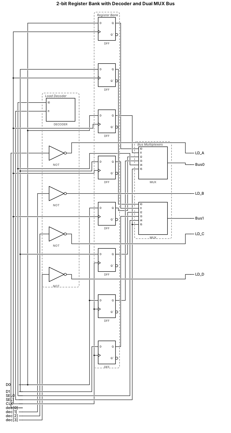
Generate a digital logic block diagram showing a 2-bit register bank (Registers A, B, C, D) connected to a 2x4 decoder for load selection and dual 4-to-1 multiplexers forming a 2-line bus.
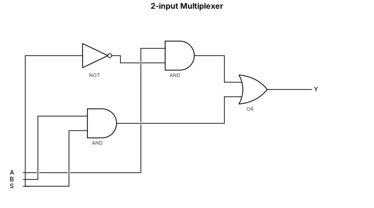
A 2-input multiplexer built from AND, OR, and NOT gates
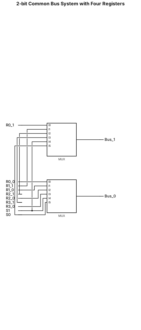
Draw a digital logic circuit for a common bus system connecting four 2-bit registers R0, R1, R2, and R3 using multiplexers only. Use exactly two 4-to-1 multiplexers. Connect the corresponding bit from each register to each multiplexer. Use shared selection lines S1 and S0. Label the two outputs Bus[1] and Bus[0]. Show a clean, academic-style circuit diagram with all wires and labels. Do not replace the multiplexers with logic gates. The circuit must select one complete 2-bit register at a time.