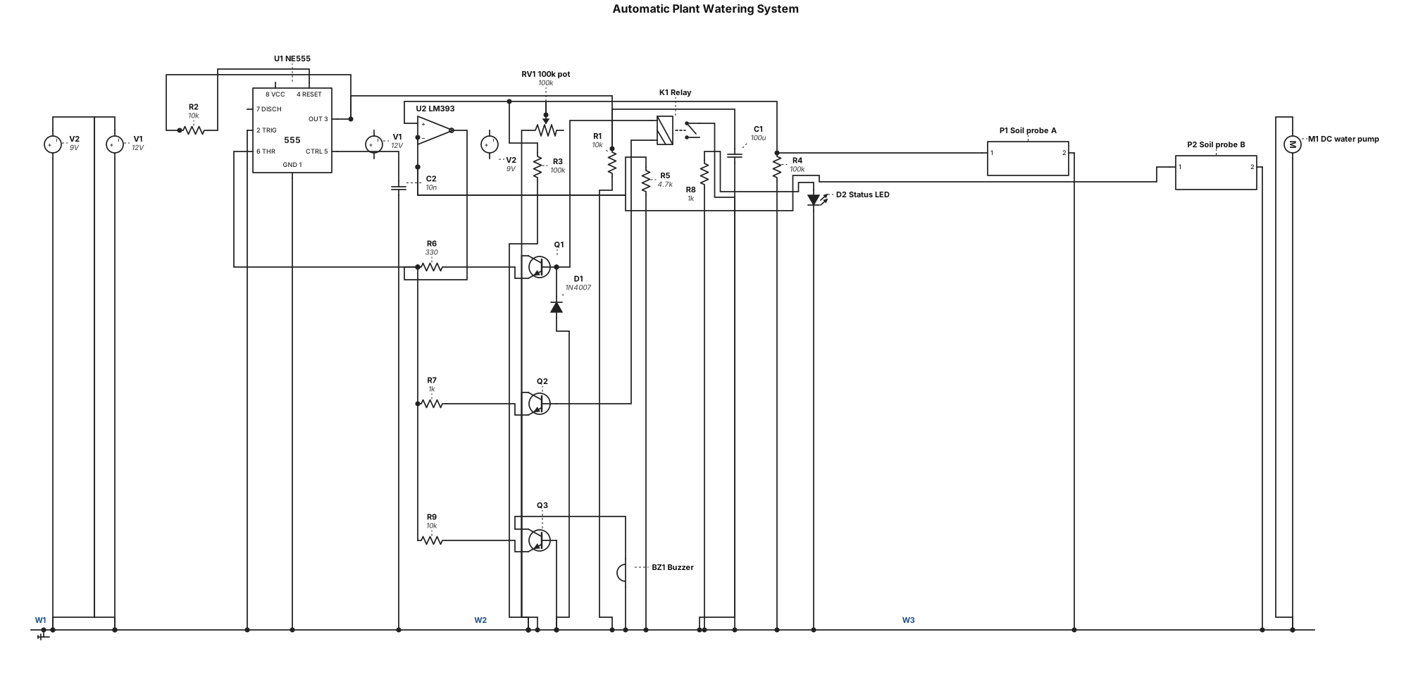
NE555 timer IC, comparator IC, 2 transistors, relay, 10 kΩ resistors (×2), 4.7 kΩ resistor, 330 Ω resistor, 100 kΩ resistor, 1 kΩ resistor, 100 kΩ potentiometer, 100 µF capacitor, 1N4007 diode, LED, buzzer, DC water pump, 9 V battery, 12 V power supply, 2 soil probes, connecting wires, and breadboard.
NODE ARCHIVE · REAL DIAGRAM BRIEFS
Diagram Examples from Real Visitor Prompts
Browse eligible diagrams shared by FreeDiagram visitors, inspect the exact prompts, and build your own version.
Browse 3261 real creationsCOMMUNITY OUTPUTS · EXACT PROMPTS
Circuit Diagrams
Showing 73–96 of 270. No stock examples or system defaults. Choose a tool, study a real result, then reopen its prompt as your starting point.
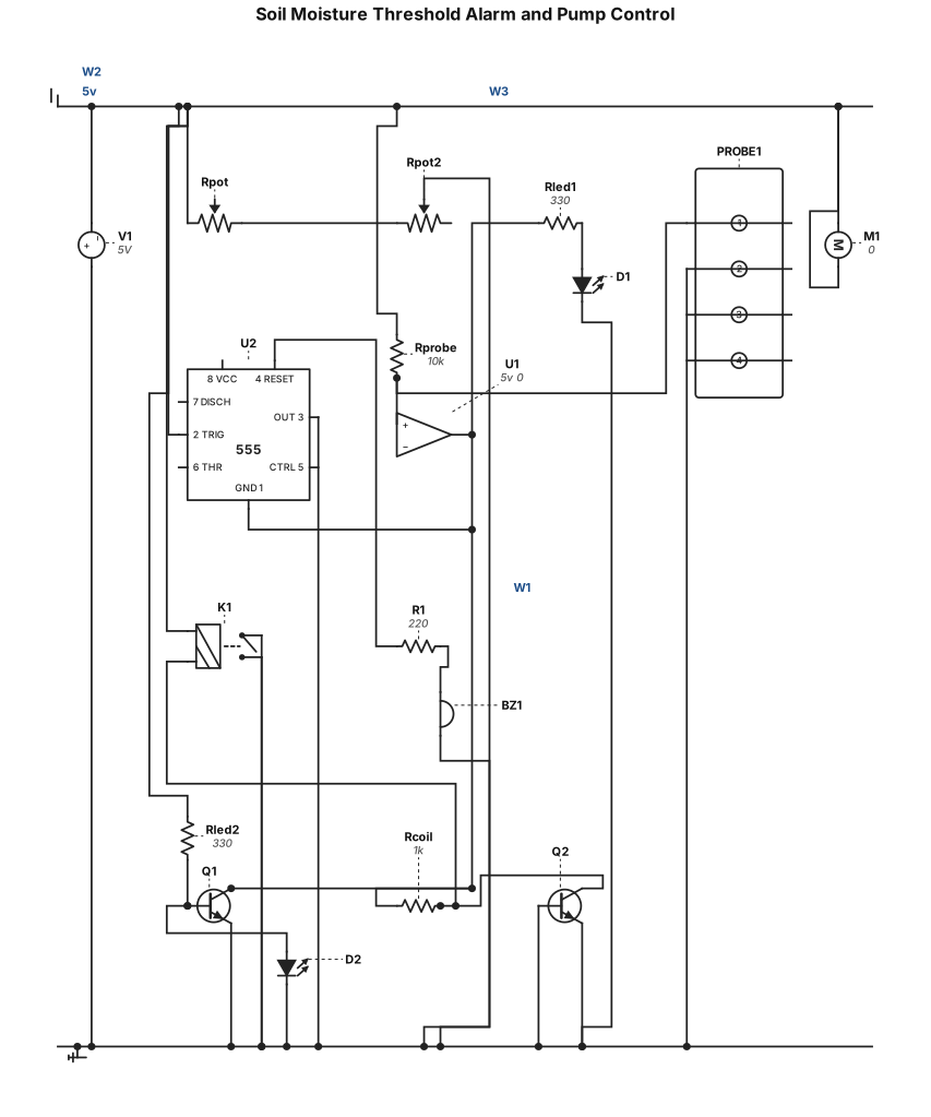
Soil sensing and threshold Connect the two soil probes between the sensor node and ground. Connect the sensor-node pull-up resistor between +5 V and the sensor node. Feed the sensor node to the LM358 IN+A input. Connect the sensitivity potentiometer’s outer legs to +5 V and GND, and its wiper to IN−A. Power the LM358 from +5 V and GND. Adjust the pot to set the dry/wet threshold. Outputs Use the LM358 output as the dry signal: for the wiring above, the sensor node should rise as the soil dries. Connect the dry signal to the 555 RESET input so the buzzer oscillator runs when dry and stops when wet. Configure the 555 as an astable oscillator; the existing timed-trigger arrangement won’t make the buzzer follow the dry state continuously. Connect the piezo to the 555 OUTPUT. Wire the red LED to turn on from the dry signal and the green LED to turn on when the dry signal is low. Put a current-limiting resistor in series with each LED. Use the dry signal to control the relay module; connect the pump motor through COM and N.O. so it runs only when the relay is energized. Check whether your relay module’s IN input is active-high or active-low before connecting it directly; use a transistor inverter if its polarity requires one. The saved circuit still needs rewiring and the LED resistors added. I can’t verify this analog circuit in Cirkit’s simulator because its LM358 and 555 parts have no simulation models. View less
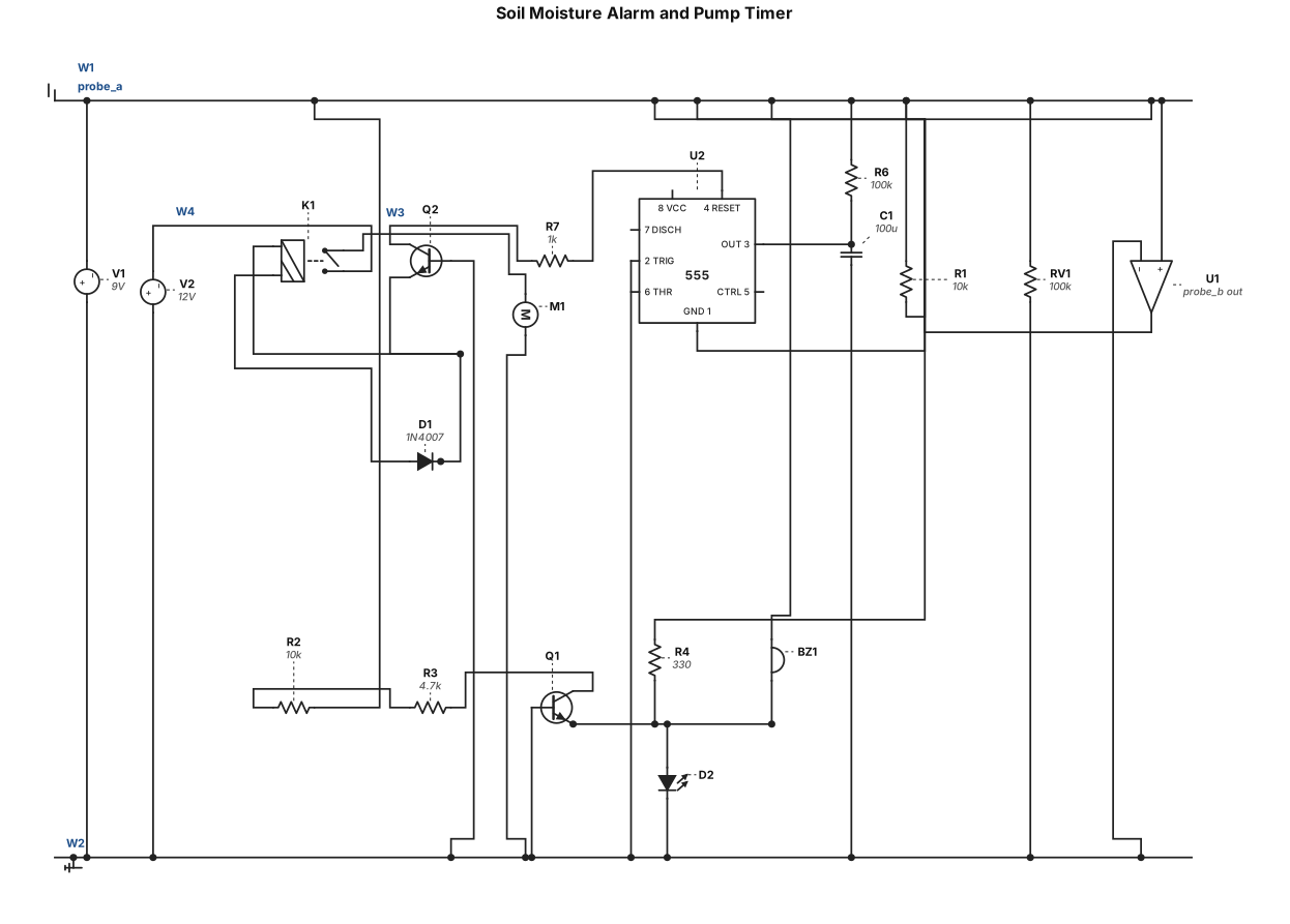
Probes + R1 + potentiometer feed the LM358, which compares wet/dry voltage and goes high when the soil is dry. That output switches on an alarm branch (R4 → Q1 → LED + buzzer) and triggers the 555 timer (R6, C1 set ~10s run time). The 555’s output drives R7 → Q2 → relay (with D1 protection) → pump, which waters the plant for that fixed time, then stops.
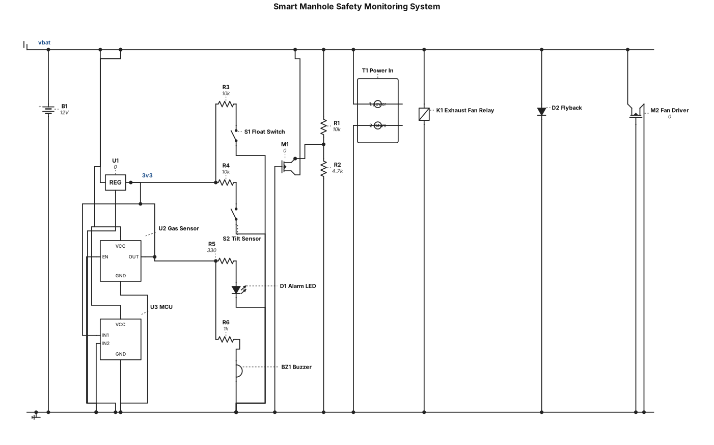
smart manhole safety monitoring system
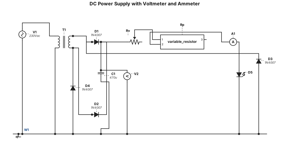
dc power supply 230V 50 hz in a square shape going to a voltmeter parallel going down to - and to Rv which goes to Rp, which is a variable resistor. it goes to an ammeter which goes to a led that goes to - and voltmeter.
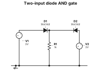
"Two-input diode AND gate: two diodes D1 and D2 with anodes connected to input A and input B respectively, cathodes tied together at the output node. A 1kΩ resistor pulls the output node to GND. Label inputs A and B, output Y, and the diodes D1, D2. Use standard 1N4148 diode symbols."
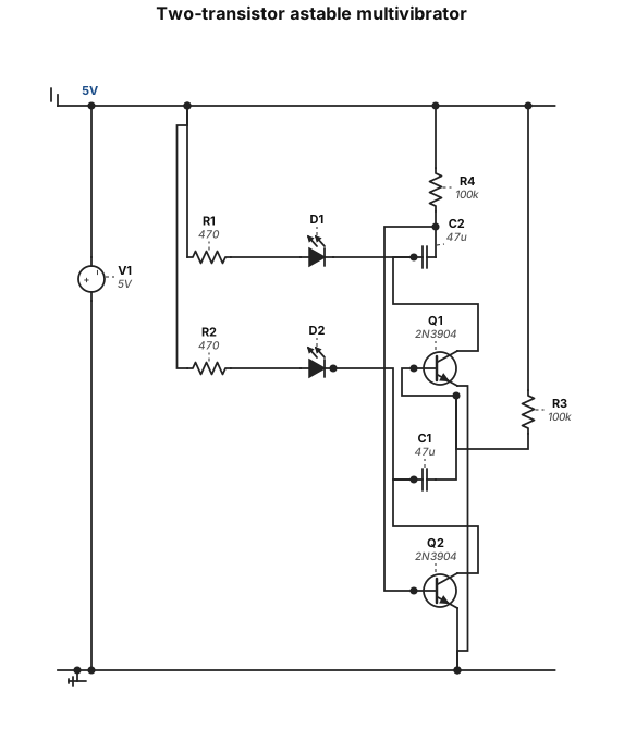
"Two-transistor astable multivibrator: two NPN transistors Q1 and Q2. Each collector has an LED in series with a 470Ω resistor to +5V. Each base is connected to +5V through a 100kΩ resistor. A 47µF capacitor cross-couples Q2's 2n3904 collector to Q1's 2n3904 base, and another 47µF capacitor cross-couples Q1's collector to Q2's base. Both emitters go to GND."
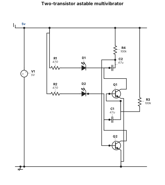
"Two-transistor astable multivibrator: two NPN transistors Q1 and Q2. Each collector has an LED in series with a 470Ω resistor to +5V. Each base is connected to +5V through a 100kΩ resistor. A 47µF capacitor cross-couples Q2's collector to Q1's base, and another 47µF capacitor cross-couples Q1's collector to Q2's base. Both emitters go to GND."
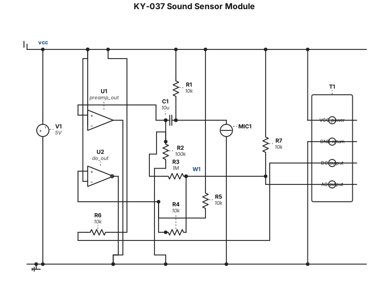
diagram dari KY-037
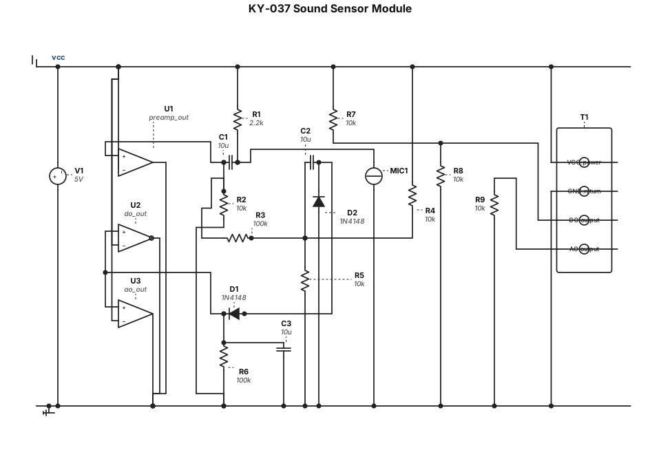
KY-037
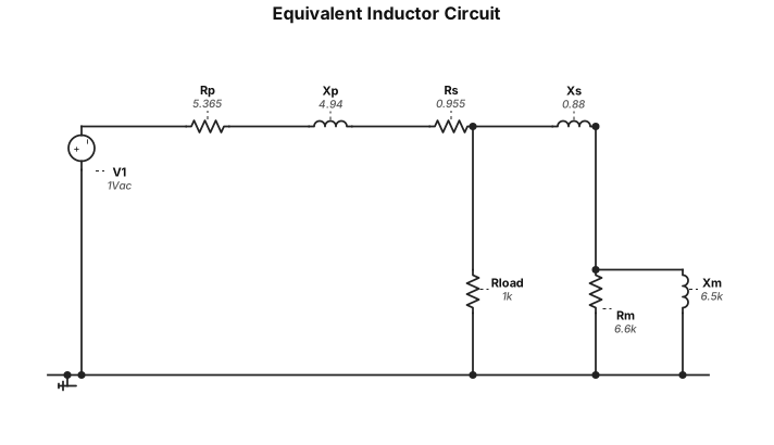
typical equivalent inductor circuit with Rp = 5.365 Rs =0.955, Xs = 0.88j Xp = 4.94i, Rm = 6.6kohm Xm = 6.5kohm
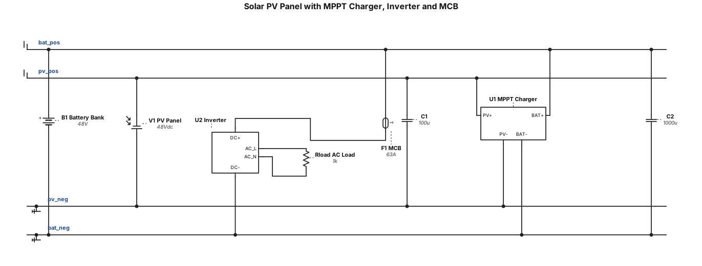
ph panel. mppt charger, inverter and mcb
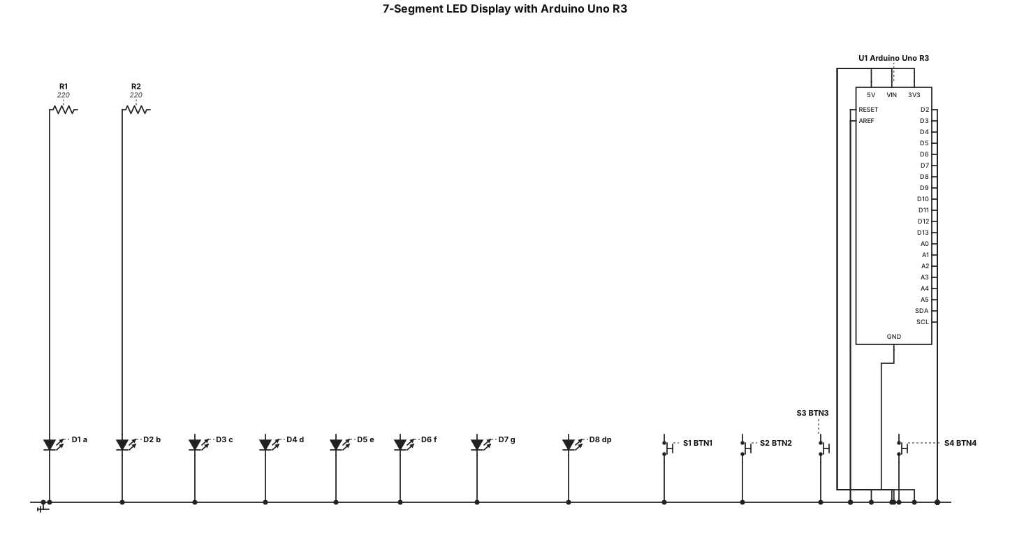
a 7 segment led display hooked up to uno r3. It only uses 2 resistors and 4 buttons. use the standard 7 segment display component diagram with the 8 led inputs. So to recap, the only components are leds, resistors, buttons.
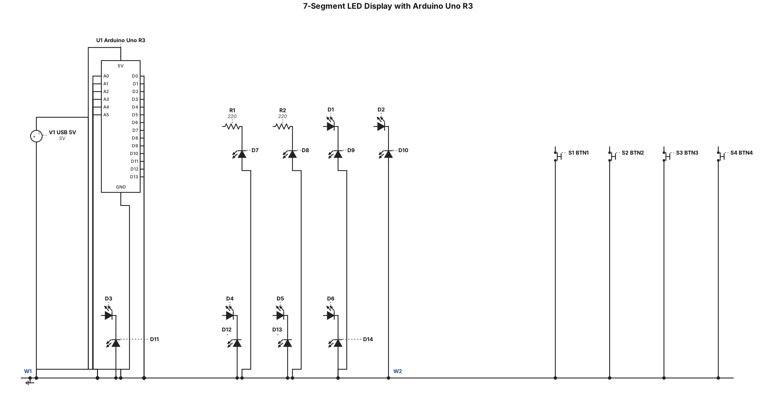
a 7 segment led display hooked up to uno r3. It only uses 2 resistors and 4 buttons. use the standard 7 segment display component diagram with the 8 led inputs
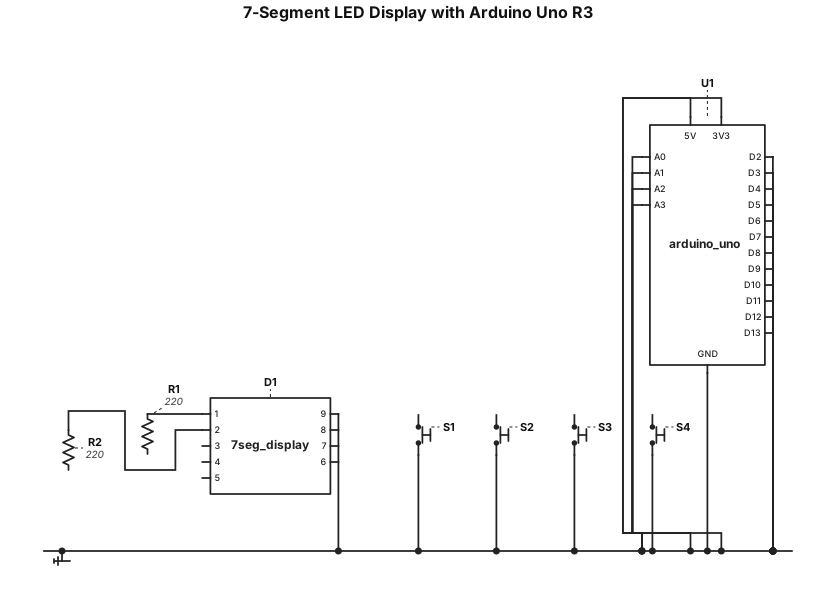
a 7 segment led display hooked up to uno r3. It only uses 2 resistors and 4 buttons.
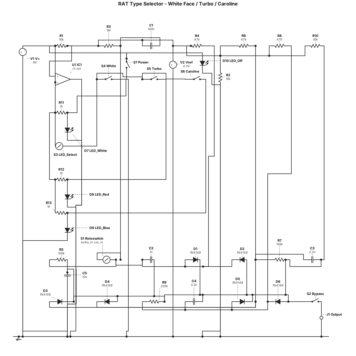
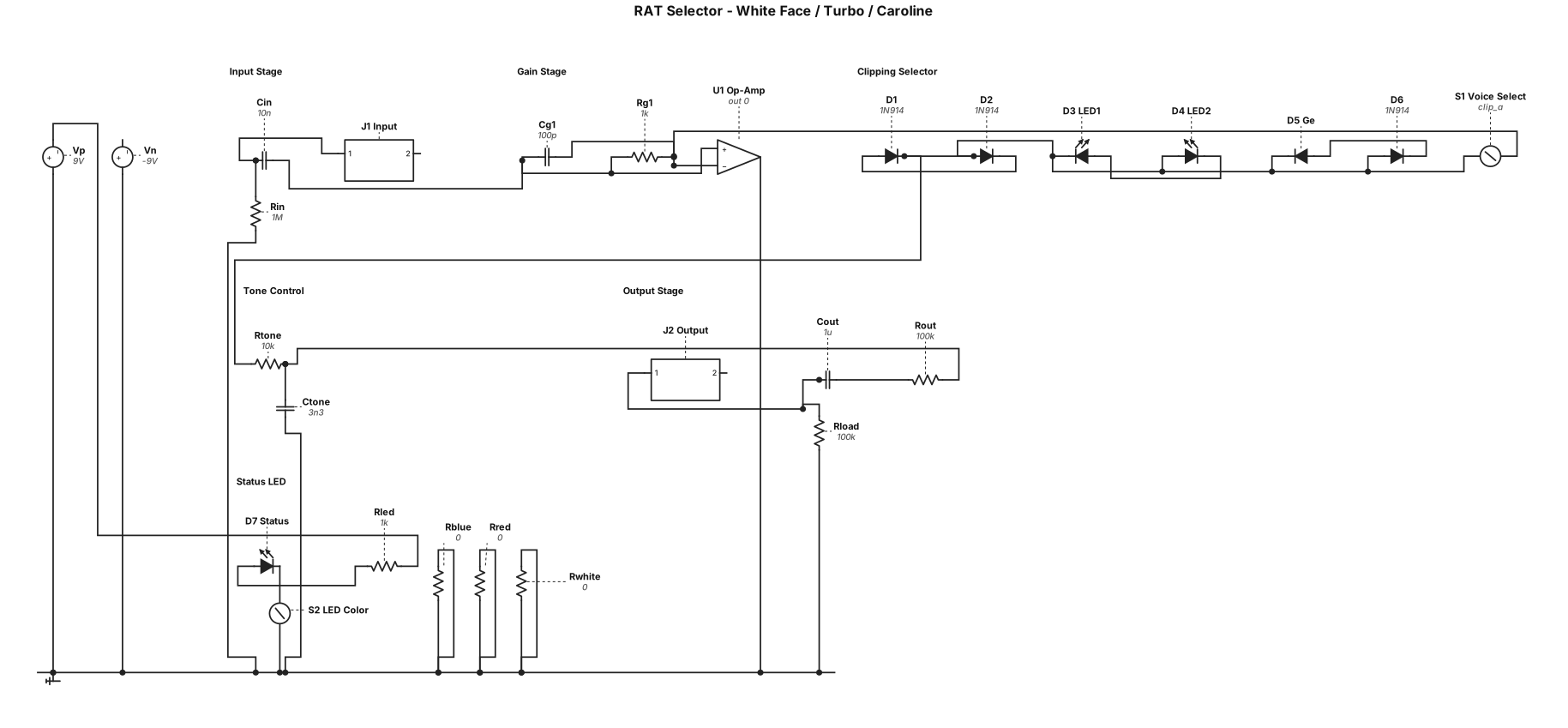
A RAT type circuit allowing to switch between the following circuits: white face RAT, Turbo Rat and Caroline. Use a rotoswitch to commute the entire circuit to the selected one. Only one ompamp. One jack output, add one status led (off: shutdown, white: white face circuit, red: turbo rat circuit, blue: Caroline circuit) Follow the same principale as JHS PackRat: Contrairement à une pédale numérique qui ferait de la simple modélisation, le bouton de sélection de la PackRat actionne un système complexe de commutateurs analogiques (40 interrupteurs internes). En tournant le bouton, la pédale modifie physiquement le chemin du signal et change les composants pour recréer le véritable circuit analogique de chaque époque. Add functional visuals indicators
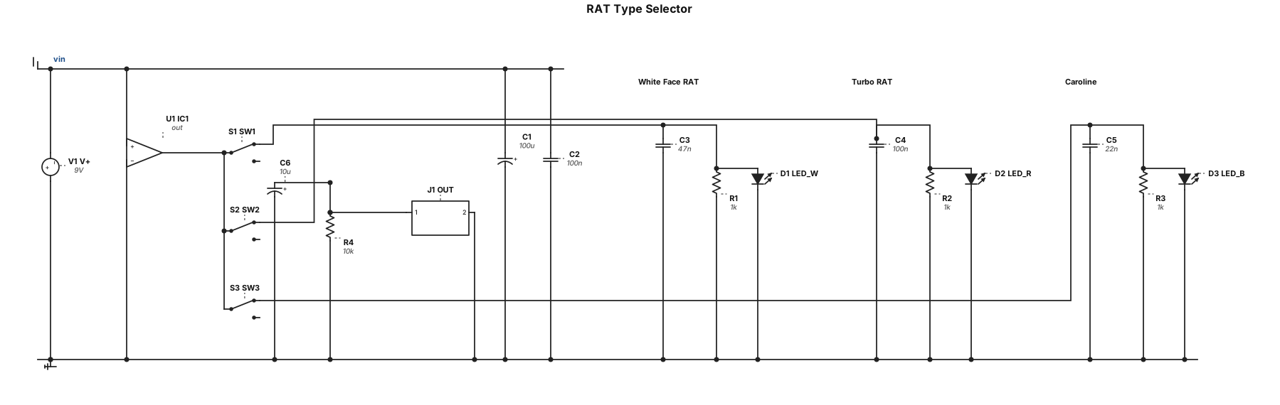
A RAT type circuit allowing to switch between the following circuits: white face RAT, Turbo Rat and Caroline. Use a rotoswitch to commute the entire circuit to the selected one. Only one ompamp. One jack output, add one status led (off: shutdown, white: white face circuit, red: turbo rat circuit, blue: Caroline circuit) Add functional visuals indicators
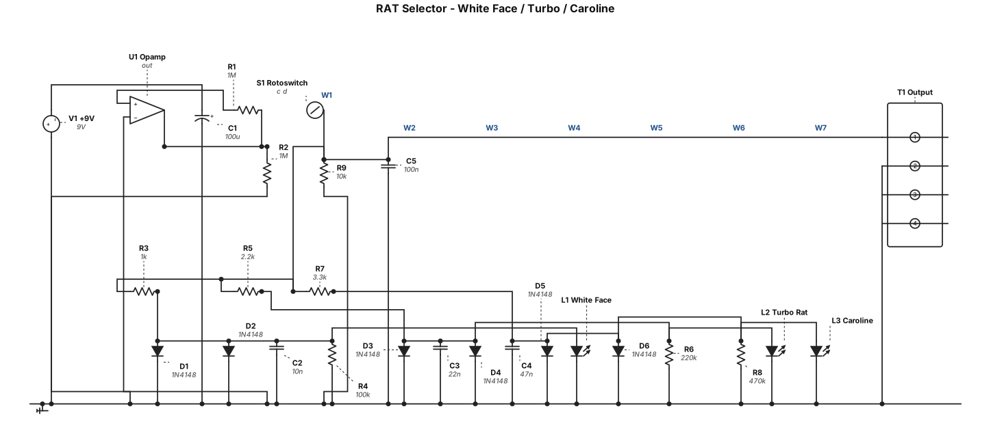
A RAT type circuit allowing to switch between the following circuits: white face RAT, Turbo Rat and Caroline. Use a rotoswitch to commute the entire circuit to the selected one. Only one ompamp. One jack output, one status led (off: shutdown, white: white face circuit, red: turbo rat circuit, blue: Caroline circuit) Add functional visuals indicators
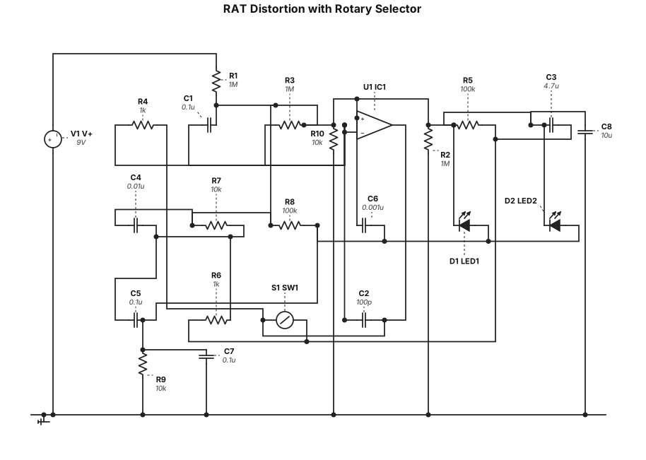
A RAT type circuit allowing to switch between the following circuits: white face RAT, Turbo Rat and Caroline. Use a rotoswitch to commute the entire circuit to the selected one. Only one ompamp. Add functional visuals indicators

A RAT type circuit allowing to switch between the following circuits: white face RAT, Turbo Rat and Caroline. Use a rotoswitch to commute the entire circuit tôt he next one. Add functional visuals indicators
A RAT type circuit allowing to switch between the following circuits: white face RAT, Turbo Rat and Caroline. Use a rotoswitch to commute the entire circuit tôt he next one
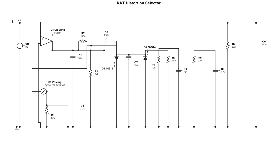
A RAT type circuit allowing to switch between the following circuits: - white face RAT - Turbo Rat - Caroline
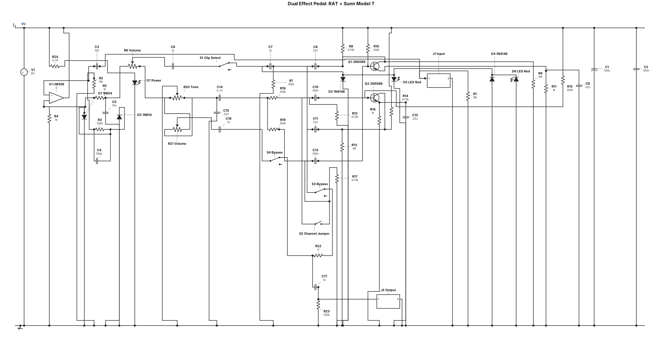
An effect pedal containing two circuits. First, a RAT type pedal, if possible with Silicon or Led type switch Second, the Sunn Models T architecture. A switch button allows to bypass it. Another one to enable the jumper between both channels.
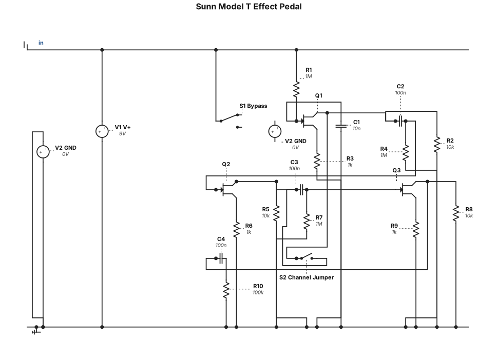
An effect pedal containing the Sunn Models T architecture. A switch button allows to bypass it. Another one to enable the jumper between both channels.