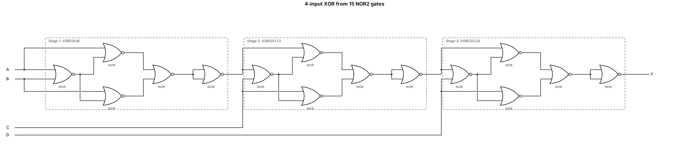
Draw a 4-input XOR gate-level schematic using EXACTLY 15 two-input NOR gates and NO other gate types. Use three cascaded XOR2 modules, five NOR2 gates per module. Only external inputs: A, B, C, D. No complemented inputs. No XOR, XNOR, NOT, NAND, AND, or OR symbols. Use exactly these connections: Stage 1: XOR2(A,B) N1 = NOR(A,B) N2 = NOR(A,N1) N3 = NOR(B,N1) N4 = NOR(N2,N3) X1 = NOR(N4,N4) Stage 2: XOR2(X1,C) N6 = NOR(X1,C) N7 = NOR(X1,N6) N8 = NOR(C,N6) N9 = NOR(N7,N8) X2 = NOR(N9,N9) Stage 3: XOR2(X2,D) N11 = NOR(X2,D) N12 = NOR(X2,N11) N13 = NOR(D,N11) N14 = NOR(N12,N13) Y = NOR(N14,N14) Draw every NOR2 gate individually with complete wires. For NOR(N4,N4), NOR(N9,N9), and NOR(N14,N14), connect both NOR inputs to the same signal. Arrange three modules left to right. Label X1, X2, and Y clearly. Final result: Y = A XOR B XOR C XOR D Total: EXACTLY 15 NOR2 gates. Do not simplify the circuit or replace gates.
Diagram Examples from Real Visitor Prompts
Browse eligible diagrams shared by FreeDiagram visitors, inspect the exact prompts, and build your own version.
Browse 3261 real creationsLogic Gate
Showing 73–96 of 288. No stock examples or system defaults. Choose a tool, study a real result, then reopen its prompt as your starting point.
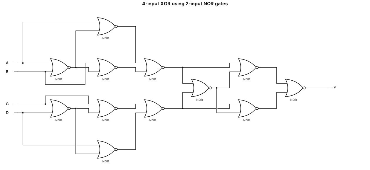
Draw a gate-level schematic of Y = A XOR B XOR C XOR D using only 2-input NOR gates.
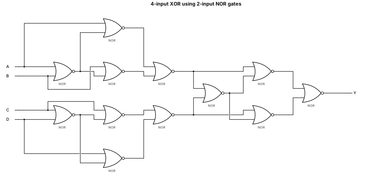
Draw a gate-level schematic of Y = A XOR B XOR C XOR D using only 2-input NOR gates.
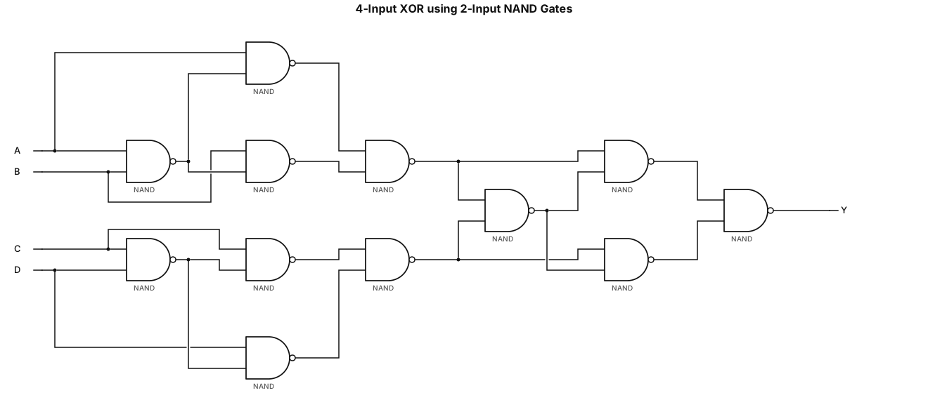
Draw a gate-level schematic of Y = A XOR B XOR C XOR D using only 2-input NAND gates.
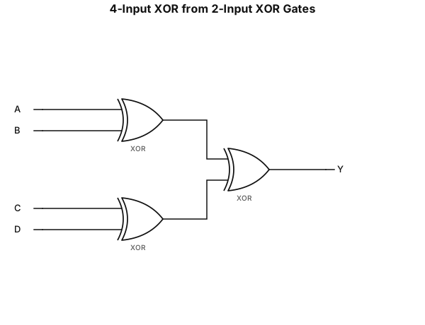
Draw a gate-level schematic of Y = A XOR B XOR C XOR D using only 2-input XOR gates.
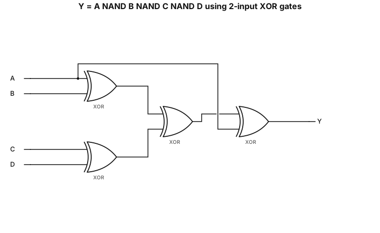
Draw a gate-level schematic of Y = A NAND B NAND C NAND D using only 2-input XOR gates.
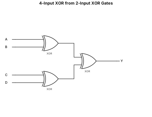
Draw a gate-level schematic of Y = A XOR B XOR C XOR D using only 2-input XOR gates.
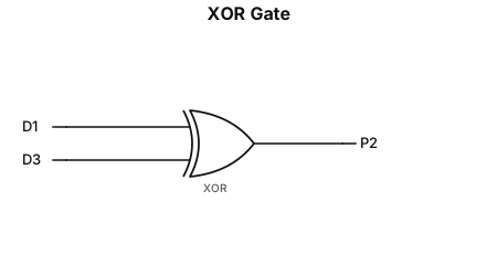
P2=xor(D1, D3)
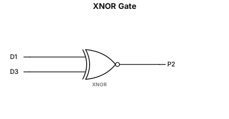
P2=xnor(D1, D3)
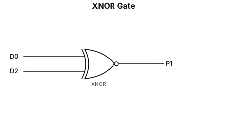
P1=xnor(D0, D2)
P1=not(xor(D0, D2))
P2=not(D1 xor D3)
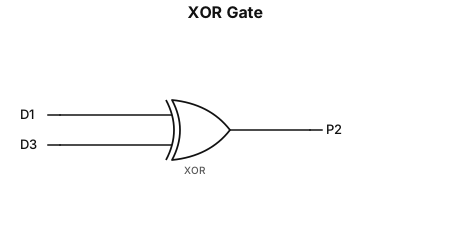
P2=D1 xor D3
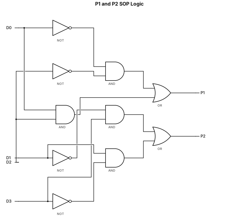
𝑃_1=SOP(m0,m3)= (𝐷_0 ) ̅ (𝐷_2 ) ̅+𝐷_0 𝐷_2 𝑃_2=SOP(m1,m2)= (𝐷_1 ) ̅ 𝐷_3+𝐷_1 (𝐷_3 ) ̅
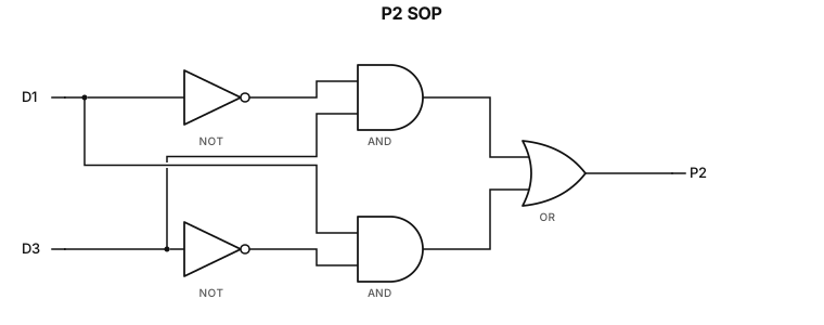
𝑃_2=SOP(m1,m2)= (𝐷_1 ) ̅ 𝐷_3+𝐷_1 (𝐷_3 ) ̅
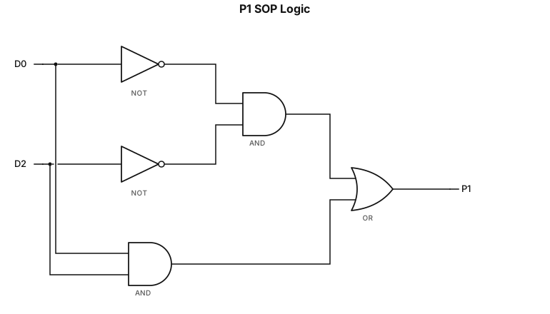
𝑃_1=SOP(m0,m3)= (𝐷_0 ) ̅ (𝐷_2 ) ̅+𝐷_0 𝐷_2
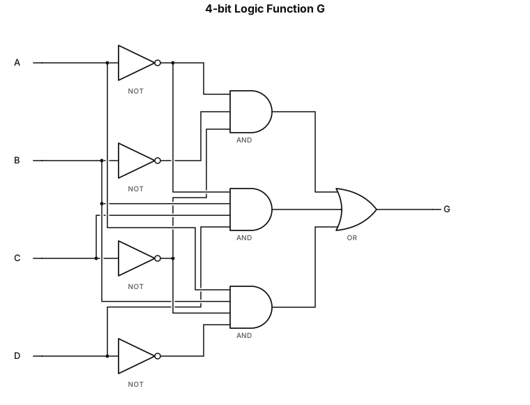
A logic gate circuit for a 4-bit binary input using AND, OR, and XOR gates with inputs A, B, C and D with function G = A'B'C' + A'BCD + ABC'D'
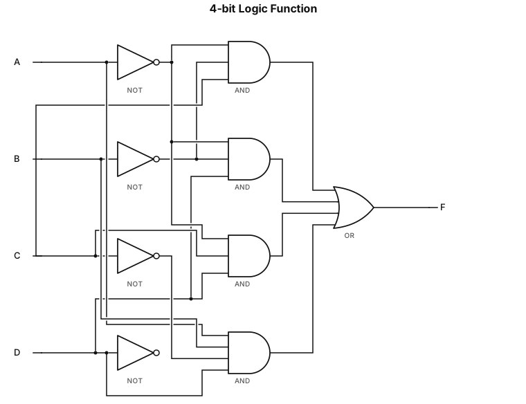
A logic gate circuit for a 4-bit binary input using AND, OR, and XOR gates with inputs A, B, C and D with function F = A'B'C + A'B'D + A'CD + ABC'D
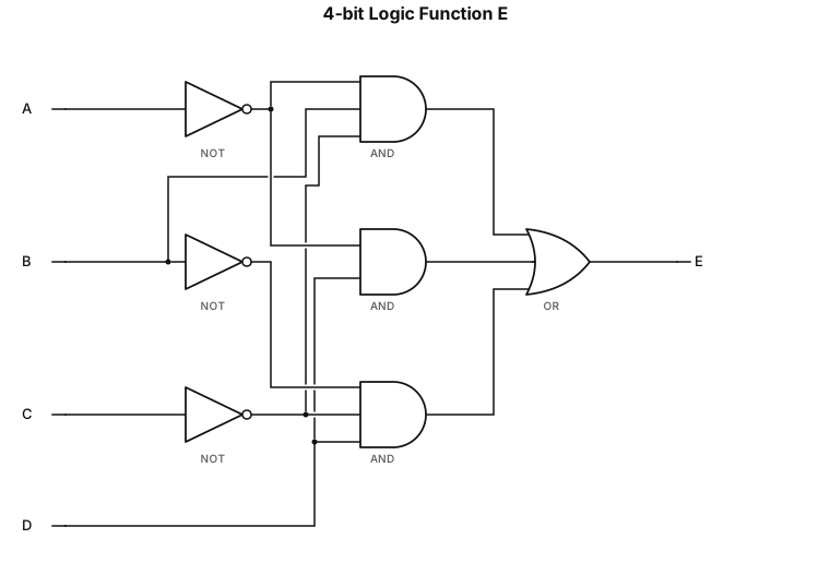
A logic gate circuit for a 4-bit binary input using AND, OR, and XOR gates with inputs A, B, C and D with function E = A'BC' + A'D + B'C'D
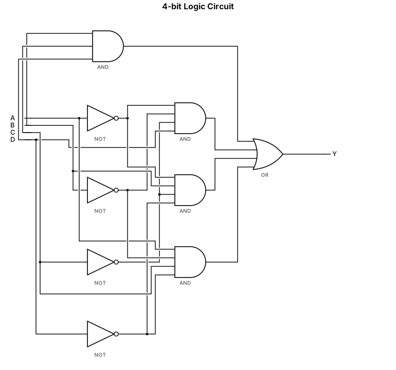
A logic gate circuit for a 4-bit binary input using AND, OR, and XOR gates with inputs A, B, C and D with function D = BCD + A'B'C'D + A'BC'D' + AB'CD'
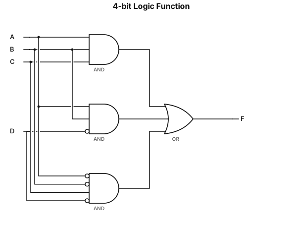
A logic gate circuit for a 4-bit binary input using AND, OR, and XOR gates with inputs A, B, C and D with function C = ABC + ABD' + A'B'CD'
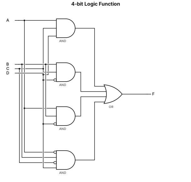
A logic gate circuit for a 4-bit binary input using AND, OR, and XOR gates with inputs A, B, C and D with function B = ACD + BCD' + ABD' + A'BC'D
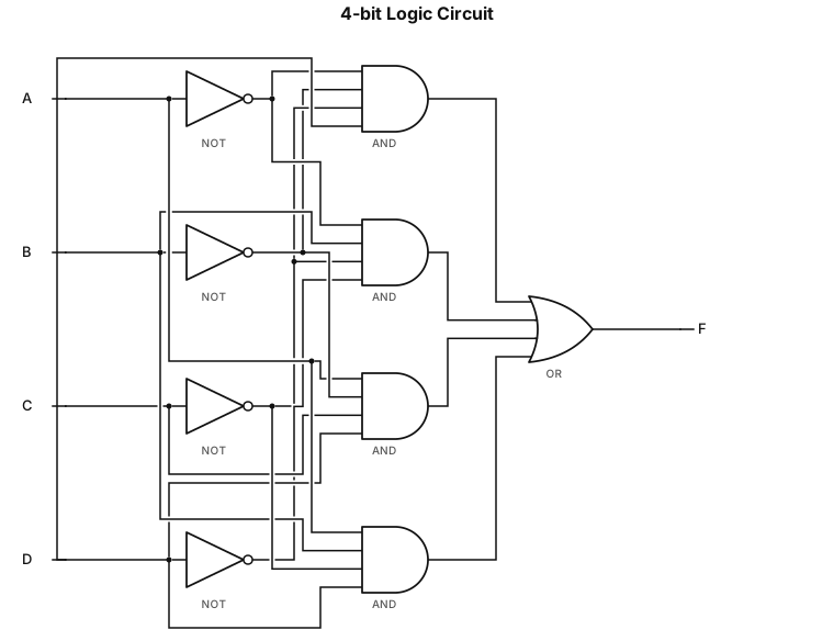
A logic gate circuit for a 4-bit binary input using AND, OR, and XOR gates with inputs A, B, C and D with function A = A'B'C'D + A'BC'D' + AB'CD + ABC'D
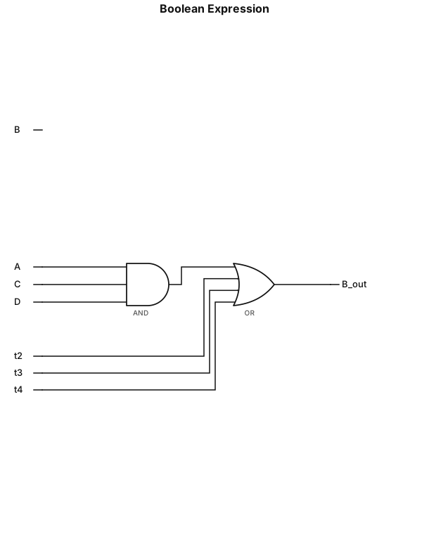
B = ACD + BCD' + ABD' + A'BC'D