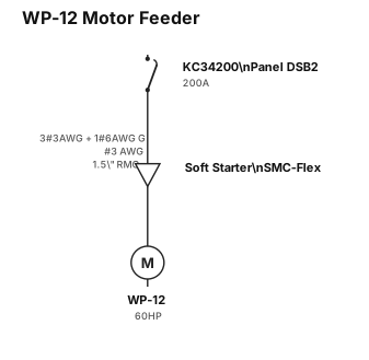
A single-line diagram that shows the a 200-amp circuit breaker (part number KC34200), in panel DSB2, feeding a motor with a soft starter. The conductor size between the soft starter and the breaker is #3AWG and the ground conductor is a #6 AWG. The conduit size between the breaker and the soft starter is 1.5" RMC. The motor is 60HP. The motor is named WP-12. Title the drawing: WP-12 Motor Feeder. The soft starter is Allen-Bradley part number: SMC-Flex.
NODE ARCHIVE · REAL DIAGRAM BRIEFS
Diagram Examples from Real Visitor Prompts
Browse eligible diagrams shared by FreeDiagram visitors, inspect the exact prompts, and build your own version.
Browse 3261 real creationsCOMMUNITY OUTPUTS · EXACT PROMPTS
Single Line Diagrams
Showing 73–96 of 196. No stock examples or system defaults. Choose a tool, study a real result, then reopen its prompt as your starting point.
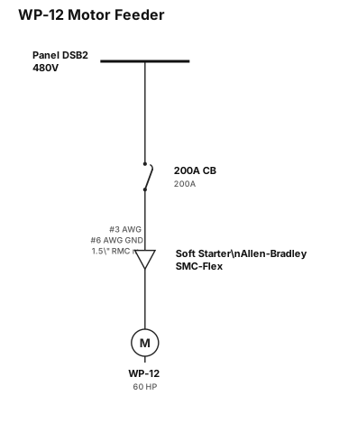
A single-line diagram that shows the a 200-amp circuit breaker, in panel DSB2, feeding a motor with a soft starter. The conductor size between the soft starter and the breaker is #3AWG and the ground conductor is a #6 AWG. The conduit size between the breaker and the soft starter is 1.5" RMC. The motor is 60HP. The motor is named WP-12. Title the drawing: WP-12 Motor Feeder. The soft starter is Allen-Bradley part number: SMC-Flex.
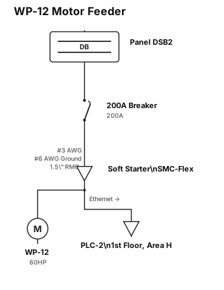
A single-line diagram that shows the a 200 amp breaker, in panel DSB2, feeding a motor with a soft starter. The conductor size between the soft starter and the breaker is #3AWG and the ground conductor is a #6 AWG. The conduit size between the breaker and the soft starter is 1.5" RMC. The motor is 60HP. The motor is named WP-12. Title the drawing: WP-12 Motor Feeder. The soft starter is Allen-Bradley part number: SMC-Flex. Coming out of the soft starter, please show a ethernet cable with an arrow showing that it should be ran to PLC-2 on the 1st floor of Area H
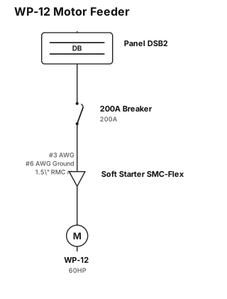
A single-line diagram that shows the a 200 amp breaker, in panel DSB2, feeding a motor with a soft starter. The conductor size between the soft starter and the breaker is #3AWG and the ground conductor is a #6 AWG. The conduit size between the breaker and the soft starter is 1.5" RMC. The motor is 60HP. The motor is named WP-12. Title the drawing: WP-12 Motor Feeder. The soft starter is Allen-Bradley part number: SMC-Flex.
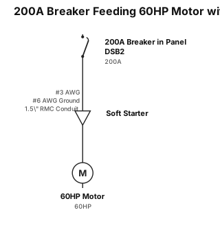
A single-line diagram that shows the a 200 amp breaker, in panel DSB2, feeding a motor with a soft starter. The conductor size between the soft starter and the breaker is #3AWG and the ground conductor is a #6 AWG. The conduit size between the breaker and the soft starter is 1.5" RMC. The motor is 60HP
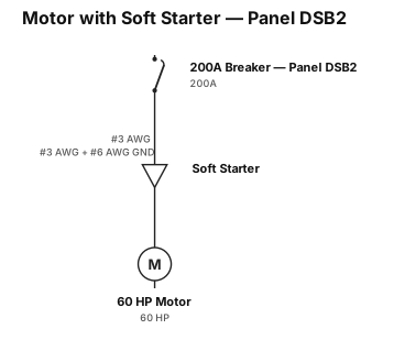
A single-line diagram that shows the a 200 amp breaker, in panel DSB2, feeding a motor with a soft starter. The conductor size between the soft starter and the breaker is #3AWG and the ground conductor is a #6 AWG. The motor is 60HP
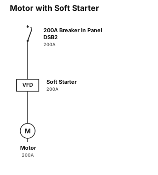
A single-line diagram that shows the a 200 amp breaker, in panel DSB2, feeding a motor with a soft starter
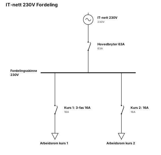
IT-nett 230V, main breaker 63 A, branch 1 3 fas 16A in workroom, branch 2 16A in workroom
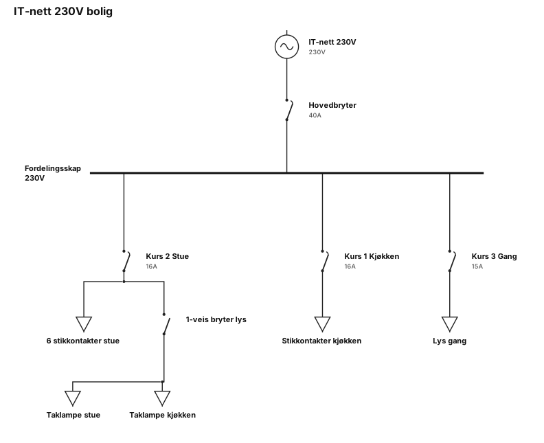
IT-nett 230V, main breaker 40A, branch 1 16A kitchen, branch 2 16A living room. 6 contacts in living room. 1 switch for light in the celling for both rooms. need a hall between rooms branch 3 15A
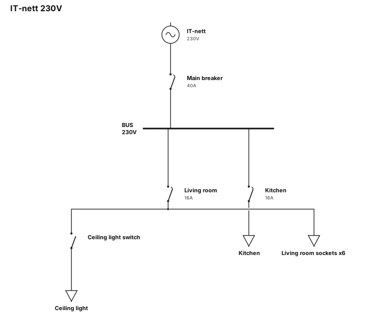
IT-nett 230V, main breaker 40A, branch 1 16A kitchen, branch 2 16A living room. 6 contacts in living room. 1 switch for light in the celling for both rooms
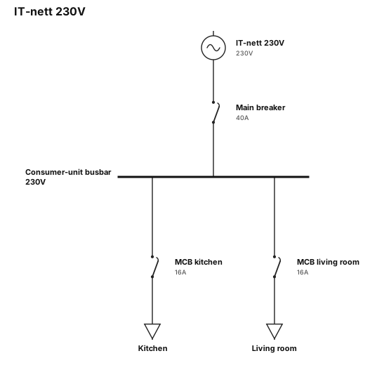
IT-nett 230V, main breaker 40A, branch 1 16A kitchen, branch 2 16A living room
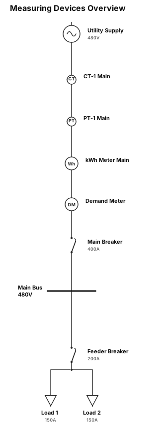
measuring devices
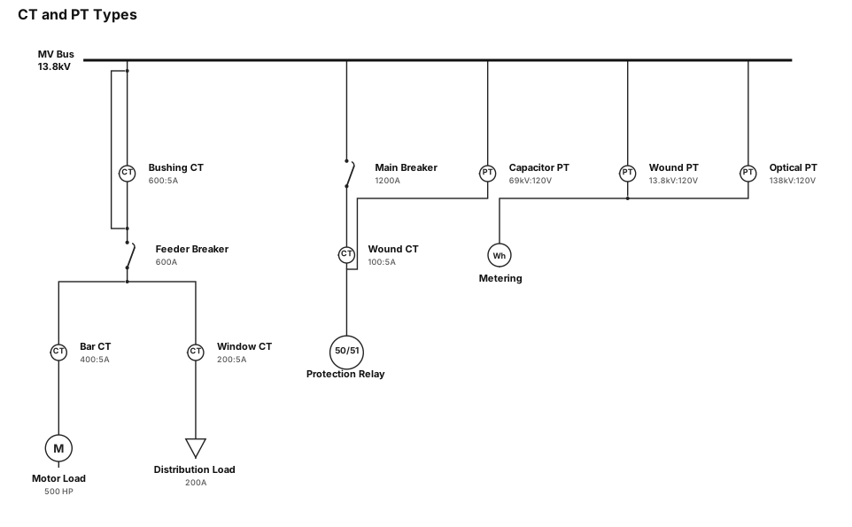
CT and PT and there types
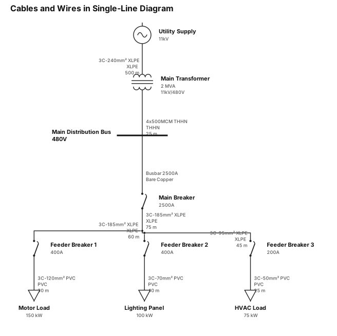
cables and wires used in SLD like only wires and cables
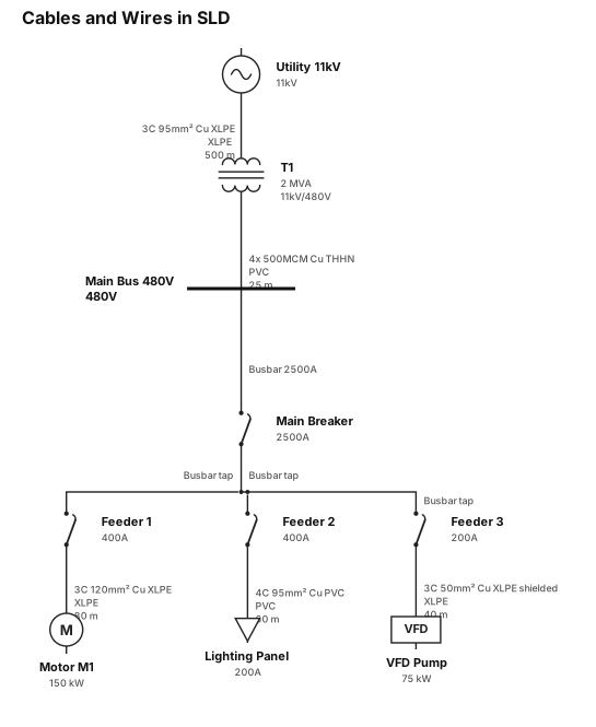
cables and wires used in SLD

circuit breaker and types of circuit breaker
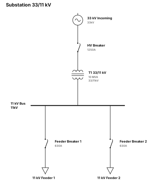
a substation 33/11 kv
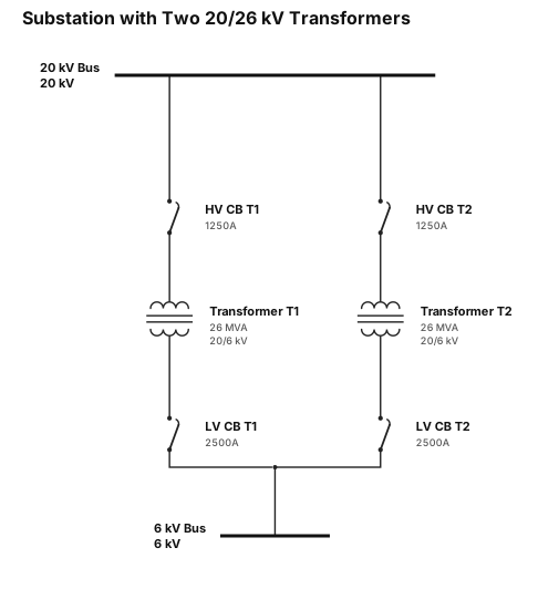
A single-line diagram for a substation with 2 20/26 transformaer
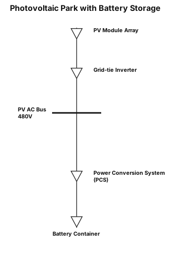
hey, i want to generate a simple sld for a photovoltaic parc. It sohould include a PV Module, an inverter, then this system should be connected to a battery system, this system whould consisst of a pcs and a battery container
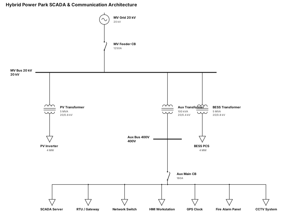
Scada and communication architecture single-line diagram for hybrid (solar+battery storage) power park. MV voltage line is 20 kV. Auxiliray power.
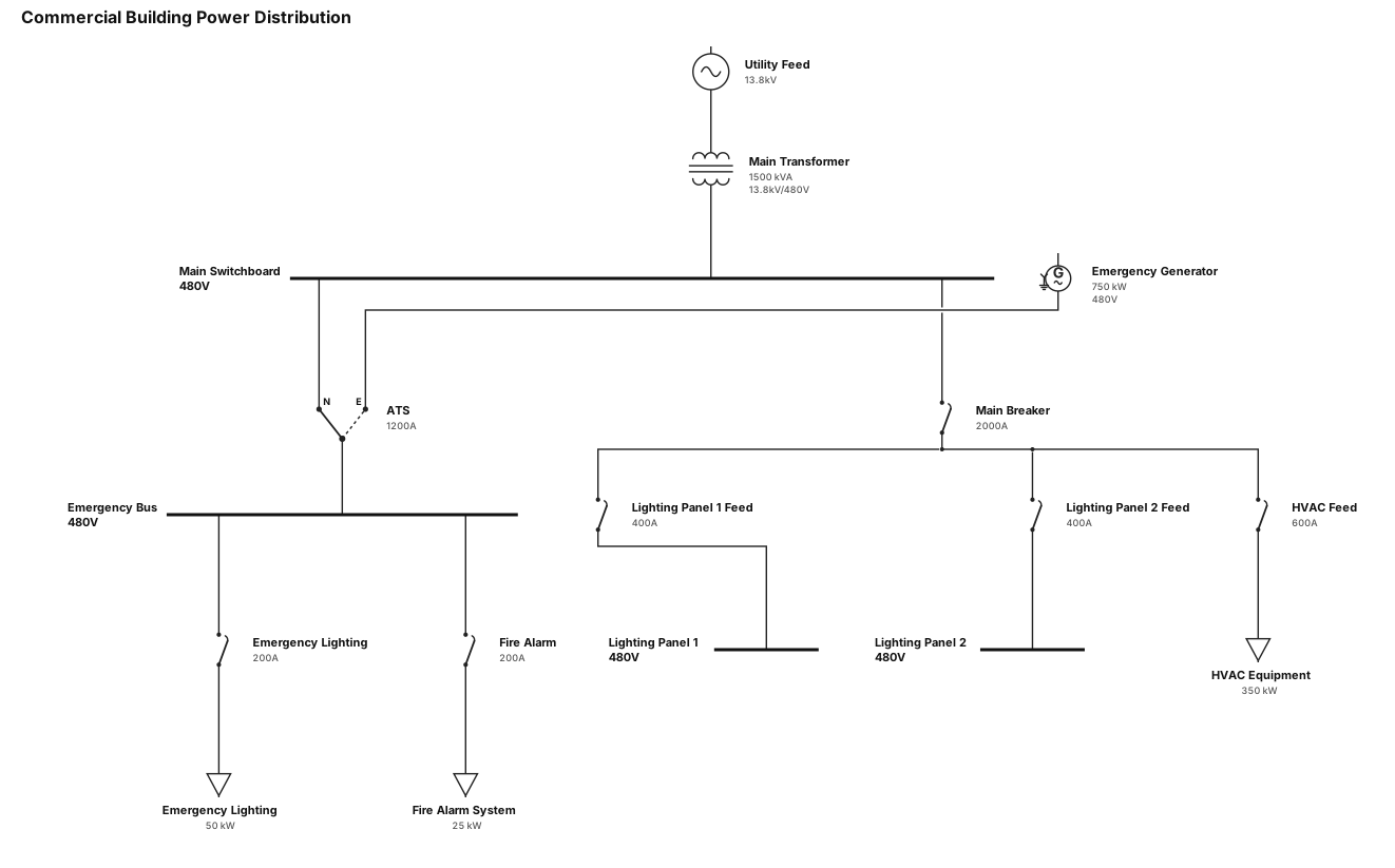
A single-line diagram for a commercial building: utility feed through a main transformer to a 480V switchboard, then to lighting panels, HVAC equipment, and an emergency generator with ATS
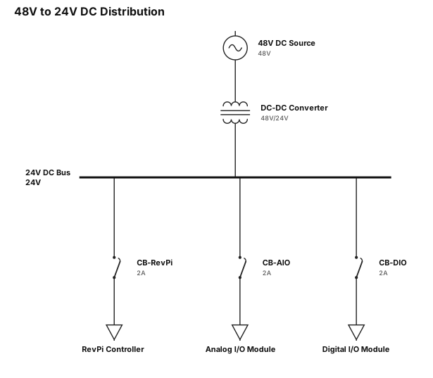
A single-line diagram for 48v -> DCDC 24v -> Revpi, AIO, DIO
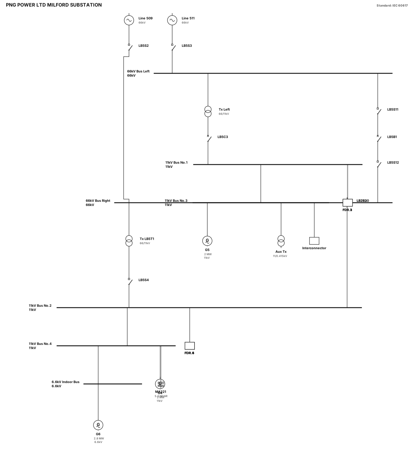
Technical report Single-Line Diagram for "PNG POWER LTD MILFORD SUBSTATION", clean black lines on white background, standard IEC/IEEE symbols: - 66kV Sectionalized Busbar: Single horizontal bar split in the middle by in-line isolator LB5S11, breaker LB5B1, and isolator LB5S12. - Incomers: Top line 511 (with LB5S3) feeds left 66kV bus; line 509 (with LB5S2) feeds right 66kV bus. - Transformers: Left 66/11kV Tx fed via breaker LB5C3 to 11kV Bus 1; Right 66/11kV Tx LB5T1 fed via isolator LB5S4 to 11kV Bus 2. - 11kV Main Buses: Bus No.1 and Bus No.2 parallel below. Connected vertically by Bus Coupler LB2B2 and Bus Tie LB2B30. - Feeders: Exactly 6 outgoing feeders at bottom labeled FDR.1, FDR.2, FDR.3 (on Bus 1) and FDR.4, FDR.5, FDR.6 (on Bus 2). - Extension Buses: 11kV Bus No.3 & No.4 with Generators G5 (2MW) and G4 (2MW), Aux Tx, MA221 5.0 MVAR, Interconnector line, and 6.6kV Indoor Bus with Generator G6 (2.8MW). Style: Engineering schematic, sharp black lines, clean orthogonal routing, horizontal busbars, proper IEC text labels.
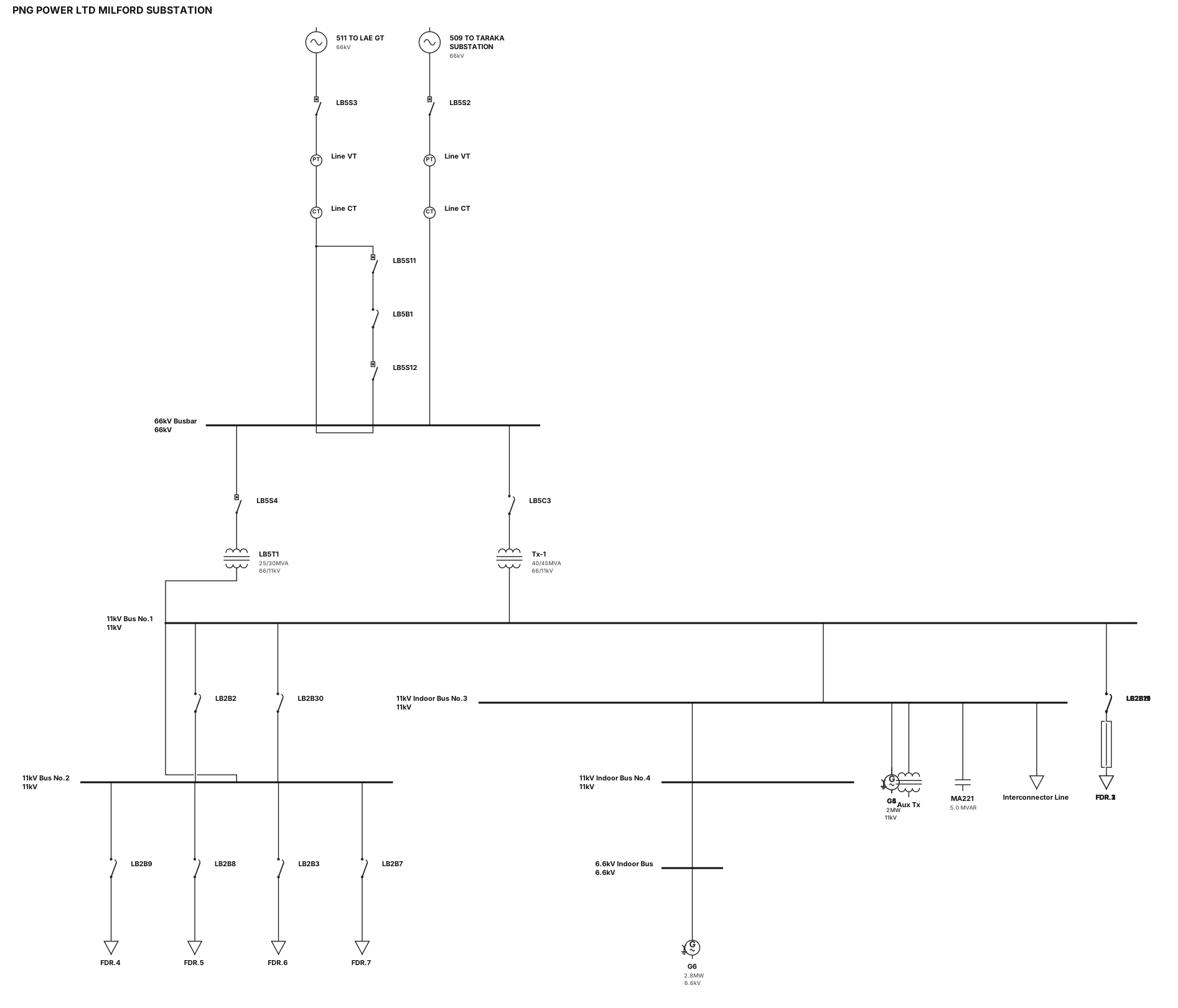
SCADA single-line diagram vector for "PNG POWER LTD MILFORD SUBSTATION" on dark gray background. Exact topology: - Top Lines: Incomers "511 TO LAE GT" and "509 TO TARAKA SUBSTATION" with isolators LB5S3, LB5S2, and line VT/CTs. - 66kV Busbar: Horizontal line with bus sectionalizer breaker "LB5B1" flanked by isolators LB5S11 & LB5S12. - Power Transformers: Left 66/11kV 40/45MVA Tx via breaker LB5C3; Right 66/11kV 25/30MVA Tx "LB5T1" via isolator LB5S4. - 11kV Busbars: Bus No.1 & Bus No.2 (connected via bus coupler LB2B2 and bus tie LB2B30) feeding Feeders FDR.1 to FDR.6 (breakers LB2B21, LB2B19, LB2B11, LB2B9, LB2B8, LB2B3, LB2B7). - Right Extensions: 11kV Indoor Bus No.3 & No.4 with Generators G5 (2MW) & G4 (2MW), Aux Tx, MA221 5.0 MVAR, Interconnector line, and 6.6kV Indoor Bus with G6 (2.8MW). Style: Flat vector, orthogonal 90-degree lines, crisp white labels. ALL breakers, isolators, and switches MUST be rendered as simple solid black square blocks with clean borders.