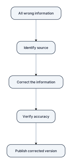
all wrong information
NODE ARCHIVE · REAL DIAGRAM BRIEFS
Diagram Examples from Real Visitor Prompts
Browse eligible diagrams shared by FreeDiagram visitors, inspect the exact prompts, and build your own version.
Browse 3285 real creationsCOMMUNITY OUTPUTS · EXACT PROMPTS
All visitor creations
Showing 1105–1128 of 3285. No stock examples or system defaults. Choose a tool, study a real result, then reopen its prompt as your starting point.
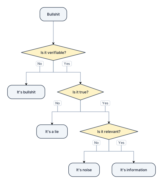
bullshit
"Arduino Pro Micro with SHT31 I2C sensor at 0x44, 16x2 LCD I2C at 0x27, SSR on pin 4, three buttons with pull-ups on pins 5-7, NPN transistor driver for 24V SSR control"
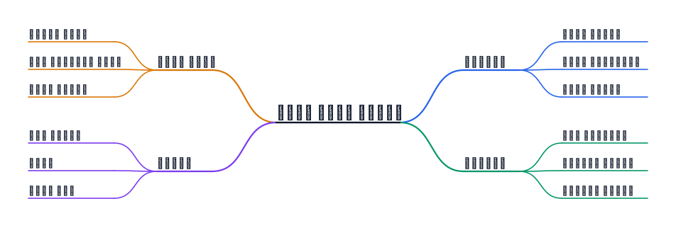
استخدام مصفا بدون اي اسلاك كاهيكل وا ايضا المطاط للحصول علي افضل خدمه وا قناصه
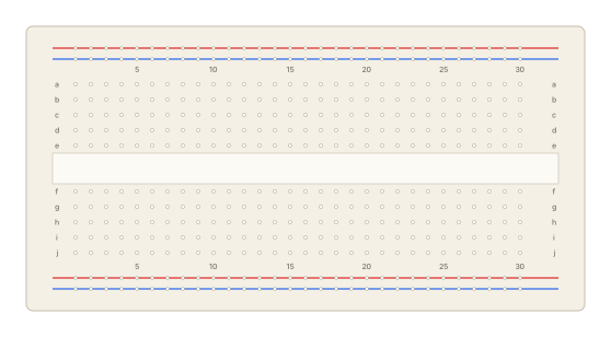
Arduino Pro Micro MCU, SHT31 temperature/humidity sensor on I2C bus (SDA pin A4, SCL pin A5, address 0x44), 16x2 I2C LCD display (address 0x27), solid-state relay on digital pin 4 with NPN transistor driver (2N2222, 1kΩ base resistor, 10kΩ base-GND), three tactile push buttons on pins 5, 6, 7 wired to GND with internal pull-ups, 5V and GND rails shared across I2C bus.
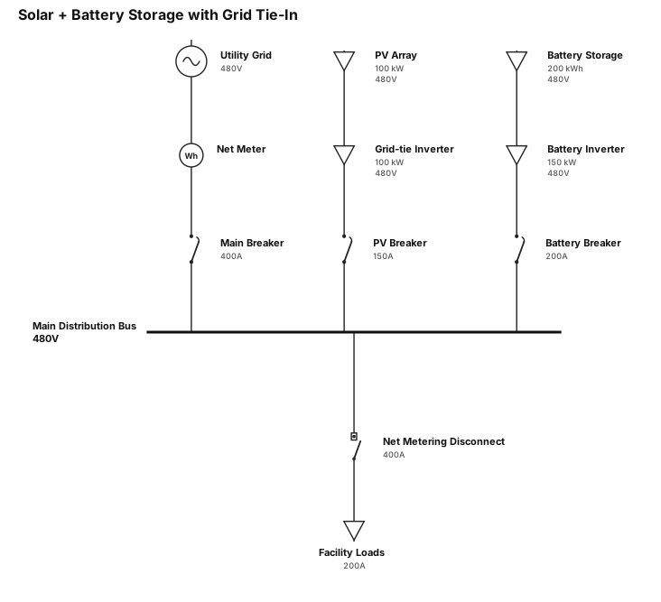
Solar plus battery storage and grid tie-in with inverter and net metering disconnect
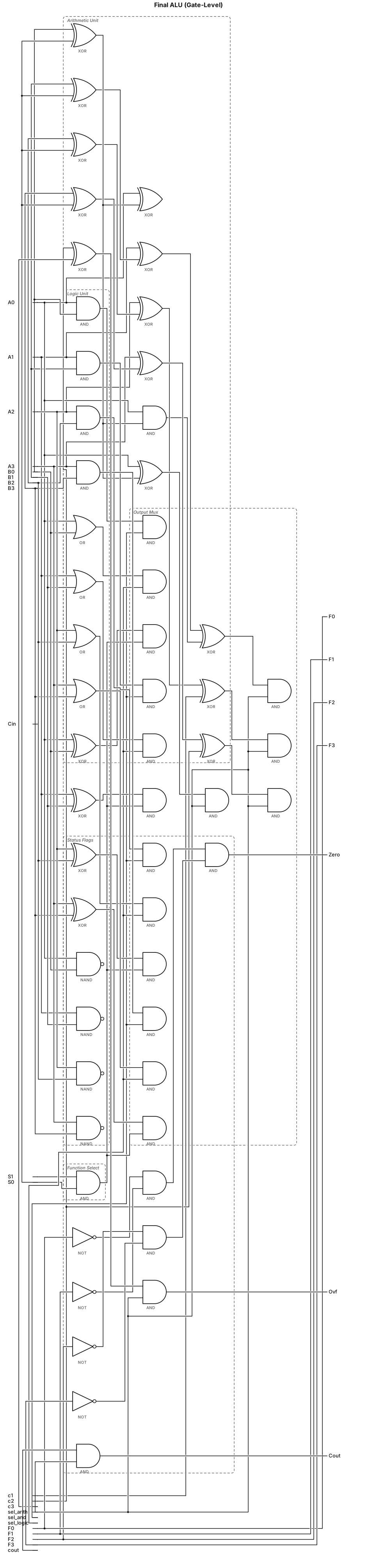
Gate-level schematic for the final ALU design
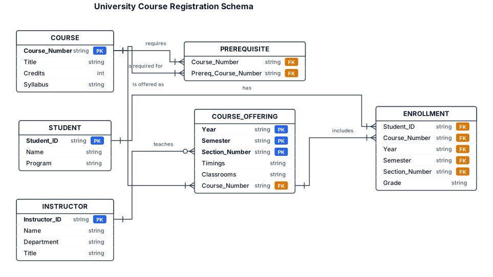
erDiagram COURSE { string Course_Number PK string Title int Credits string Syllabus } COURSE_OFFERING { string Year PK string Semester PK string Section_Number PK string Timings string Classrooms string Course_Number FK "Identifying relationship" } STUDENT { string Student_ID PK string Name string Program } INSTRUCTOR { string Instructor_ID PK string Name string Department string Title } ENROLLMENT { string Student_ID FK string Course_Number FK string Year FK string Semester FK string Section_Number FK string Grade "Relationship Attribute" } PREREQUISITE { string Course_Number FK string Prereq_Course_Number FK } %% Relationships COURSE ||--o{ COURSE_OFFERING : "is offered as" COURSE ||--o{ PREREQUISITE : "requires" COURSE ||--o{ PREREQUISITE : "is required for" INSTRUCTOR }|--o{ COURSE_OFFERING : "teaches" STUDENT ||--o{ ENROLLMENT : "has" COURSE_OFFERING ||--o{ ENROLLMENT : "includes"

An org chart for 20 people for a Hotel Management with 2 departments

An org chart for a 30-person startup with a CEO, CTO, CMO, and VP of Sales at the top — then engineering, product, marketing, and sales teams below with their leads
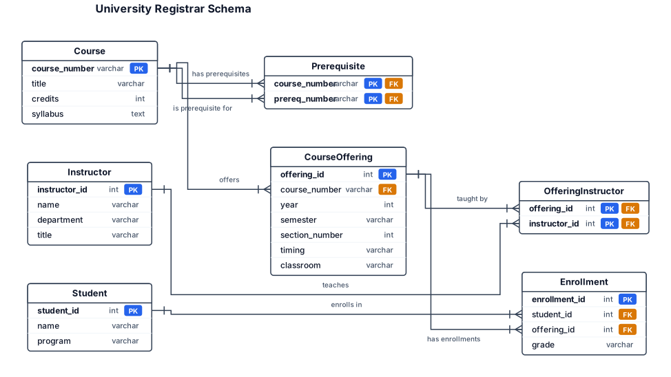
A university registrar's office maintains data about the following entities: c. courses, including number, title, credits, syllabus, and prerequisites; d. course offerings, including course number, year, semester, section number, instructors), timings and classrooms; e. students, including student-id, name, and program; and f. instructors, including identification number, name, department, and title. Further, the enrolment of students in courses and grades awarded to students in each course they are enrolled for must be appropriately modeled. Construct an E-R diagram for the registrar's office. Document all assumptions that you make about the mapping constraints
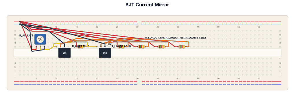
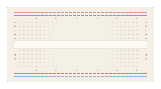
Simple BJT current mirror circuit with two NPN transistors, two 10k resistors, three 1.5k load resistors, one 10k variable resistor, and five test points. Show the components arranged neatly on a simple breadboard. Label Q1, Q2, R_adjust, R_limit, R_load1, R_load2, R_load3, R_load4, TP1, TP2, TP3, TP4, TP5, V+ and GND.
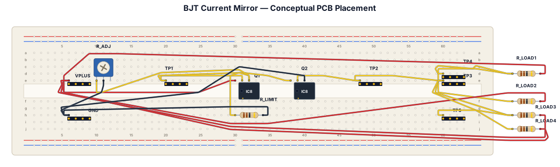
Create a simple academic conceptual PCB placement diagram for a BJT Current Mirror circuit. Use a rectangular PCB outline and show the approximate physical placement of Q1, Q2, R_adjust 10 kΩ variable resistor, R_limit 10 kΩ, R_load1 1.5 kΩ, R_load2 1.5 kΩ, R_load3 1.5 kΩ, R_load4 10 kΩ, TP1, TP2, TP3, TP4, TP5, V+ and GND. Place Q1 and Q2 close together. Place R_adjust near the edge of the PCB for easy adjustment. Arrange the load resistors neatly in sequence and place TP1–TP5 along the measurement path. Make it look like a simple student engineering PCB planning sketch, clean black lines, white background, minimal labels, no decorative elements, no realistic 3D rendering, no unnecessary components. Do not assume transistor model, package, footprint, or PCB dimensions. This is a conceptual PCB placement plan, not a final PCB design.
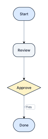
Create a flowchart: Start → Review → Approve → Done. Keep these four labels exactly.
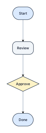
Create a flowchart: Start → Review → Approve → Done. Keep these four labels exactly.
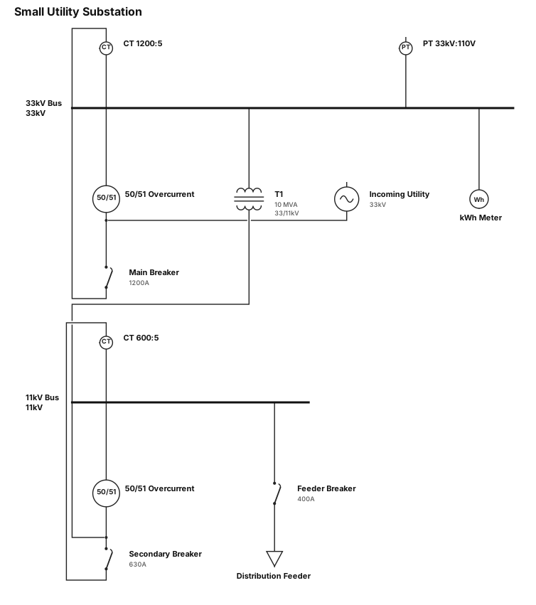
Small utility substation with protection relays and metering
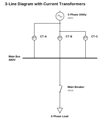
draw a 3-line diagram with a current transformer around each line
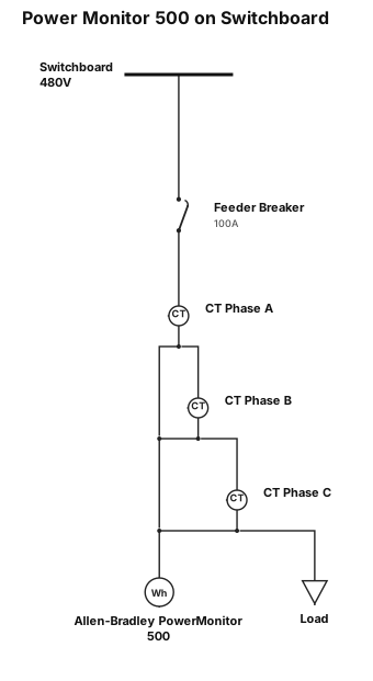
Draw a box that houses a Allen-Bradley Power Montior 500 that connects to a typical switchboard with a CT on each phase
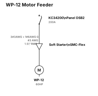
A single-line diagram that shows the a 200-amp circuit breaker (part number KC34200), in panel DSB2, feeding a motor with a soft starter. The conductor size between the soft starter and the breaker is #3AWG and the ground conductor is a #6 AWG. The conduit size between the breaker and the soft starter is 1.5" RMC. The motor is 60HP. The motor is named WP-12. Title the drawing: WP-12 Motor Feeder. The soft starter is Allen-Bradley part number: SMC-Flex.
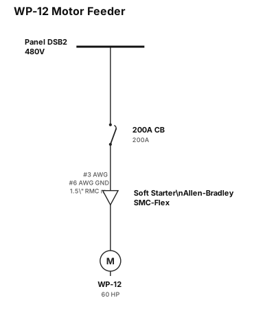
A single-line diagram that shows the a 200-amp circuit breaker, in panel DSB2, feeding a motor with a soft starter. The conductor size between the soft starter and the breaker is #3AWG and the ground conductor is a #6 AWG. The conduit size between the breaker and the soft starter is 1.5" RMC. The motor is 60HP. The motor is named WP-12. Title the drawing: WP-12 Motor Feeder. The soft starter is Allen-Bradley part number: SMC-Flex.
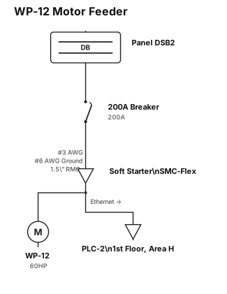
A single-line diagram that shows the a 200 amp breaker, in panel DSB2, feeding a motor with a soft starter. The conductor size between the soft starter and the breaker is #3AWG and the ground conductor is a #6 AWG. The conduit size between the breaker and the soft starter is 1.5" RMC. The motor is 60HP. The motor is named WP-12. Title the drawing: WP-12 Motor Feeder. The soft starter is Allen-Bradley part number: SMC-Flex. Coming out of the soft starter, please show a ethernet cable with an arrow showing that it should be ran to PLC-2 on the 1st floor of Area H
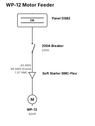
A single-line diagram that shows the a 200 amp breaker, in panel DSB2, feeding a motor with a soft starter. The conductor size between the soft starter and the breaker is #3AWG and the ground conductor is a #6 AWG. The conduit size between the breaker and the soft starter is 1.5" RMC. The motor is 60HP. The motor is named WP-12. Title the drawing: WP-12 Motor Feeder. The soft starter is Allen-Bradley part number: SMC-Flex.
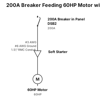
A single-line diagram that shows the a 200 amp breaker, in panel DSB2, feeding a motor with a soft starter. The conductor size between the soft starter and the breaker is #3AWG and the ground conductor is a #6 AWG. The conduit size between the breaker and the soft starter is 1.5" RMC. The motor is 60HP
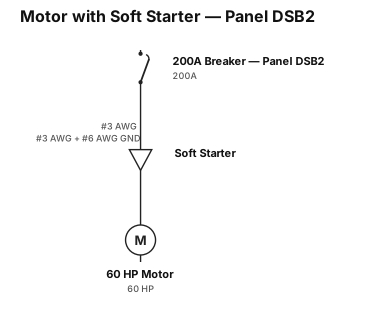
A single-line diagram that shows the a 200 amp breaker, in panel DSB2, feeding a motor with a soft starter. The conductor size between the soft starter and the breaker is #3AWG and the ground conductor is a #6 AWG. The motor is 60HP