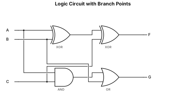
1. 输入:A,B,C 2.F 通路: - XOR1 输入 A、B;XOR1 输出接 XOR2 输入 1;XOR2 输入 2 接 C;XOR2 输出 = F 3.G 通路: - AND 输入 A、C;AND 输出接 OR 输入 1;OR 输入 2 接 B;OR 输出 = G 4. 导线分叉处自动出现**实心黑点**,就是题目要求的分叉标记。
NODE ARCHIVE · REAL DIAGRAM BRIEFS
Diagram Examples from Real Visitor Prompts
Browse eligible diagrams shared by FreeDiagram visitors, inspect the exact prompts, and build your own version.
Browse 3285 real creationsCOMMUNITY OUTPUTS · EXACT PROMPTS
All visitor creations
Showing 1153–1176 of 3285. No stock examples or system defaults. Choose a tool, study a real result, then reopen its prompt as your starting point.
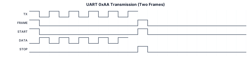
two serial UART 0xAA transmissions with start and stop bits identified
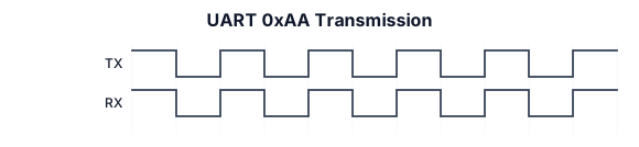
two serial UART 0xAA transmissions
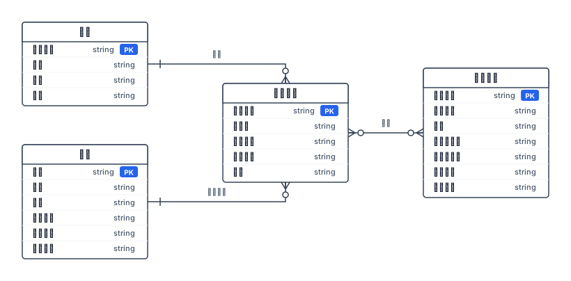
师生体检管理系统 ER 图需求描述 一、系统概述 本系统为师生体检管理系统,用于管理校内师生体检业务,记录体检参与信息、医生送检信息、体检报告以及各项检验检测结果,实现体检全流程数据存储与管理。系统包含 4 个实体:医生、师生、体检报告、检验项目,实体间通过送检、参加体检、检测三类联系建立关联。 二、实体及属性定义 医生 描述:执行送检操作的医护人员。 属性:医生工号(主键)、姓名、职称、科别。 师生 描述:参与体检的校内教师与学生。 属性:工号(主键)、姓名、性别、人员类别、所属部门、联系电话。 体检报告 描述:单次体检生成的一份报告,一份报告对应一位师生。 属性:报告编号(主键)、样品号、送检日期、体检年份、诊断。 检验项目 描述:体检中单项检验项目(如血常规、肝功能等),保存项目基础参考标准。 属性:项目代码(主键)、项目名称、单位、参考值下限、参考值上限、项目类别、在用标志。 三、实体间联系定义 联系:送检(医生 ↔ 体检报告) 基数:1 对多(1:n) 含义:一名医生可以提交多份体检报告,一份体检报告仅由一名医生送检。 联系:参加体检(师生 ↔ 体检报告) 基数:1 对多(1:n) 含义:一名师生可以产生多份体检报告(历年多次体检);一份体检报告仅属于一位师生。 联系:检测(体检报告 ↔ 检验项目) 基数:多对多(m:n) 含义:一份体检报告包含多项检验项目;同一个检验项目可出现在多份体检报告中。 联系自带属性:结果值、异常标志(保存本次体检该项目的实测结果,仅属于本次检测关联,不属于实体)。 四、业务规则 医生使用工号唯一标识,可对师生发起体检送检,生成体检报告。 师生凭工号登记体检,每年 / 多次体检可生成多份独立体检报告。 每份体检报告可绑定多条检验项目检测记录,记录该项目本次检测的结果数值与是否异常标记。 检验项目为基础字典数据,维护项目名称、单位、正常参考区间,供所有体检报告复用。 五、E-R 图结构总结 实体:医生、师生、体检报告、检验项目 1:n 联系:医生 - 送检 - 体检报告;师生 - 参加体检 - 体检报告 m:n 联系:体检报告 - 检测 - 检验项目(联系属性:结果值、异常标志)
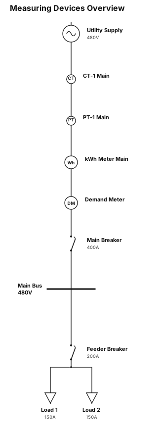
measuring devices
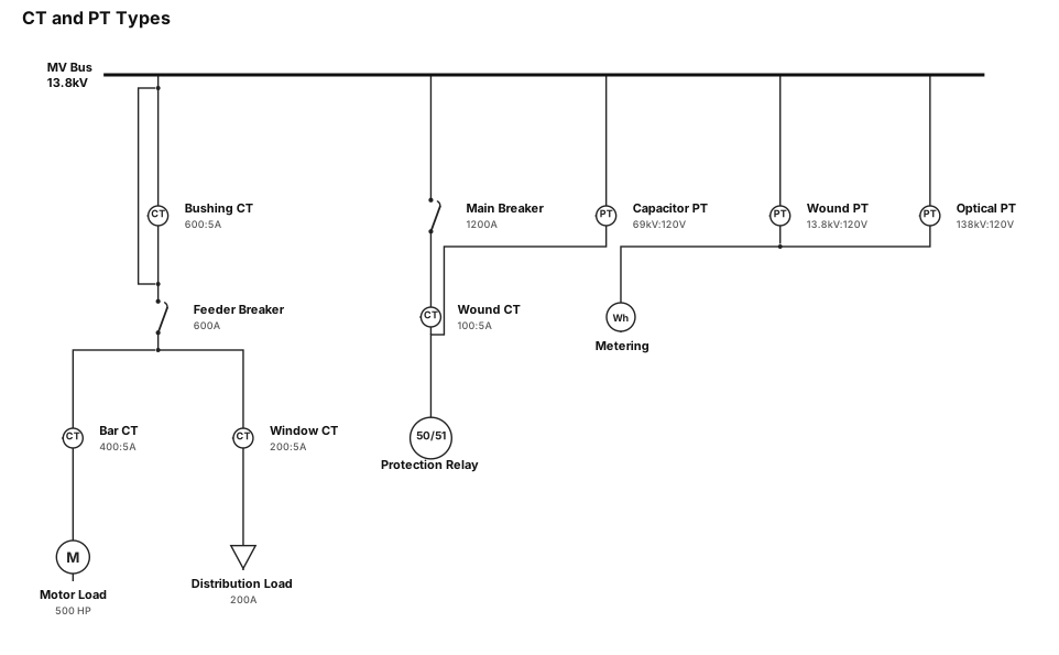
CT and PT and there types
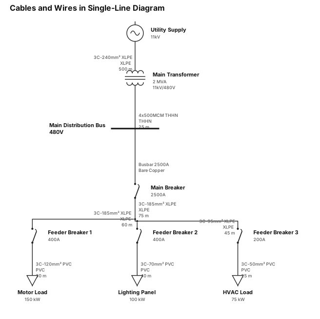
cables and wires used in SLD like only wires and cables
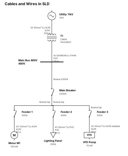
cables and wires used in SLD

circuit breaker and types of circuit breaker
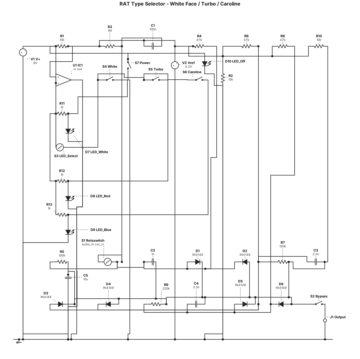
A RAT type circuit allowing to switch between the following circuits: white face RAT, Turbo Rat and Caroline. Use a rotoswitch to commute the entire circuit to the selected one. Only one ompamp. One jack output, add one status led (off: shutdown, white: white face circuit, red: turbo rat circuit, blue: Caroline circuit) Follow the same principale as JHS PackRat: Contrairement à une pédale numérique qui ferait de la simple modélisation, le bouton de sélection de la PackRat actionne un système complexe de commutateurs analogiques (40 interrupteurs internes). En tournant le bouton, la pédale modifie physiquement le chemin du signal et change les composants pour recréer le véritable circuit analogique de chaque époque. Add functional visuals indicators
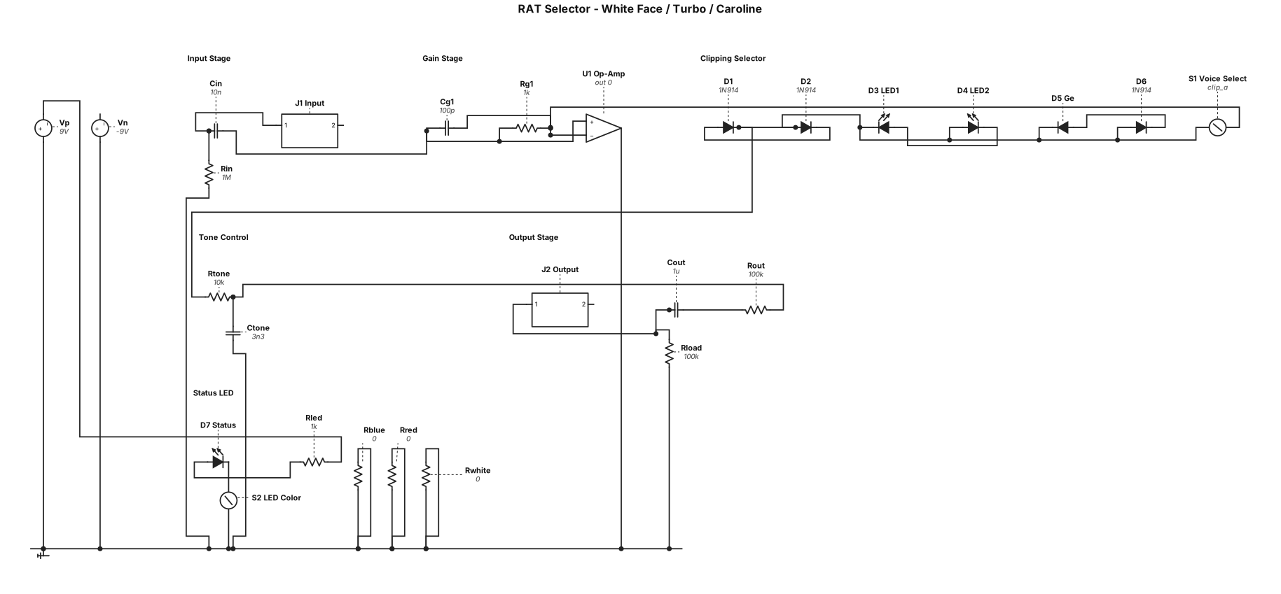
A RAT type circuit allowing to switch between the following circuits: white face RAT, Turbo Rat and Caroline. Use a rotoswitch to commute the entire circuit to the selected one. Only one ompamp. One jack output, add one status led (off: shutdown, white: white face circuit, red: turbo rat circuit, blue: Caroline circuit) Add functional visuals indicators
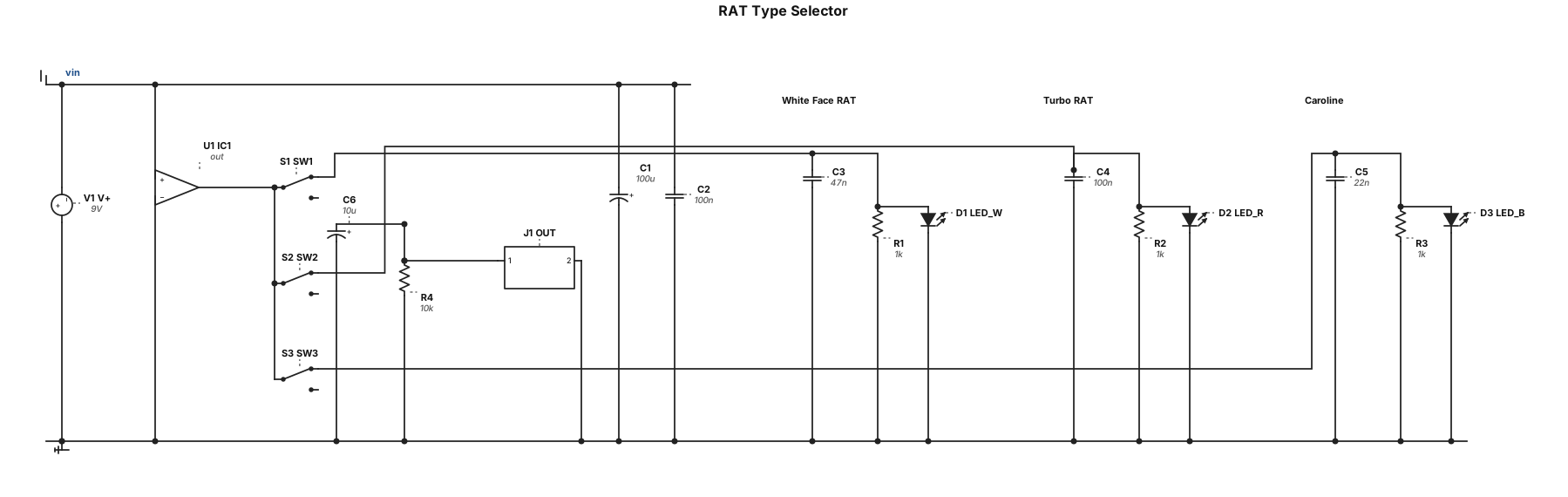
A RAT type circuit allowing to switch between the following circuits: white face RAT, Turbo Rat and Caroline. Use a rotoswitch to commute the entire circuit to the selected one. Only one ompamp. One jack output, one status led (off: shutdown, white: white face circuit, red: turbo rat circuit, blue: Caroline circuit) Add functional visuals indicators
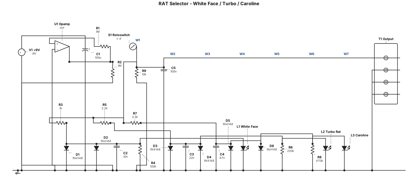
A RAT type circuit allowing to switch between the following circuits: white face RAT, Turbo Rat and Caroline. Use a rotoswitch to commute the entire circuit to the selected one. Only one ompamp. Add functional visuals indicators

A RAT type circuit allowing to switch between the following circuits: white face RAT, Turbo Rat and Caroline. Use a rotoswitch to commute the entire circuit tôt he next one. Add functional visuals indicators
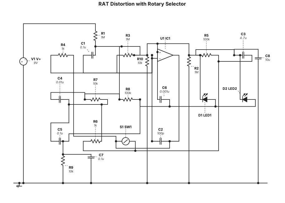
A RAT type circuit allowing to switch between the following circuits: white face RAT, Turbo Rat and Caroline. Use a rotoswitch to commute the entire circuit tôt he next one
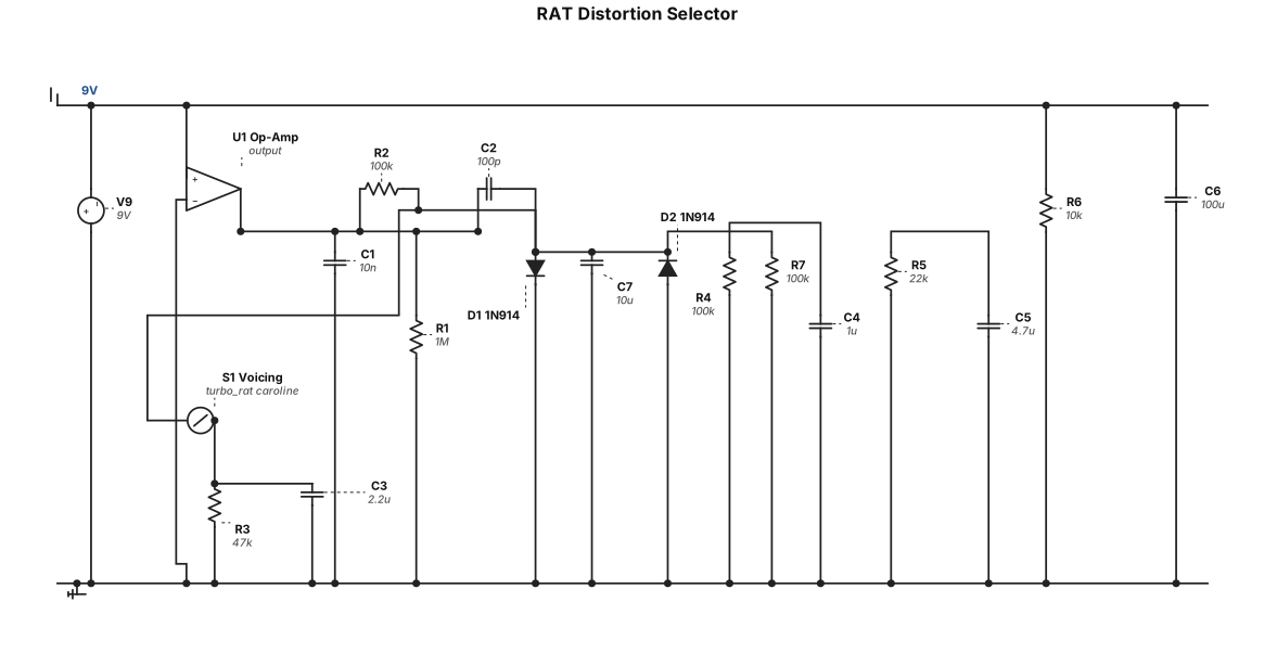
A RAT type circuit allowing to switch between the following circuits: - white face RAT - Turbo Rat - Caroline
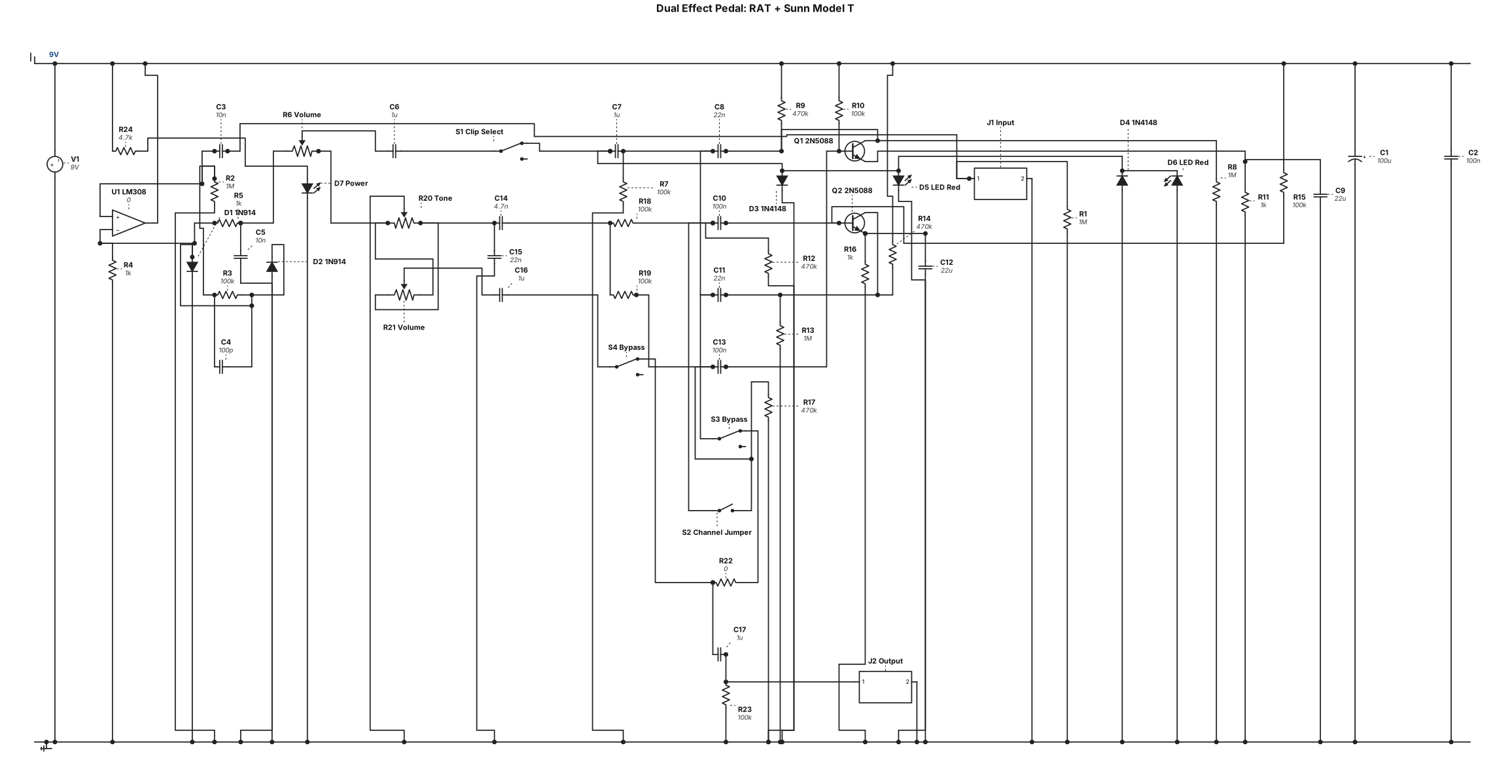
An effect pedal containing two circuits. First, a RAT type pedal, if possible with Silicon or Led type switch Second, the Sunn Models T architecture. A switch button allows to bypass it. Another one to enable the jumper between both channels.
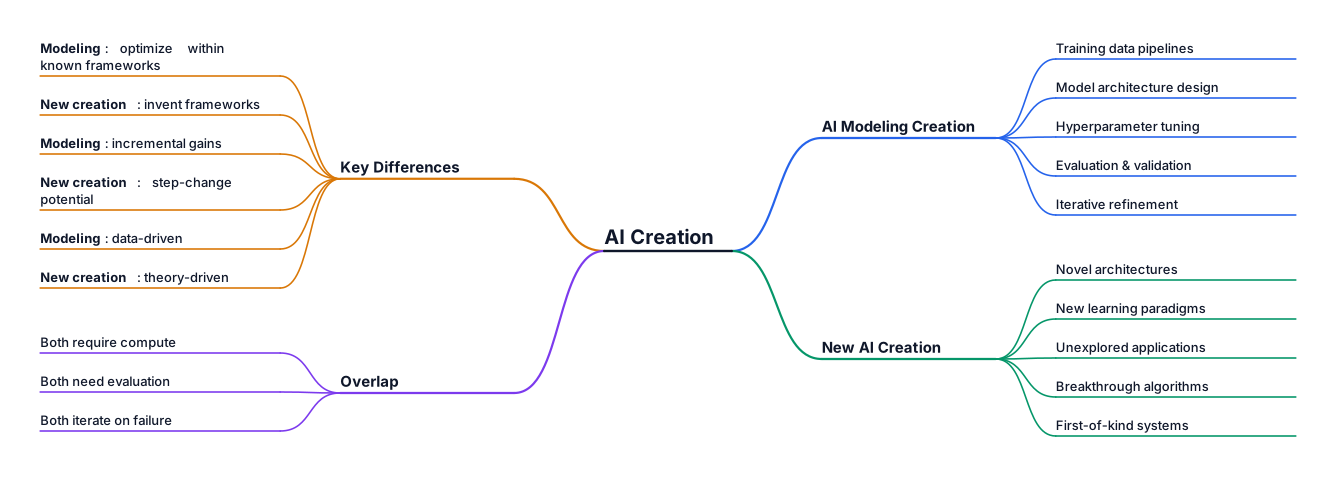
ai modeling creation vs new ai creation
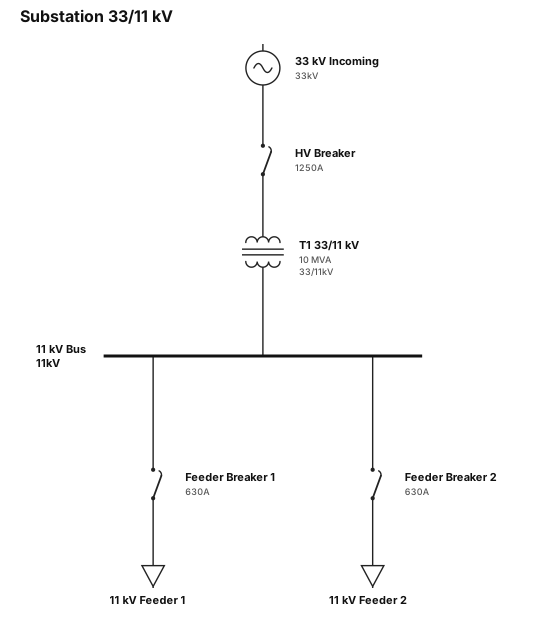
a substation 33/11 kv
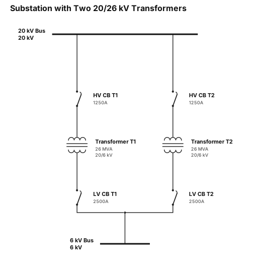
A single-line diagram for a substation with 2 20/26 transformaer
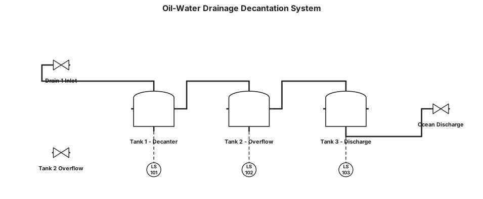
Residual oil and water through drain 1 enter tank 1. In tank 1 we have a decantation system where oil and cement residues will settle at the bottle. The water remain at the top and go to tank 2. When tank 2 overflows water go to tank 3. Then water from tank 3 go into the ocean. It is a drainage system
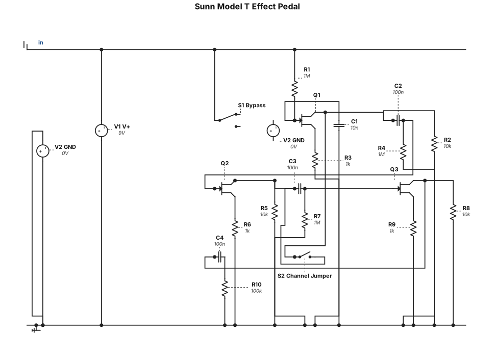
An effect pedal containing the Sunn Models T architecture. A switch button allows to bypass it. Another one to enable the jumper between both channels.
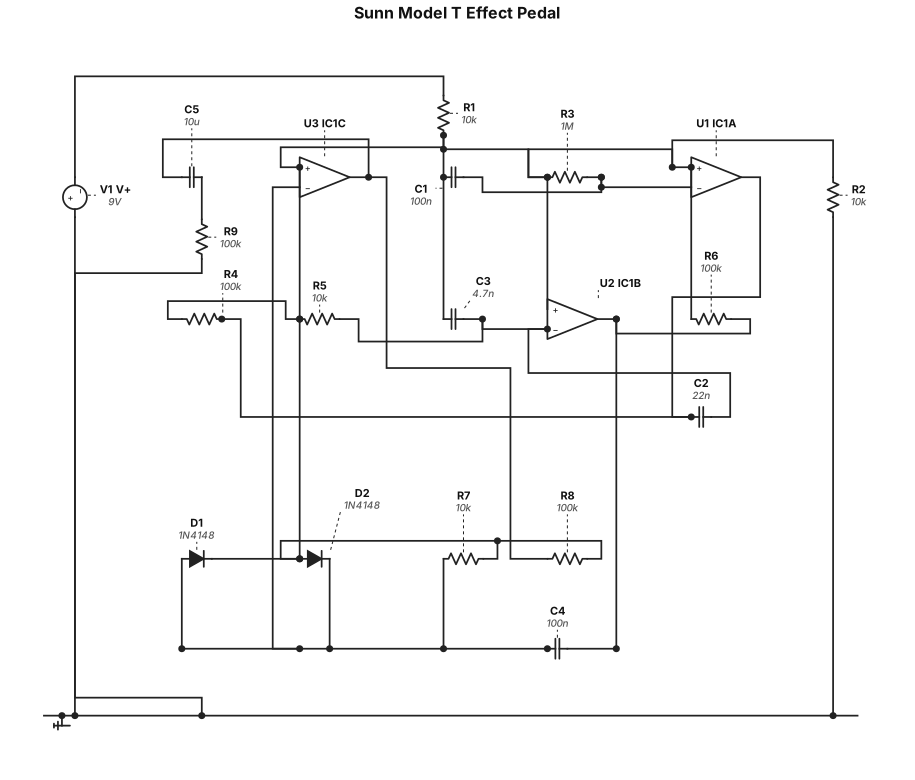
An effect pedal containing the Sunn Models T architecture
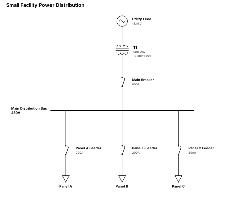
A single-line diagram for a small facility: utility feed, transformer, main breaker, and three load panels