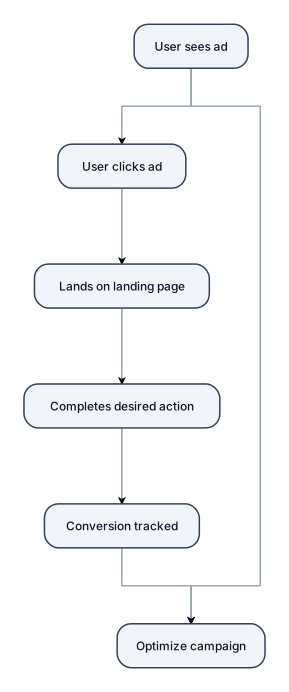
meta ad and performance marketing
NODE ARCHIVE · REAL DIAGRAM BRIEFS
Diagram Examples from Real Visitor Prompts
Browse eligible diagrams shared by FreeDiagram visitors, inspect the exact prompts, and build your own version.
Browse 3261 real creationsCOMMUNITY OUTPUTS · EXACT PROMPTS
Main diagram studio
Showing 97–120 of 1256. No stock examples or system defaults. Choose a tool, study a real result, then reopen its prompt as your starting point.
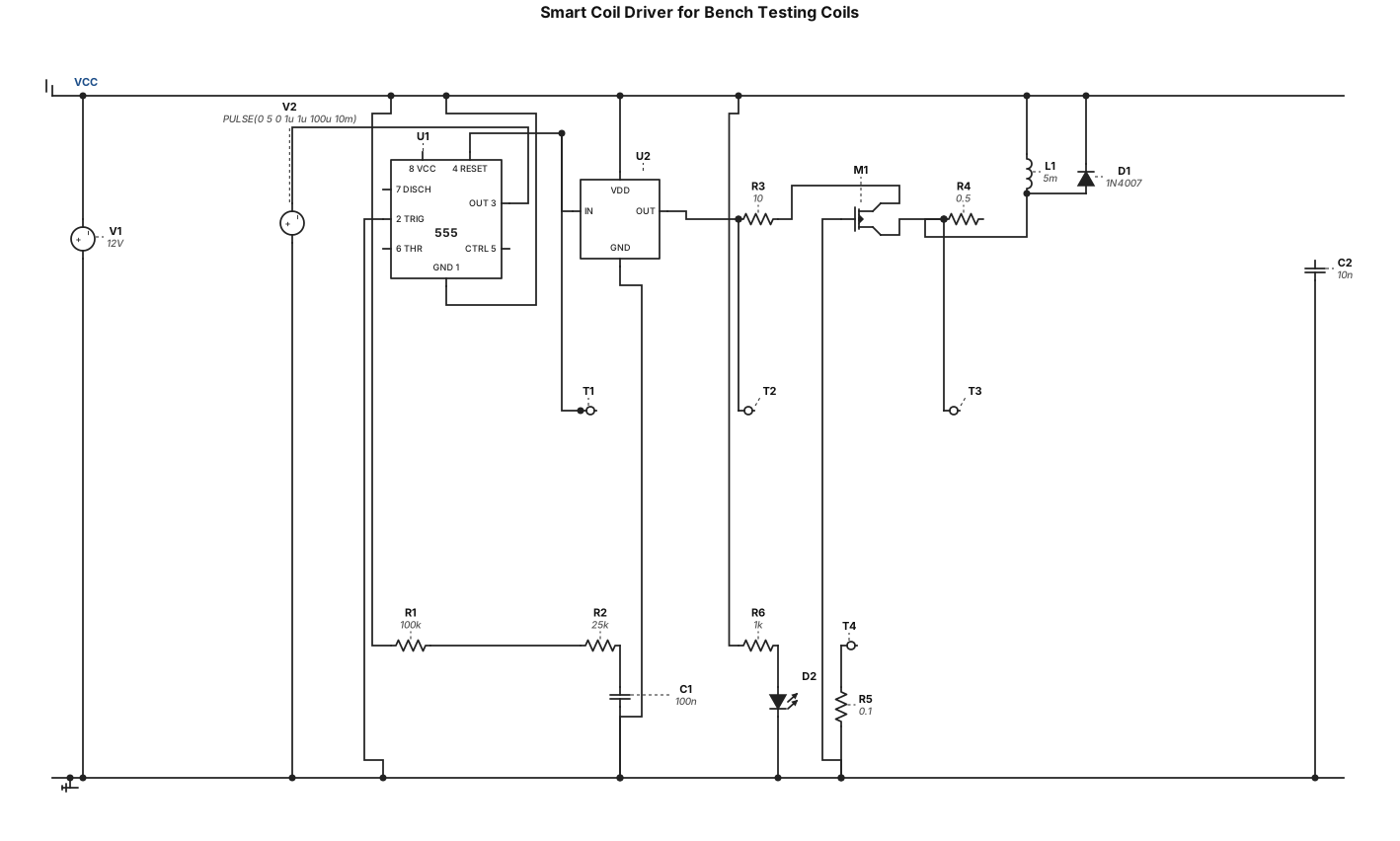
design a smart coil driver to bench test coils 2.5ms dwell . no arduino
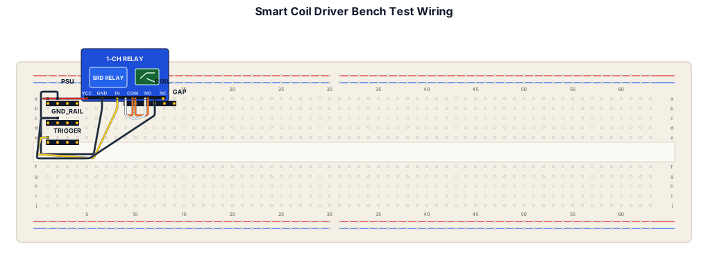
draw a wiring diagram for a smart coil driver to bench test coils

Директор, Маркетолог, Специалист по закупкам, Заведующий складом, Промышленный дизайнер, Инженер-конструктор, Специалист по электронике, Специалист по сертификации, Технолог, Оператор ТПА (термопластавтомата), Монтажник РЭА (радиоэлектронной аппаратуры), Сборщик прототипов / Сборщик-комплектовщик, Контролер ОТК, Юрист, Бухгалтер. Сделай диаграмму где важные професии верху, идут в низ к неважным
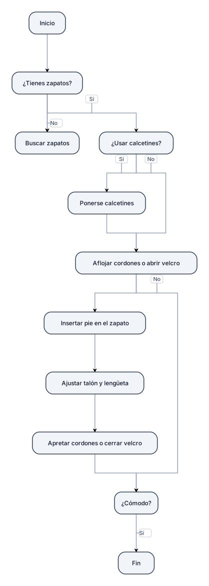
hazme un diagrama de flujo de como ponerse zapatos
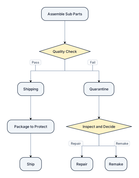
Assemble Sub parts move to Quaility, pass move to shipping, fail move to Quarantine at shipping package to protect and ship in quarantine inspect and decide to repair or remake
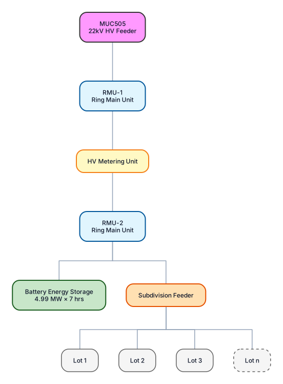
I want to draw a high level electrical SLD based on following: HV feeder MUC505 22kV Coming of this is an RMU which then connected back into the feeder. This RMU is to support an light industrial subdivision and the subdivision load is to be metered so associated with the RMU will be a HV metering unit. Out of this will be another separate RMU which will then have two load connections, 1 going to a capacity battery 4.99MW x 7hrs. The other load connection will be a feeder that suppliers the individual lots. The lot connections do not need to be shown in detail they can just be shown as branches. Show say 1 to 3 lots as an example and then draw such that implies it continues beyond 3 lots (ie. like 1, 2, 3 etc. etc. but in drawing terms). MUC needs to be a line and with two branches then feeding first RMU and HV meter before going into next RMU which then branches to capacity battery load and feeder supplying a number of subdivision lot loads with the lot loads shown as branches of that. Instead of trying to do as an SLD do as a flow chart instead. That looks good. Use same hiearchy but make it look a little more like an SLD by using some typical electrical symbols
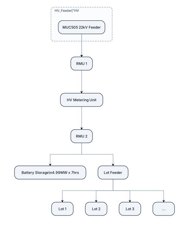
I want to draw a high level electrical SLD based on following: HV feeder MUC505 22kV Coming of this is an RMU which then connected back into the feeder. This RMU is to support an light industrial subdivision and the subdivision load is to be metered so associated with the RMU will be a HV metering unit. Out of this will be another separate RMU which will then have two load connections, 1 going to a capacity battery 4.99MW x 7hrs. The other load connection will be a feeder that suppliers the individual lots. The lot connections do not need to be shown in detail they can just be shown as branches. Show say 1 to 3 lots as an example and then draw such that implies it continues beyond 3 lots (ie. like 1, 2, 3 etc. etc. but in drawing terms). MUC needs to be a line and with two branches then feeding first RMU and HV meter before going into next RMU which then branches to capacity battery load and feeder supplying a number of subdivision lot loads with the lot loads shown as branches of that. Instead of trying to do as an SLD do as a flow chart instead

I want to draw a high level electrical SLD based on following: HV feeder MUC505 22kV Coming of this is an RMU which then connected back into the feeder. This RMU is to support an light industrial subdivision and the subdivision load is to be metered so associated with the RMU will be a HV metering unit. Out of this will be another separate RMU which will then have two load connections, 1 going to a capacity battery 4.99MW x 7hrs. The other load connection will be a feeder that suppliers the individual lots. The lot connections do not need to be shown in detail they can just be shown as branches. Show say 1 to 3 lots as an example and then draw such that implies it continues beyond 3 lots (ie. like 1, 2, 3 etc. etc. but in drawing terms). MUC needs to be a line and with two branches then feeding first RMU and HV meter before going into next RMU which then branches to capacity battery load and feeder supplying a number of subdivision lot loads with the lot loads shown as branches of that

I want to draw a high level electrical SLD based on following: HV feeder MUC505 22kV Coming of this is an RMU which then connected back into the feeder. This RMU is to support an light industrial subdivision and the subdivision load is to be metered so associated with the RMU will be a HV metering unit. Out of this will be another separate RMU which will then have two load connections, 1 going to a capacity battery 4.99MW x 7hrs. The other load connection will be a feeder that suppliers the individual lots. The lot connections do not need to be shown in detail they can just be shown as branches. Show say 1 to 3 lots as an example and then draw such that implies it continues beyond 3 lots (ie. like 1, 2, 3 etc. etc. but in drawing terms).

Create a clean, easy-to-read Amazon Rainforest Food Web for a school project. IMPORTANT DESIGN RULES: Use ONLY words, labels, and arrows. NO pictures, drawings, icons, or decorations. Use a plain white background with black text. Make the diagram neat, organized, and easy to understand. Show arrows pointing from the food to the organism that eats it, showing the direction energy travels. Arrange organisms by energy level, with producers near the bottom, consumers above them, and decomposers off to the side. Create a real food WEB with multiple connections, not just one straight food chain. INCLUDE THESE EXACT 15 ORGANISMS: ANIMALS (5): Jaguar Toucan Three-toed sloth Poison dart frog Giant river otter PLANTS (5): Brazil nut tree Rubber tree Kapok tree Cacao tree Giant water lily FUNGI (5): Bracket fungi Wood-decay mushrooms Cup fungi Mycorrhizal fungi Decomposer molds FOOD WEB CONNECTIONS: Sun → plants (show energy entering the food web). Cacao tree and Brazil nut tree → toucan, where the fruits or seeds are eaten. Suitable leaves → three-toed sloth. Insects → poison dart frog. Fish → giant river otter. Appropriate prey → jaguar. Dead plant material → wood-decay fungi, bracket fungi, cup fungi, and decomposer molds. Mycorrhizal fungi ↔ plant roots to show their mutually beneficial relationship. You may include “insects,” “fish,” “plant roots,” and “dead plant material” as small supporting labels, but do not count them as part of the 15 organisms. Do not invent feeding relationships just to connect everything. Make sure every arrow is biologically reasonable. If a connection is uncertain, leave it out. At the bottom, add a small legend: “Arrows show the direction energy moves from food to eater.”
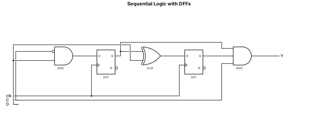
1. This circuit contains two D Flip-Flops (Q0 and Q1) triggered by the negative edge of the clock (negedge clk). 2. The D input for Q0 is the result of an AND operation between (~C) and D. 3. The D input for Q1 is the result of an XOR operation between Q0 and D. 4. The final output Y is the result of an AND operation (Q0 & Q1 & C).
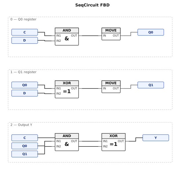
Draw the functional block diagram (fbd) of the circuit resulting from the synthesis of the following Verilog code. module SeqCircuit (clk, C, D, Y); input clk, C, D; output Y; reg 20, Q1; always @ (negedge clk) begin QO<= C & D; Q1<= (Q0D); end assign Y = (Q0 & Q1) A C; endmodule
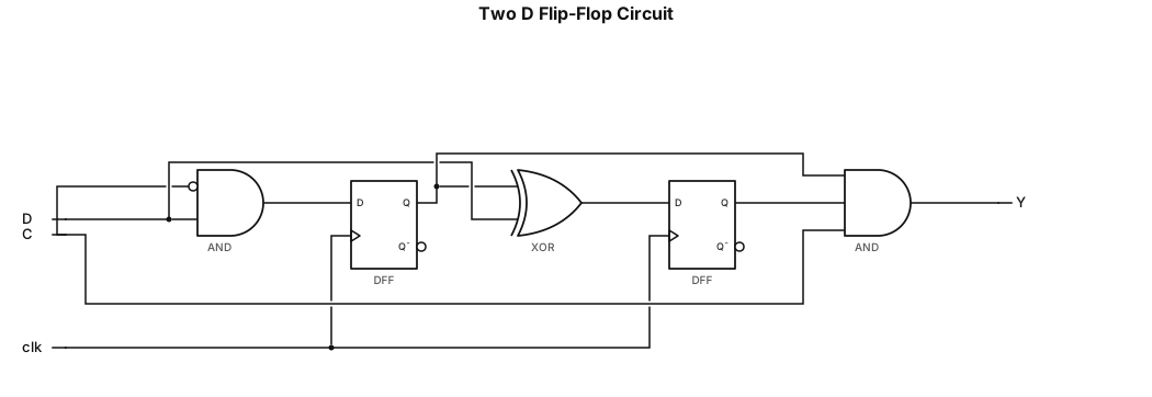
1. This circuit has two D Flip-Flops (Q0 and Q1) triggered by the negative edge of the clock (negedge clk). 2. Input D for Q0 is the result of an AND gate between (~C) and D. 3. Input D for Q1 is the result of an XOR gate between QO and D.. 4. The final output Y is the result of the AND gate (Q0 & Q1 & C).

Crea un mapa conceptual en español titulado “Historia de Santo Domingo”. Organízalo con seis temas principales: La llegada de los esclavizados, Los tratados, La Era Francesa, La España Boba, La Independencia Efímera y La sociedad taína. Para cada tema, incluye fechas importantes, causas, características, personajes y consecuencias cuando correspondan. Utiliza cuadros, flechas, colores diferentes y palabras clave. Organiza la información de forma clara, con ideas principales y secundarias, sin párrafos largos. El mapa debe ser fácil de leer, estudiar y presentar en la escuela. Usa un diseño horizontal y permite descargarlo como imagen o PDF.
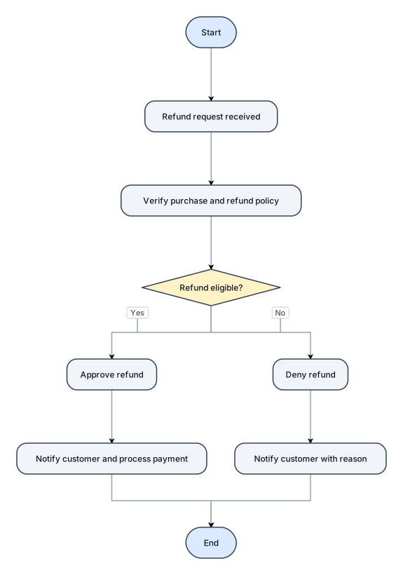
A flowchart for handling a customer refund request, with approve and deny paths
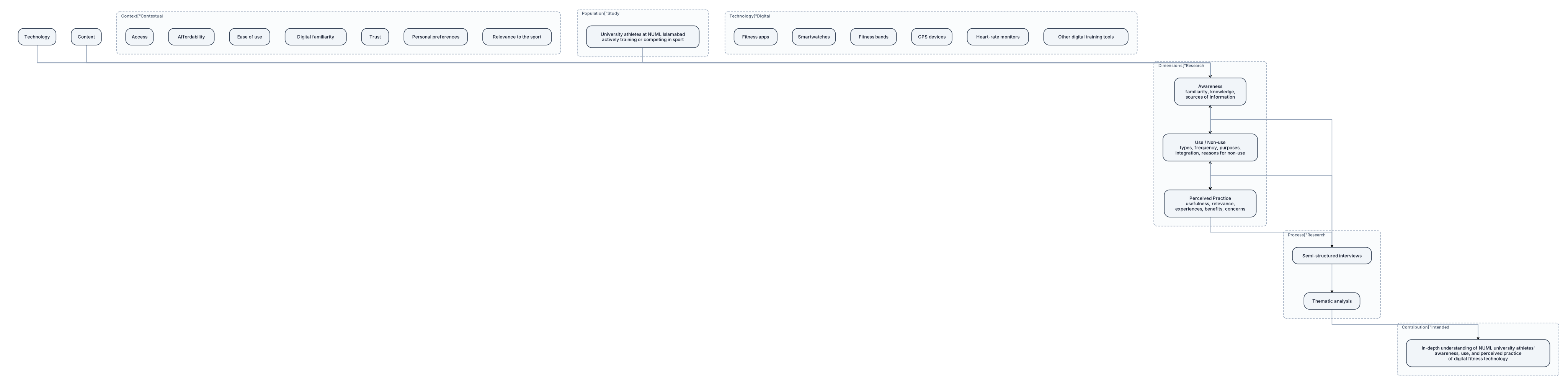
Create a professional academic conceptual framework diagram for the research titled “Awareness, Use, and Perceived Practice of Digital Fitness Technology for Training Among University Athletes”. Study population: enrolled NUML Islamabad students who actively train or compete in a sport. Show the following structure: 1. **Study Population:** University athletes at NUML Islamabad. 2. **Digital Fitness Technology:** Fitness apps, smartwatches, fitness bands, GPS devices, heart-rate monitors, and other digital training tools. 3. **Three interconnected research dimensions:** - Awareness: familiarity, knowledge, and sources of information. - Use / Non-use: types of technology, frequency, purposes, integration into training, and reasons for non-use. - Perceived Practice: perceived usefulness, relevance to training, experiences, benefits, and concerns. 4. **Contextual factors:** Access, affordability, ease of use, digital familiarity, trust, personal preferences, and relevance to the sport. 5. **Research process:** Semi-structured interviews followed by thematic analysis. 6. **Intended contribution:** An in-depth understanding of NUML university athletes’ awareness, use, and perceived practice of digital fitness technology. Use labelled boxes, clean arrows, a balanced layout, restrained academic colours, and readable typography. Show that the three research dimensions are interconnected, not independent and dependent variables in a causal model. Do not imply that technology necessarily improves athletic performance. Make the diagram suitable for insertion into a university research proposal.
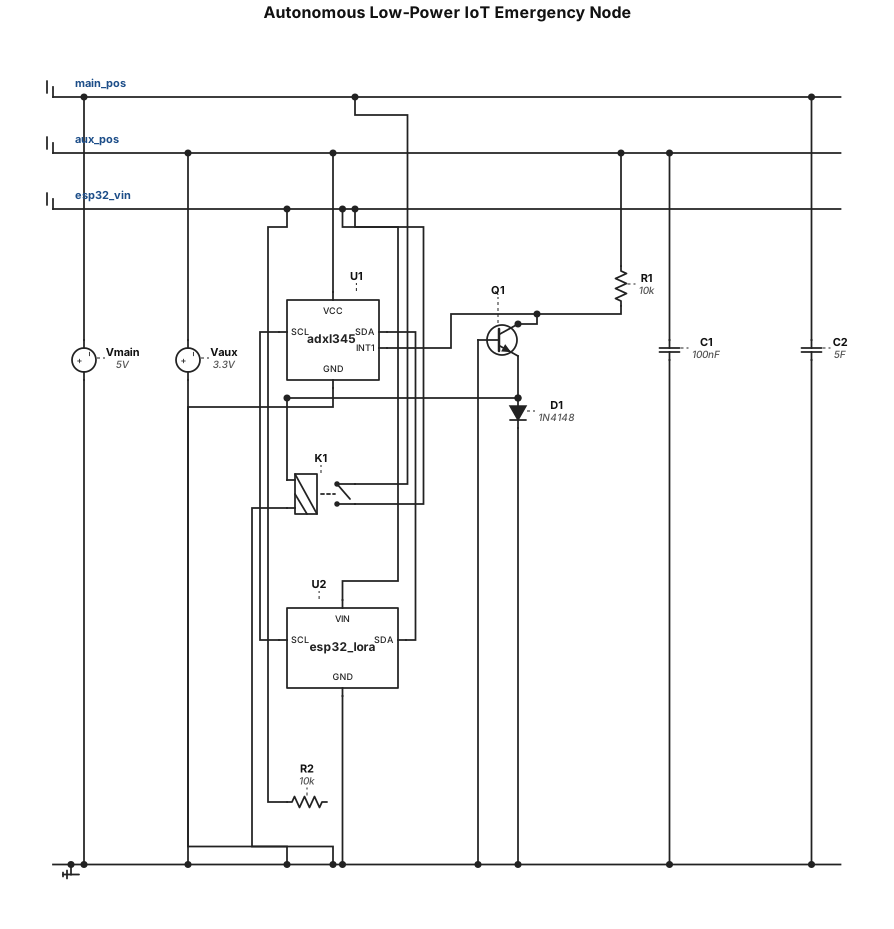
Design an electronic schematic for an autonomous low-power IoT emergency node with two power domains. It must include the following components and connections: Microcontroller & Radio: An ESP32 module with integrated LoRa transceiver (such as a Heltec/LilyGO board). Sensor: An I2C triaxial accelerometer (such as ADXL345) connected to the ESP32's I2C pins (SDA, SCL) and powered by a low-power auxiliary line. The accelerometer's hardware interrupt pin (INT1) must be routed to trigger the power switch circuit. Power Switching: A latching relay (biestable relay) acting as a master power gate. Power Domains: A primary auxiliary battery line for continuous low-power monitoring of the sensor, and an isolated main power line (supercapacitor / high-energy source) connected through the latching relay that feeds the ESP32 LoRa module only when triggered by the sensor's hardware interrupt. Please generate the schematic layout and component connections based on these industrial low-power requirements.

Sujet 1 : Les déterminants sociaux de la santé et des maladies : le cas de la tuberculose et de la diphtérie au Maroc Fais moi une présentation de ce sujet

Sujet 1 : Les déterminants sociaux de la santé et des maladies : le cas de la tuberculose et de la diphtérie au Maroc Fais moi une représentation concernant ce sujet avec une introduction générale et des axes
Кнопка с фиксацией от 220в к свето звуковому зуммеру
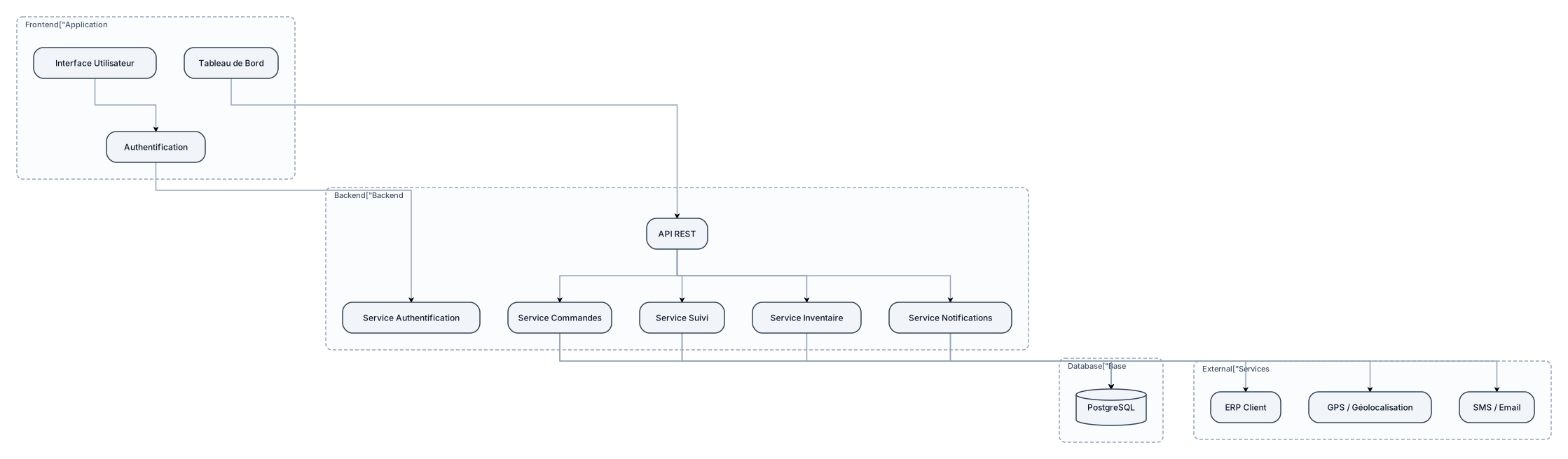
CREAT UN DIGRAME POUR UN APPLICATION SUIVI LOGISTIQUE
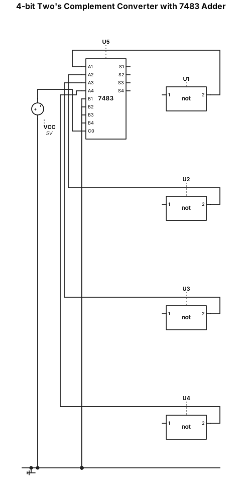
Create a detailed schematic of a 4-bit Two's Complement converter with a 7483 4-bit adder chip: Inputs A0, A1, A2, A3 pass through four NOT gates to invert all bits. The outputs of the NOT gates connect to inputs A1, A2, A3, A4 of the 7483 adder. Inputs B1, B2, B3, B4 of the 7483 are tied to GND (0). Carry-in (C0 or Cin) is tied to VCC (1) to add the +1 required for Two's Complement. Outputs S1, S2, S3, S4 show the final 4-bit Two's Complement result.
"Generate a logic circuit diagram for a 4-bit Two's Complement generator using a 7483 4-bit binary adder chip. The 4-bit input (A0-A3) goes through 4 NOT gates (inverters) into the A inputs of the 7483 adder. The B inputs (B0-B3) of the 7483 are connected to GND (logic 0). The Carry In (Cin) pin is connected to VCC (logic 1) to add 1. Show outputs S0-S3 and Carry Out (Cout)."