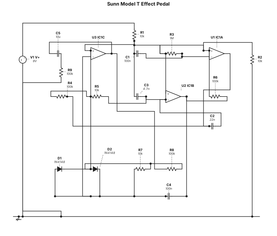
An effect pedal containing the Sunn Models T architecture
NODE ARCHIVE · REAL DIAGRAM BRIEFS
Diagram Examples from Real Visitor Prompts
Browse eligible diagrams shared by FreeDiagram visitors, inspect the exact prompts, and build your own version.
Browse 3261 real creationsCOMMUNITY OUTPUTS · EXACT PROMPTS
Circuit Diagrams
Showing 97–120 of 270. No stock examples or system defaults. Choose a tool, study a real result, then reopen its prompt as your starting point.
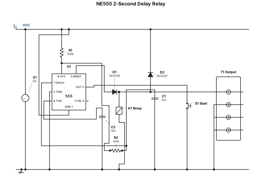
5V NE555 timer, 2 second delay, relay output, show all pin numbers.”
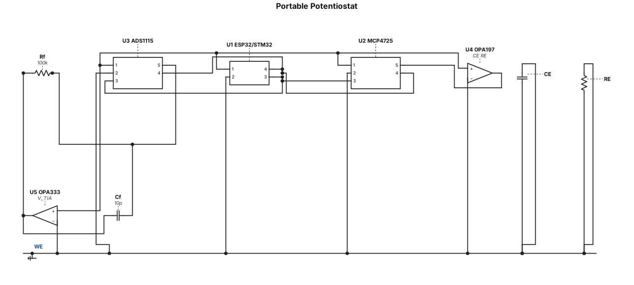
Portable Potentiostat +3.3 V / +5 V │ ┌───────▼────────┐ │ Microcontroller │ │ ESP32 / STM32 │ └───────┬────────┘ │ I²C ┌──────────┴───────────┐ │ │ ┌──────▼──────┐ ┌──────▼──────┐ │ DAC MCP4725 │ │ ADC ADS1115 │ │ Set voltage │ │ Measurement │ └──────┬──────┘ └──────▲──────┘ │ │ VSET / VREF │ │ │ ┌─────▼─────────────┐ │ │ Control Op-Amp │ │ │ OPA197 / OPA192 │ │ │ │ │ RE ─────► (+/− feedback) │ │ │ │ │ └─────┬─────────────┘ │ │ │ ▼ │ CE │ │ │ │ Electrochemical │ │ Cell │ │ │ RE WE │ ┌───────▼────────┐ │ Transimpedance │ │ Amplifier TIA │ │ OPA333/OPA388 │ └───────┬────────┘ │ V_TIA │ └────────► ADS1115
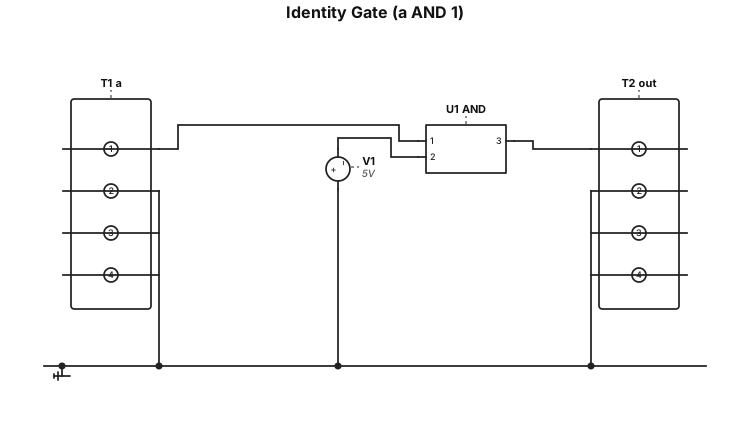
Give me a circuit diagram for a circuit that has 2 input lines (a and b) and one output line and the output line = 1 if and only if a = 1 (use AND, OR, and NOT gates)
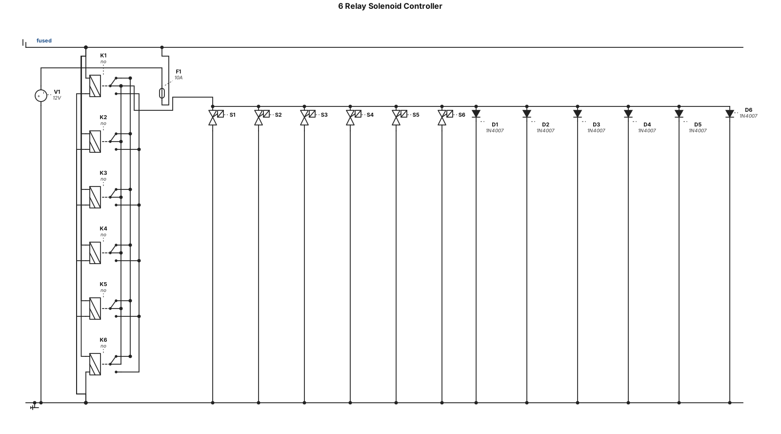
6 12v relays controlling solenoids
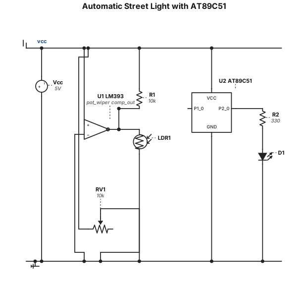
“Create an Automatic Street Light circuit using AT89C51 8051, LDR, 10k resistor, LM393 comparator, 10k potentiometer, LED and 330 ohm resistor. LDR voltage divider output goes to LM393 positive input. Potentiometer wiper goes to negative input. LM393 output goes to P1.0. P2.0 drives LED through 330 ohm resistor. Show +5V and GND connections and clearly label every pin.”
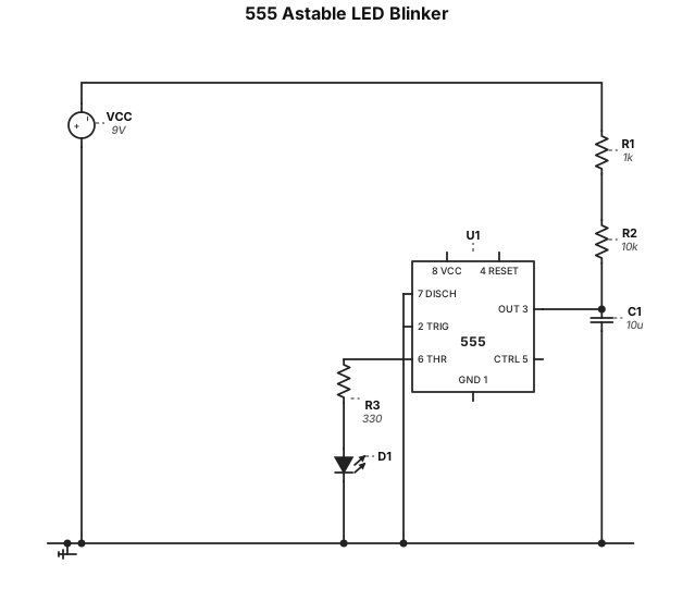
astable multivibrator 555 timer led blinking
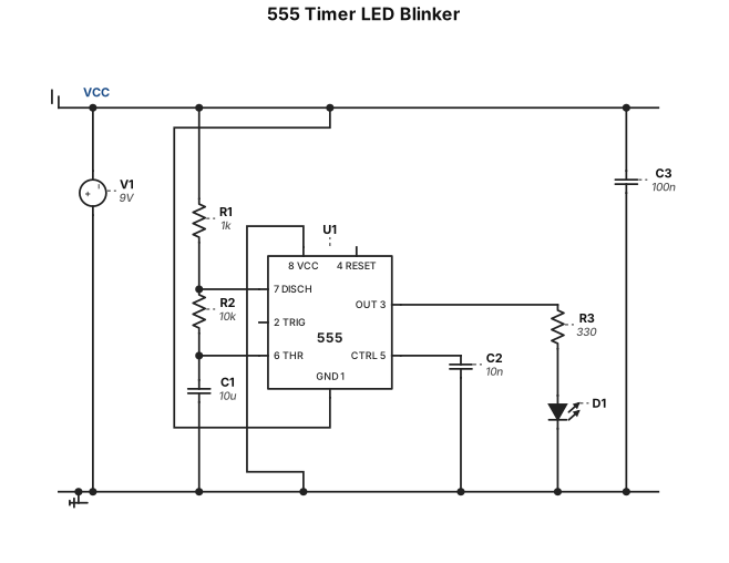
astable multivibraator 555 timer lrd blinking
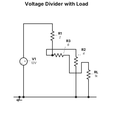
For the purposes of this question, use the following unambiguous circuit description: An ideal 12 V DC voltage source has its negative terminal connected to ground. Its positive terminal connects through a 2 Ω resistor to node A. A 4 Ω resistor connects node A to ground. A 6 Ω resistor connects node A to output node B. The load resistor R L connects node B to ground.
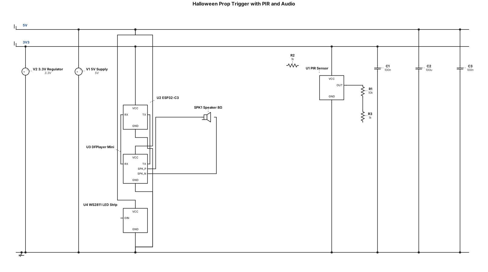
create a halloween prop trigger that uses a pir detector. When movement detected it should trigger a sound and light effect. Audio can be played from a dfplayer mini and you should use an esp32-c3. When the sound plays, some ws2811 leds shoud change from a red flowing mode to a white strobscope during playback.
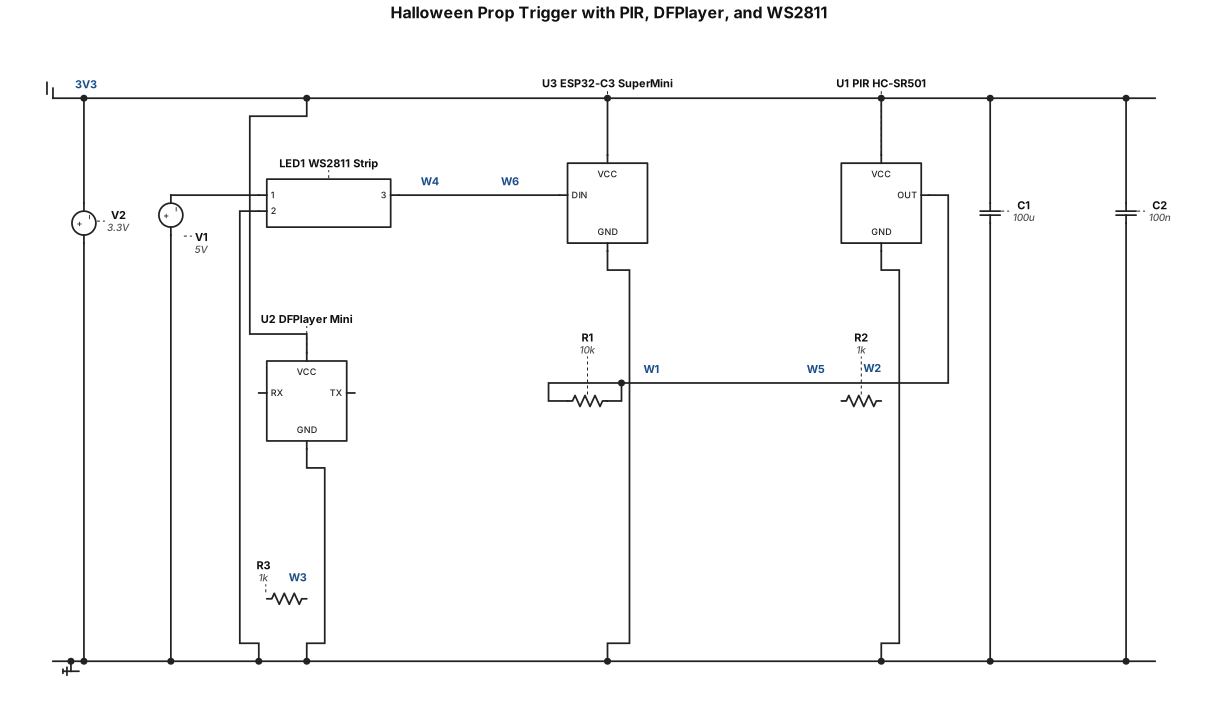
create a halloween prop trigger that uses a pir detector. When movement detected it should trigger a sound and light effect. Audio can be played from a dfplayer mini and you should use an esp32-c3-supermini. When the sound plays, some ws2811 leds shoud change from a red flowing mode to a white strobscope during playback.
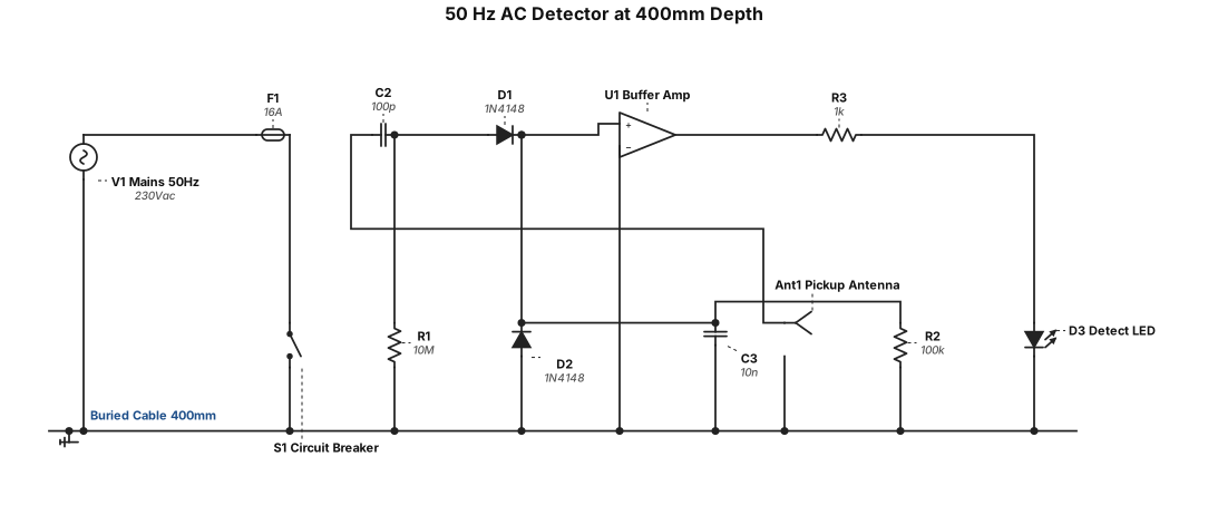
50 Hz AC detector at depth 400mm cable active no load
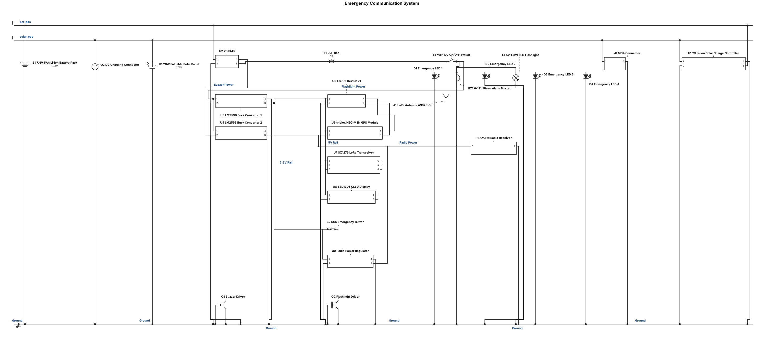
Power Management Subsystem Connect the 20 W external foldable solar panel to the MC4 connector pair, which wires into the panel-mount DC charging connector. Route the DC charging connector to the inputs of the 2S Li-ion solar charge controller. Connect the charge controller's battery terminals to the 7.4 V, 5 Ah Li-ion battery pack, which includes a 2S Battery Management System (BMS). Wire the battery's positive output in series with a DC fuse and the main DC ON/OFF switch. Distribute the switched battery power to the inputs of two LM2596 adjustable DC-DC step-down buck converters. These buck converters will provide the required regulated voltage for electronic components that cannot be directly supplied by the 7.4 V battery. Microcontroller and Data Connections Place the ESP32 DevKit V1 (3.3 V logic) as the central controller of the system. GPS Module: Connect the u-blox NEO-M8N module to the ESP32 using a UART/Serial interface. LoRa Transceiver: Connect the AS923-3-compatible SX1276-class LoRa module to the ESP32 using an SPI interface. Attach the frequency-compatible LoRa antenna to the transceiver using an external/SMA cable. OLED Display: Connect the 0.96-inch SSD1306 OLED display to the ESP32 using an I²C interface. Emergency Interfaces and Alerts SOS Button: Connect the momentary emergency push button to a designated digital input pin on the ESP32. Visual Indicators: Connect the four emergency LED indicator lights to ESP32 digital output pins. Alarm Buzzer: Wire the ESP32 control signal to the 6-12 VDC high-output piezo alarm buzzer. Flashlight: Connect the 5 V DC, 1-3 W compact LED flashlight to an appropriate switching or driver circuit controlled by the ESP32. AM/FM Radio: Wire the portable AM/FM radio receiver to the required regulated power line; this component operates as an independent emergency information function managed by its own tuning/volume knob.
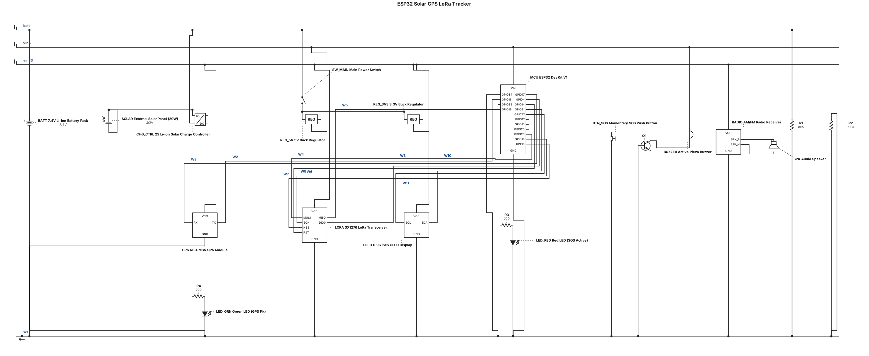
1. Main Controller Node ID: MCU Label: "ESP32 DevKit V1" 2. Power Management Subsystem Nodes: SOLAR: "External Solar Panel (20W)" CHG_CTRL: "2S Li-ion Solar Charge Controller (8.4V)" BATT: "7.4V Li-ion Battery Pack (with BMS)" SW_MAIN: "Main Power Switch (SPST)" REG_5V: "5V Buck Regulator" REG_3V3: "3.3V Buck Regulator" Power Connections: SOLAR connects to CHG_CTRL Input CHG_CTRL Output connects to BATT BATT connects to SW_MAIN SW_MAIN Output splits to REG_5V Input, REG_3V3 Input, and a "7.4V Rail" REG_5V Output connects to MCU "VIN" pin REG_3V3 Output connects to "3.3V Rail" (to power sensors) BATT (via voltage divider) connects to MCU analog pin (GPIO34) for "Battery Monitoring" 3. GPS Location Subsystem Node ID: GPS Label: "NEO-M8N GPS Module + Patch Antenna" Connections: Connect to 3.3V Rail and GND UART Data: GPS TX connects to MCU RX2 (GPIO16); GPS RX connects to MCU TX2 (GPIO17) 4. LoRa Communication Subsystem Node ID: LORA Label: "SX1276 LoRa Transceiver (AS923) + Antenna" Connections: Connect to 3.3V Rail and GND SPI Interface: Connect to MCU standard SPI pins (MOSI, MISO, SCK, CS/NSS) Control Lines: Connect LORA DIO0 and RST pins to MCU GPIOs (GPIO4 and GPIO14 respectively) 5. Display & Indicators Nodes: OLED: "0.96 inch OLED Display (SSD1306)" LED_RED: "Red LED (SOS Active)" LED_GRN: "Green LED (GPS Fix)" Connections: OLED: Connect to 3.3V Rail. I2C Data: SDA to MCU GPIO21, SCL to MCU GPIO22. LEDs: Connect to MCU GPIOs (GPIO12 and GPIO13) via current-limiting resistors to GND. 6. Inputs & Audio Subsystem Nodes: BTN_SOS: "Momentary SOS Push Button" BUZZER: "Active Piezo Buzzer" RADIO: "Independent AM/FM Radio Receiver" SPK: "Audio Speaker" Connections: BTN_SOS: Connect between MCU GPIO35 and GND (Internal pull-up enabled). BUZZER: Connect to MCU GPIO25 (via transistor driver circuit if needed) and 5V Rail/GND. RADIO: Powered by 3.3V Rail. Audio output connected to SPK. No microcontroller data connection required.
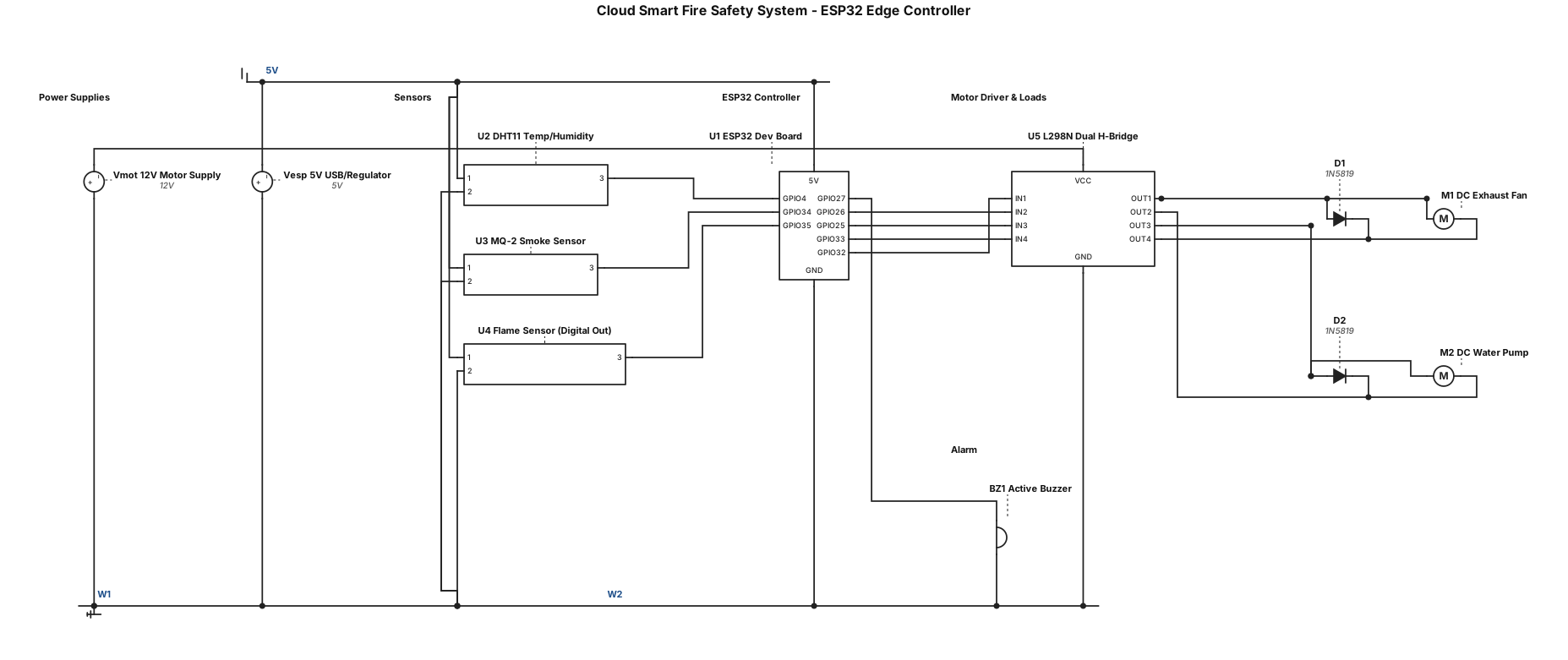
Create a detailed electrical schematic for a Cloud Smart Fire Safety System using an ESP32 development board as the main edge controller. Include an MQ-2 smoke sensor, flame sensor, DHT11 temperature and humidity sensor, buzzer, L298N motor driver, DC exhaust fan, and DC water pump. Show all power, ground, signal, and GPIO connections clearly. The ESP32 reads the MQ-2, flame sensor, and DHT11. The ESP32 controls the buzzer directly through a suitable GPIO and controls the exhaust fan and water pump through the L298N motor driver. Use an external power supply for the motor loads and clearly show the common ground between the ESP32 and motor driver. Label every component and GPIO pin. Do not connect motors directly to ESP32 GPIO pins. Add flyback protection if required. The schematic should be technically realistic and suitable for a college project report.
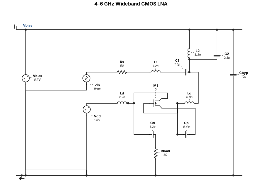
Create a clean professional CMOS RF schematic for a 4–6 GHz wideband low-noise amplifier. Use standard analog IC schematic symbols and clearly label every component and node. The input is a 50-ohm source Vin with source resistance Rs. From the input, place a series inductor L1 followed by a series capacitor C1. After C1, create matching node A. From node A to an AC-grounded bias node \(V_{bias}\), connect a parallel resonator consisting of L2 in parallel with C2. From node A, continue through a series gate inductor Lg to the gate of NMOS transistor M1. M1 is the common-source input transistor. Show an additional capacitor Cp connected between the gate and source
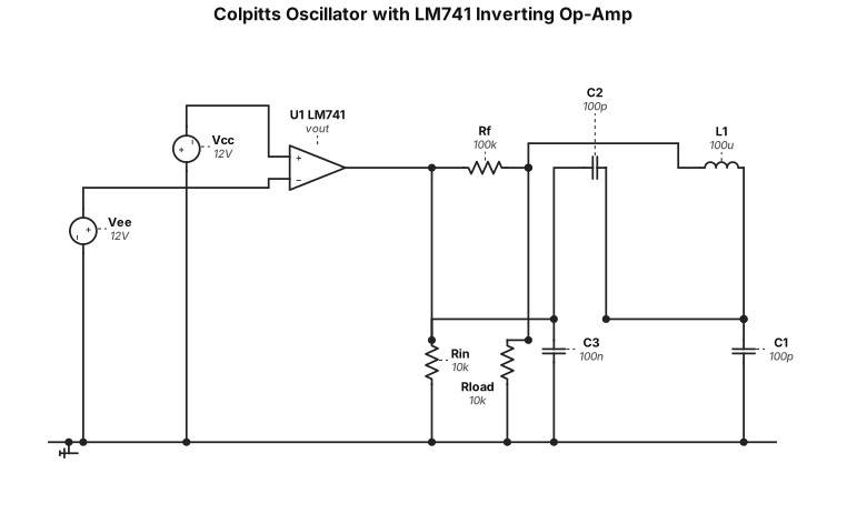
Build a Colpits oscillator using LM741 Inverting op-amp
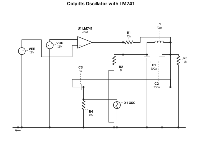
Build a Colpits oscillator using LM741 Inverting op-amp, with an inductor L, resistors and capacitors as shown in my circuit. Generate the complete schematic and simulate the output on an oscilloscope.
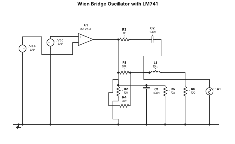
Build a Wien bridge oscillator using LM741 op-amp, with an inductor L, resistors and capacitors as shown in my circuit. Generate the complete schematic and simulate the output on an oscilloscope.
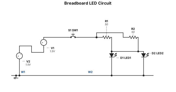
ブレッドボード上の回路 LED 赤 2 抵抗 50Ω 2 並列で接続 プッシュスイッチでON OFF バッテリー 1.5V 2 直列つなぎ バッテリーの配線図を直線で
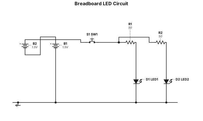
ブレッドボード上の回路 LED 赤 2 抵抗 50Ω 2 並列で接続 プッシュスイッチでON OFF バッテリー 1.5V 2 直列つなぎ
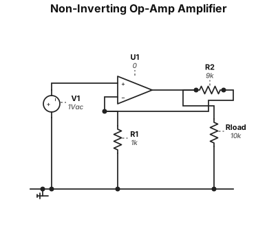
A non-inverting op-amp amplifier circuit with a gain of 10, using a 1 kΩ input resistor and a 9 kΩ feedback resistor
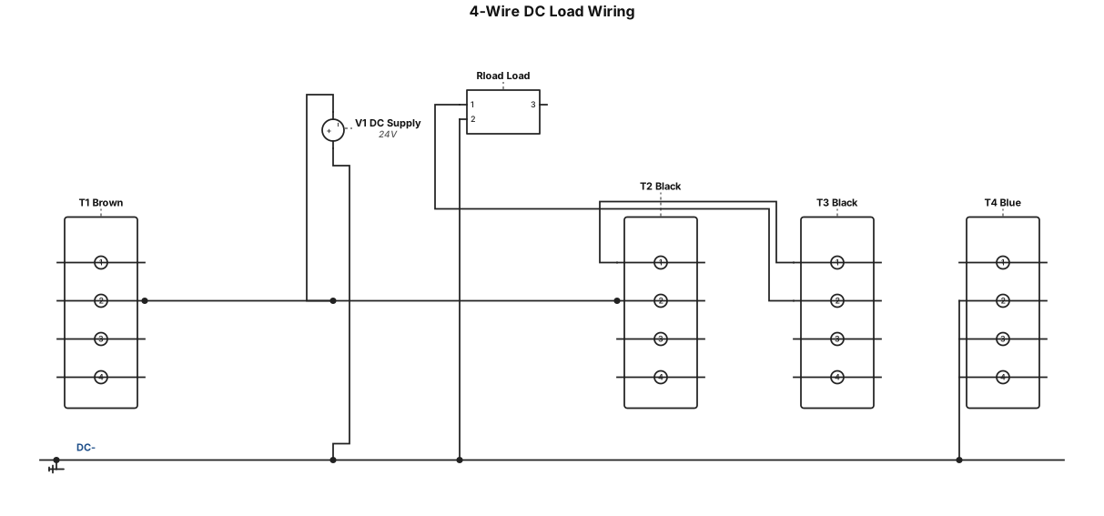
a wiring diagram that has 4 wires. Brown and Black goes to DC+, Black goes to Load and Blue goes to DC-
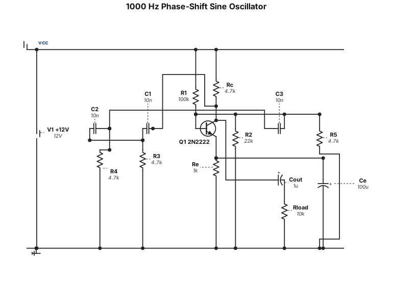
Bir tane transistörlü direnç ve kapasitör kullanan faz kaydırmalı 1000hz sinüs sinyal jeneratörü şeması çiz. Güzel çizmişsin yalnız bu şemada hatalar ve yanlışlar var onları düzelt Bu devre Bu haliyle çalışmaz şemayı tekrar gözden geçir düzenle