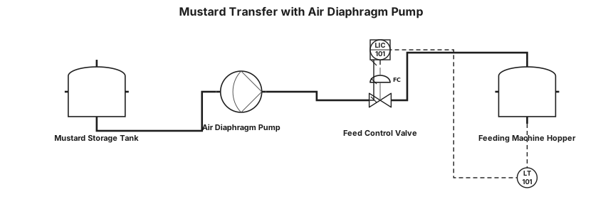
The air diaphragm pump for a mustard. From a tank 2000 liter to smaller feeding machine 200 liter that feeds the bottles on a conveyor belt
NODE ARCHIVE · REAL DIAGRAM BRIEFS
Diagram Examples from Real Visitor Prompts
Browse eligible diagrams shared by FreeDiagram visitors, inspect the exact prompts, and build your own version.
Browse 3261 real creationsCOMMUNITY OUTPUTS · EXACT PROMPTS
Pid
Showing 97–120 of 142. No stock examples or system defaults. Choose a tool, study a real result, then reopen its prompt as your starting point.
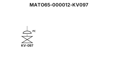
MATO65-000012-KV097
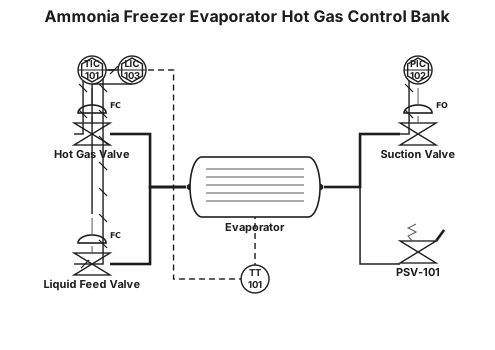
ammonia freezer evaporator hot gas control bank
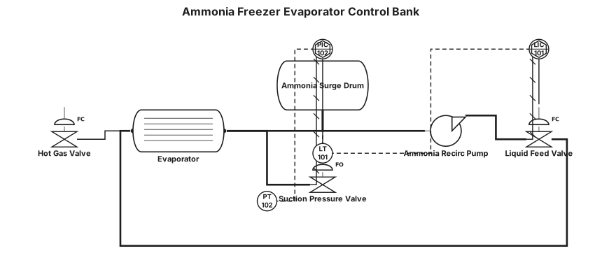
A P&ID for a ammonia freezer evaporator control bank
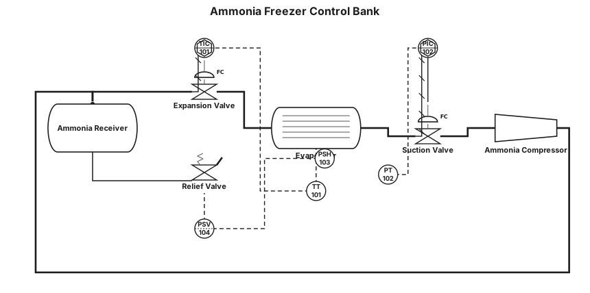
A P&ID for a ammonia freezer control bank
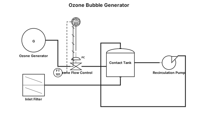
ozone boble generator
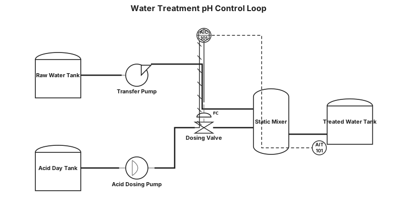
Water treatment loop with pH control and dosing pump

Trois cuves en entrée, une termostatée à 40°C qui cintient le produit (jeune) pour passage travers 3 E-PAK en série puis filtration, deux collectes séparée et évaoprées dans deux évapo collecte de deux produit un blanc et un jaune foncé, solvant sorti d'évaop recylés
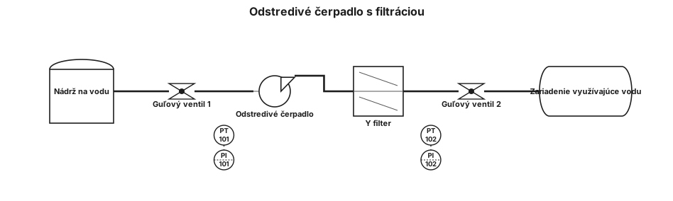
Diagram pre odstredivé čerpadlo ktoré berie vodu z nádrže 1. guľový ventil 2. snímač tlaku 3. manometer 4. čerpadlo 5. Y filter na výtlaku 6. guľový ventil 7. snímač tlaku 8. manometer 9. zariadenie čo využíva vodu
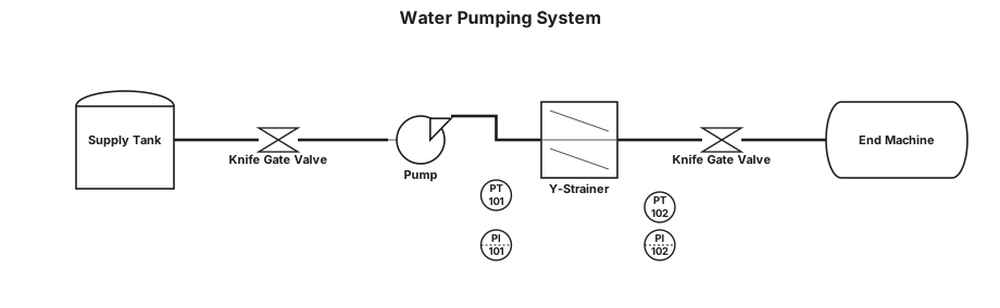
Water pumping from a tank trough Tank Knife Gate Valve Pressure Transmitter / Pressure Gauge Pump Y-Strainer Knife Gate Valve Pressure Transmitter Pressure Gauge End machine ( destination )
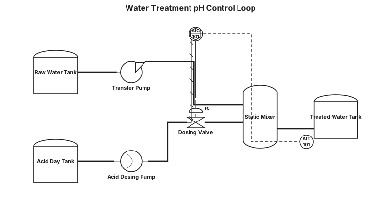
Water treatment loop with pH control and dosing pump
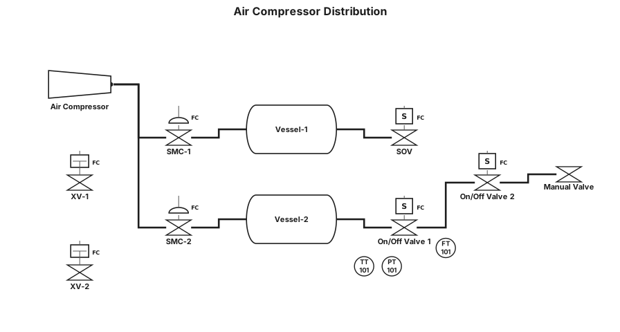
AIR COMPRESSOR 20–25 bar | +------+------+ | | SMC-1 SMC-2 Self-Reg. Self-Reg. Valve Valve | | VESSEL-1 VESSEL-2 0–17 bar 0–5.5 bar(g) | | | | LINE B LINE A | | SOV TT | | 0–15 bar PT 100 cycles | | ON/OFF VALVE 1 Pulsating Air | FT | ON/OFF VALVE 2 | MANUAL VALVE | PROCESS VESSEL-2 | LINE C | INSTRUMENT AIR / \ ↓ ↓ Actuator Actuator XV-1 XV-2
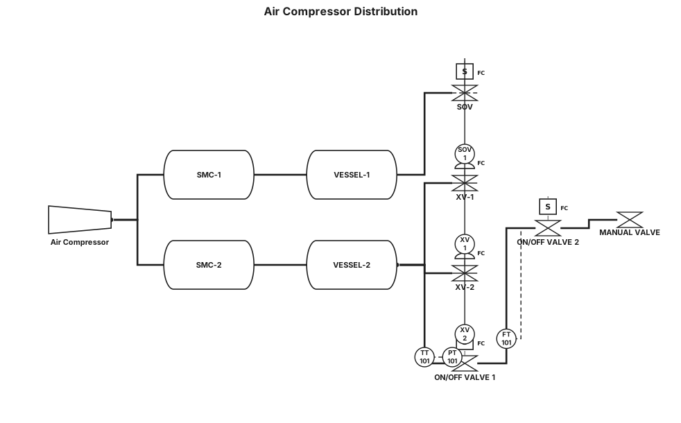
AIR COMPRESSOR 20–25 bar | +---------+---------+ | | SMC-1 SMC-2 | | ↓ ↓ ┌───────────┐ ┌───────────┐ │ VESSEL-1 │ │ VESSEL-2 │ │ 0–17 bar │ │0–5.5 barg │ └─────┬─────┘ └─────┬─────┘ | | LINE B LINE A | | SOV TT | | 0–15 bar, 100 PT cycles | | ON/OFF VALVE 1 Pulsating air | FT | ON/OFF VALVE 2 | MANUAL VALVE | PROCESS VESSEL-2 | LINE C | INSTRUMENT AIR / \ ↓ ↓ Actuator Actuator XV-1 XV-2
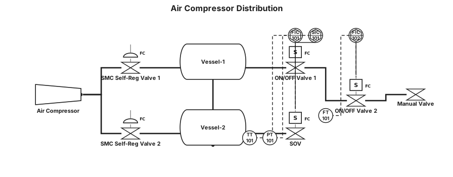
AIR COMPRESSOR 20–25 bar | +----------+----------+ | | SMC SELF-REG. SMC SELF-REG. VALVE VALVE | | VESSEL-1 VESSEL-2 0–17 bar 0–5.5 bar(g) | | LINE A | TT | PT | ON/OFF VALVE 1 | FT | ON/OFF VALVE 2 | MANUAL VALVE | PROCESS Vessel-2 ─────────────── LINE C ───────────> Instrument Air | +--> ON/OFF Valve 1 | +--> ON/OFF Valve 2 Vessel-2 ─────────────── LINE B ── SOV ────> Pulsating Air 0–15 bar 100 cycles
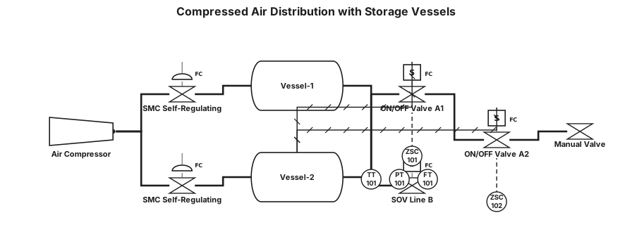
Air compressor delivers compressed air at 20–25 bar to two storage vessels using 2 SMC self-regulating valves. Vessel-1 holds air at 0–17 bar and vessel-2 holds air at 0–5.5 bar(g). A total of 3 process connections (A, B, C) are made from the two pressure vessels. Process line A is connected to vessel-2, where this line's temperature is 28°C and mass flow rate is 0.0055 kg/sec; this line contains 1 temperature transmitter, 1 pressure transmitter, 2 ON/OFF valves, 1 flow transmitter and 1 manual valve. For line A, calculate the volumetric flow in m³/hr (given gas constant). Line B uses a SOV and provides pulsating pressure of 100 cycles at 0–15 bar, whereas line C acts as instrument air to the automatic ON/OFF valves mounted on process line A. Draw the P&ID diagram for all the process connections, pressure vessels and instrumentation.A control valve regulates process flow. Maximum differential pressure: ΔP = 1.5 bar (take SG = 1).
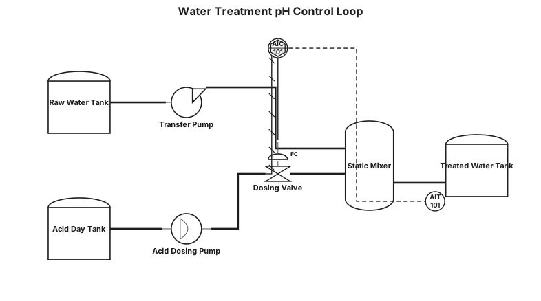
Water treatment loop with pH control and dosing pump
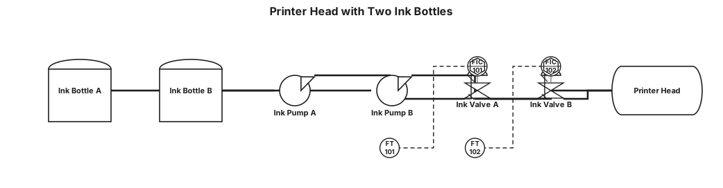
PRINTER HEAD WITH TWO INK BOTTLE
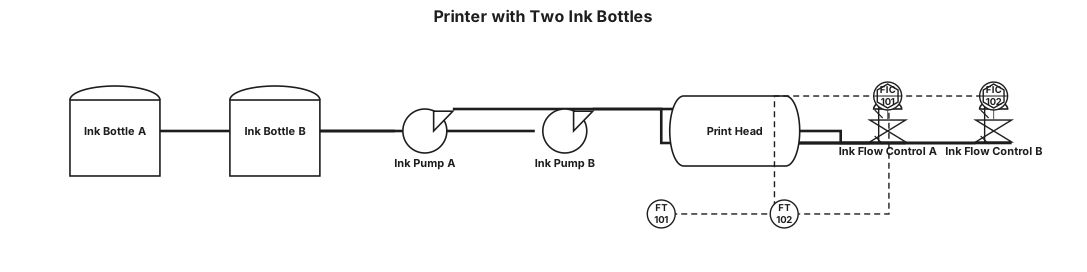
PRINTER WITH TWO INK BOTTLE
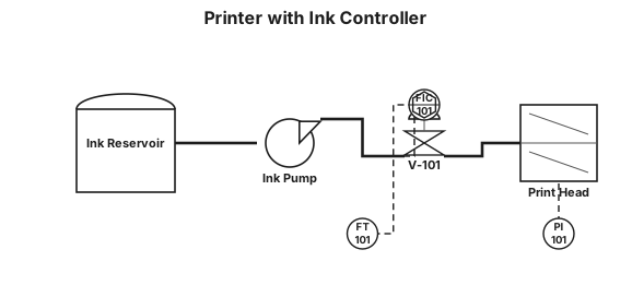
PRINTER WITH INK CONTROLLER
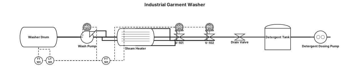
industrial washer used in garments
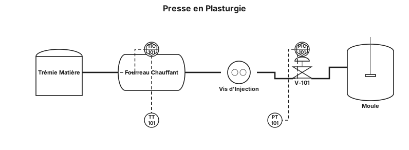
une presse en plastrugie
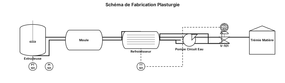
schéma de process ( schéma de fabrication) en industrie de la plasturgie
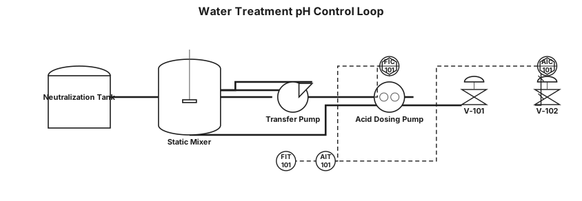
Water treatment loop with pH control and dosing pump

PID for steel rolling mill WTP