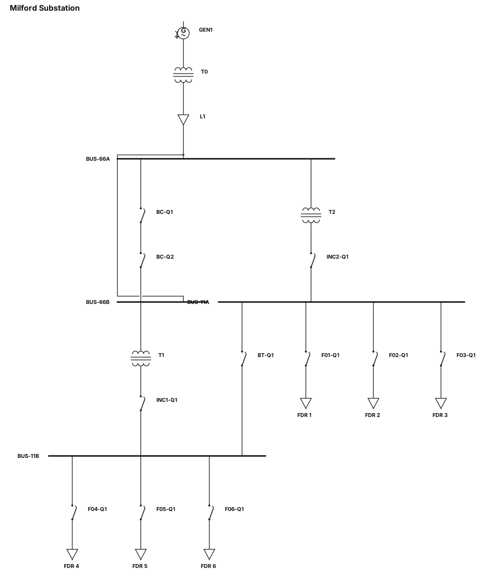
Industrial SCADA single-line diagram for "Milford Substation" on dark gray background. Top-to-bottom layout: - Top: Generator "GEN1" -> Transformer "T0" -> Line "L1" -> 66kV Busbars ("BUS-66A", "BUS-66B"). - Bus Coupler between 66kV busbars with two black square breaker blocks "BC-Q1", "BC-Q2". - Transformers "T2" (from BUS-66A) and "T1" (from BUS-66B) feed 11kV busbars ("BUS-11A", "BUS-11B") via black square incomer breakers "INC2-Q1" and "INC1-Q1". - Bus Tie between 11kV busbars with one black square breaker "BT-Q1". - Bottom Feeders: 6 outgoing lines with black square breakers "F01-Q1" to "F06-Q1" ending in load boxes "FDR 1" to "FDR 6". Style: Flat vector, 90-degree lines, clean white labels. ALL breakers/switches MUST be solid black squares with clean borders.
Diagram Examples from Real Visitor Prompts
Browse eligible diagrams shared by FreeDiagram visitors, inspect the exact prompts, and build your own version.
Browse 3261 real creationsSingle Line Diagrams
Showing 97–120 of 196. No stock examples or system defaults. Choose a tool, study a real result, then reopen its prompt as your starting point.
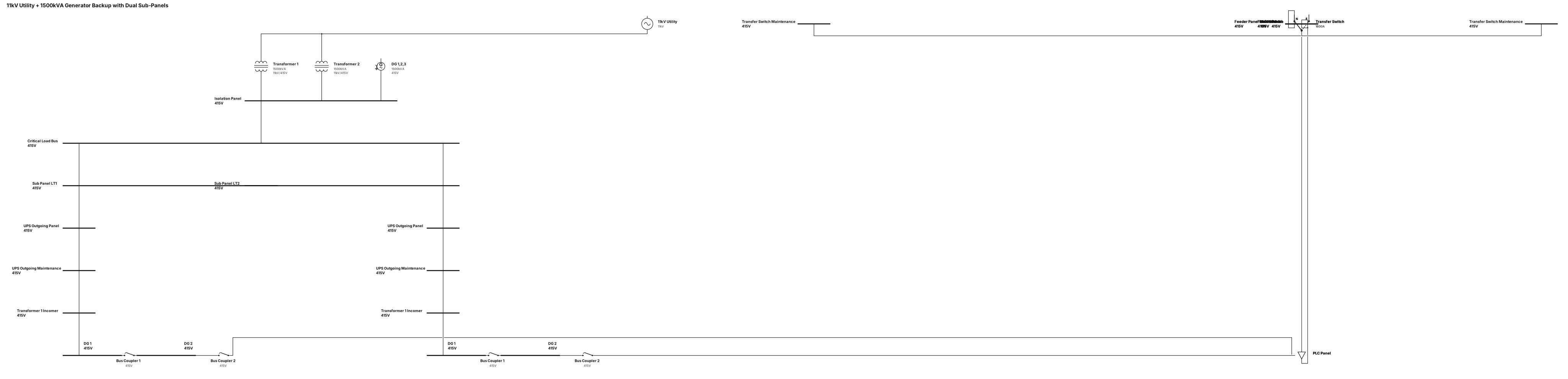
A 11kv input to isolation panel transformer 1 and 2 and 1500kva second source generators feeding same isolation panel Dg123 , then a critical-load bus with two sub panels LT1 and LT 2 .in LT 1 and LT 2 same pattern like first Ups out going panel , UPS out going maintenance, transformer 1 income,Dg 1 ,bus coupler,,DG 2,Bus coupler, PLC panel ,DG 3, feeder panel , feeder panel maintenance,mccb panel,transfer switch , transfer switch maintenance
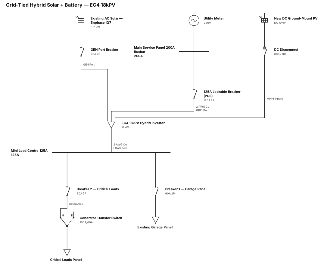
Here is the clean, copy-pasteable text for your AI diagram generator: System Overview: A grid-tied hybrid solar and battery system utilizing an EG4 18kPV inverter, integrating an existing 3.2kW AC-coupled solar array, a new DC-coupled ground-mount solar array, and a backup load center. Grid Connection: Utility Meter connected to a 200A Main Service Panel (200A Busbar). 125A, 2-pole lockable breaker installed at the bottom of the main panel. 2 AWG copper wire connecting the 125A breaker to the "GRID" port of the EG4 18kPV inverter. Inverter & Generation: Central Unit: EG4 18kPV Hybrid Inverter. Existing AC Solar: 3.2kW ground-mount array (Enphase IQ7 microinverters) connected to the "GEN" port via a 20A breaker. New DC Solar: Ground-mounted PV array connected to the MPPT inputs of the 18kPV via a DC disconnect switch. Backup Loads: 2 AWG copper wire connecting the "LOAD" port of the 18kPV to a 125A Mini Load Centre. The Mini Load Centre contains two 60A, 2-pole breakers. Breaker 1: Feeds the existing garage panel. Breaker 2: Feeds the existing critical loads panel via 6/3 Romex, passing through a 100A/60A generator transfer switch. Required Diagram Notes: Neutral and ground bonded at main service panel only. 125A backfeed breaker utilizes PCS for busbar compliance. Existing 3.2 kW AC-coupled system previously approved.
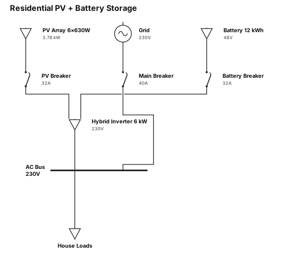
A single-line diagram for a: 1. 6 kW inverter ,single phase 2. 12kwh battery 3. 6 modules 630 W each
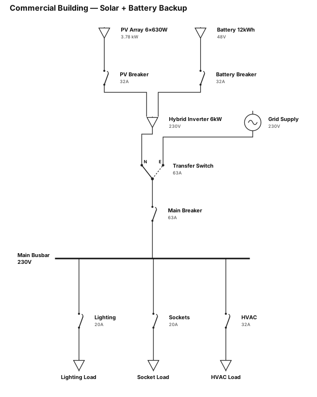
A single-line diagram for a commercial building: 6kW inverter, single phase. 12kwh battery. 6 modules 630W each
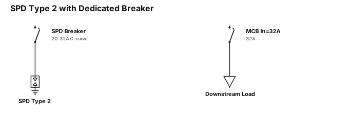
a single line diagram showing a spd type 2 connects via dedicated breaker (20–32 A C-curve). Downstream miniature circuit breaker ln=32A
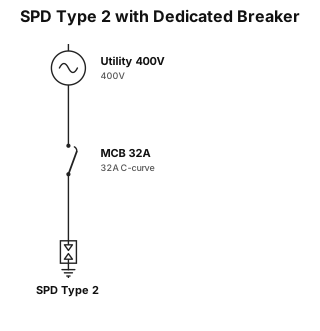
a single line diagram showing a spd type 2 connects via dedicated breaker (20–32 A C-curve), miniature circuit breaker ln=32A
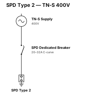
a single line diagram showing a spd type 2 connects via dedicated breaker (20–32 A C-curve), then a tn-s un=400V line
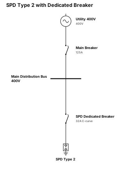
a single line diagram showing a spd type 2 connects via dedicated breaker (20–32 A C-curve)
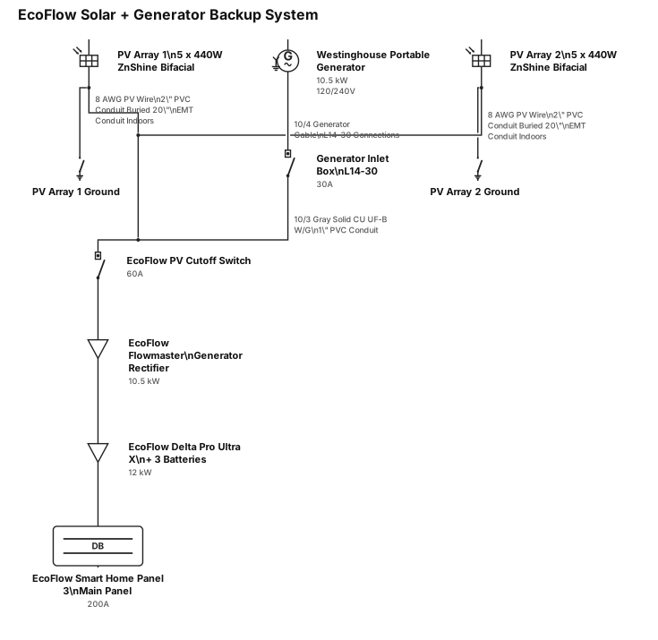
You are an expert electrician with 30 years of experience installing solar power. Create a single line electrical diagram used for permitting purposes for a system that has two solar panel installations that consists of 5 X 440 watt bifacial ZnShine solar panels each, grounded. The solar panels will be connected to the house using 8 gauge PV wiring within 2 inch PVC conduit buried 20 inches deep then enter the house and will continue in EMT conduit. There is also a Westinghouse portable generator capable of 10,500 watt, 30 amp power. The generator will enter the house through a generator inlet box connected by a 10/4 generator cable with L14-30 connections. The generator power will continue with 10/3 Gray Solid CU UF-B W/G Wire and be run through 1 inch PVC conduit then be connected to an EcoFlow PV cutoff switch. The solar panels also feed into the same Ecoflow PV cutoff switch. The generator and PV power then connect to an EcoFlow Flowmaster generator rectifier and then to an Ecoflow Delta Pro Ultra X with three batteries. This is then connected to an EcoFlow Smart Home Panel 3, which is the home's main panel. All EcoFlow components connect with the EcoFlow proprietary connections. Create the single line diagram to industry standards. By "industry standards" I mean the standard for single line diagrams, not electrical code standards. The output will be an image or diagram that I can download as a PDF file. Do not place text over the lines in the drawing.
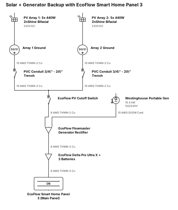
You are an expert electrician with 30 years of experience installing Create a single line electrical diagram used for permitting purposes for a system that has two solar panel installations that consists of 5 X 440 watt bifacial ZnShine solar panels each, grounded. There is also a Westinghouse portable generator capable of 10,500 watt, 30 amp power. The solar panels feed into an Ecoflow PV cutoff switch. The generator and PV power then connect to an EcoFlow Flowmaster generator rectifier and then to an Ecoflow Delta Pro Ultra X with three batteries. This is then connected to an EcoFlow Smart Home Panel 3, which is the home's main panel. Create the single line diagram to industry standards. By "industry standards" I mean the standard for single line diagrams, not electrical code standards. The output will be an image or diagram that I can download as a PDF file. Add in the gauge of the wire and what conduit will be used. Include that the PVC pipe from the solar arrays is to be buried in a trench 2o inches underground. Do not place text over the lines in the drawing.
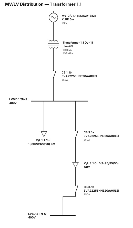
MV-C/L 1.1 N2XS2Y 5 m XLPE 3 x 25 MV-C/L 1.1 N2XS2Y 5 m XLPE 3 x 25 Transformer 1.1 Sn =160 kVA / AN ukr= 4% 10/0.4 kV Dyn11 4GB52443F C/L 1.1 Cable/Line 5 m Cu 1(3x120/120/70) CB 1.1b Circuit-breaker In=250 A 3VA22255HN320AA0/LSI LVMD 1 TN-S Un=400 V CB 3.1a Circuit-breaker In=250 A 3VA22255HN320AA0/LSI C/L 3.1 Cable/Line 60 m Cu 1(3x95/95/50) CB 3.1b Circuit-breaker In=250 A 3VA22255HN320AA0/LSI LVSD 3 TN-C Un=400 V
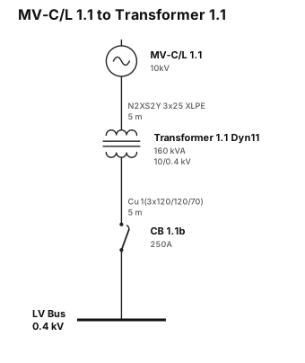
MV-C/L 1.1 N2XS2Y 5 m XLPE 3 x 25 MV-C/L 1.1 N2XS2Y 5 m XLPE 3 x 25 Transformer 1.1 Sn =160 kVA / AN ukr= 4% 10/0.4 kV Dyn11 4GB52443F C/L 1.1 Cable/Line 5 m Cu 1(3x120/120/70) CB 1.1b Circuit-breaker In=250 A 3VA22255HN320AA0/LSI
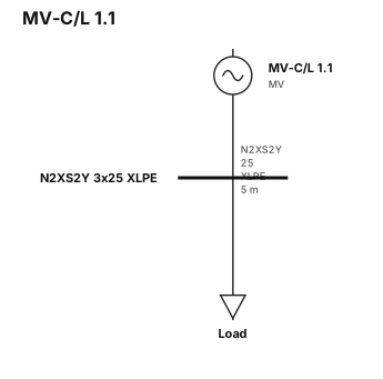
MV-C/L 1.1 N2XS2Y 5 m XLPE 3 x 25
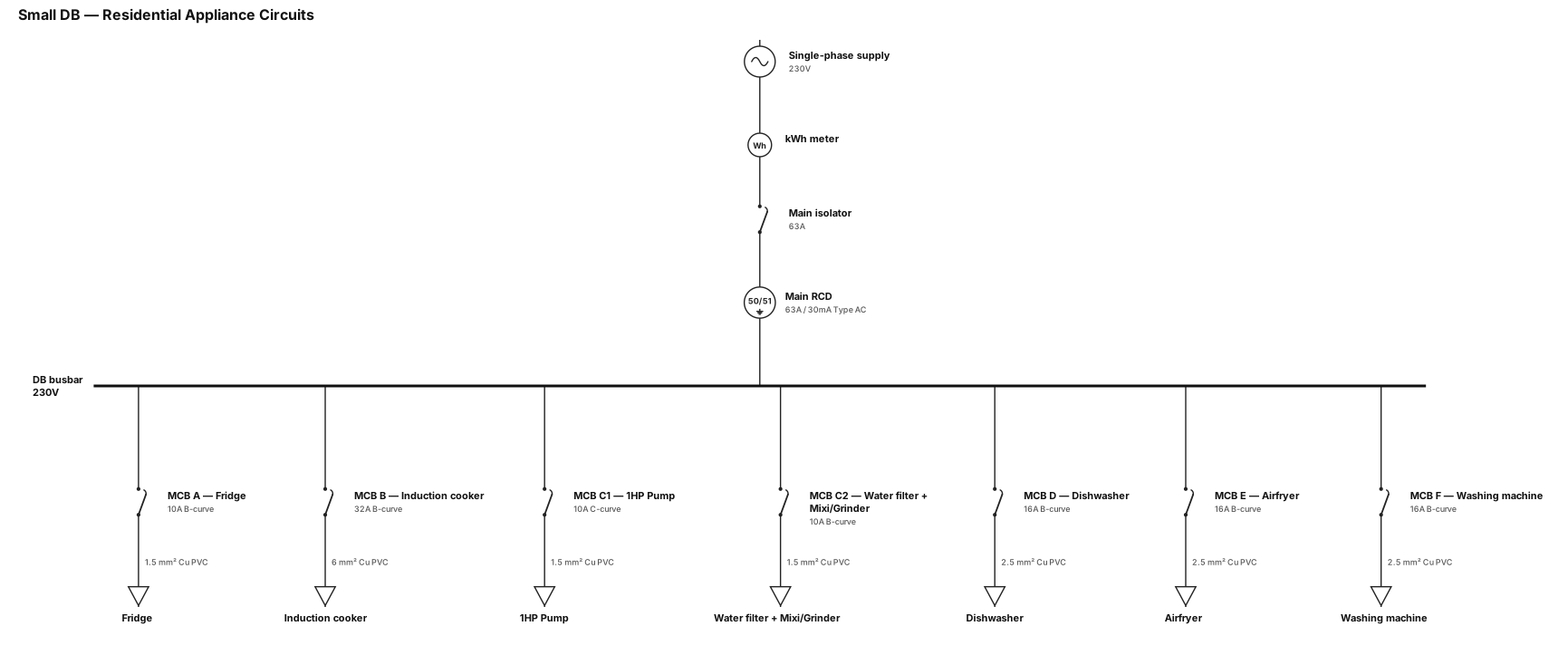
A single-line diagram for a small DB which power,if a single phase db has to acomodate circuits A- fridge, B-Induction cooker, C-1Hp Pump, Water Filter, Mixi, grinder, D-Dishwasher, E-Airfryer,F-Washing machine. water filter will be always on, mixi and grinder maynot be used at the same time. what should be the MCB sizings and wire guage of each phase, neutral and earth at a minimum. should we split Circuit C
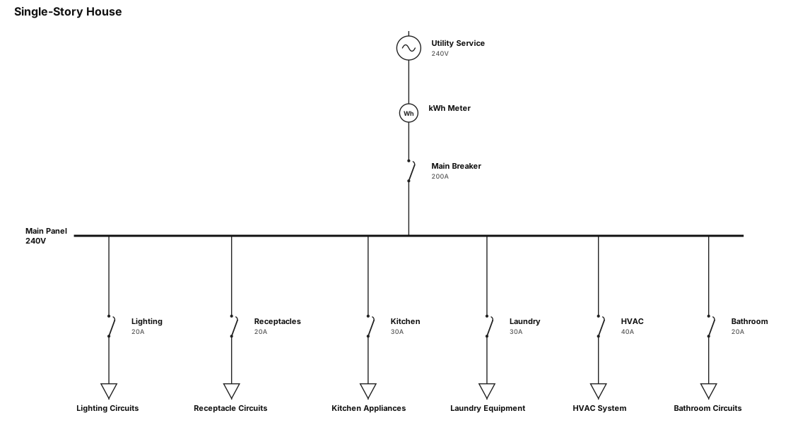
A single-line diagram for a single storye house
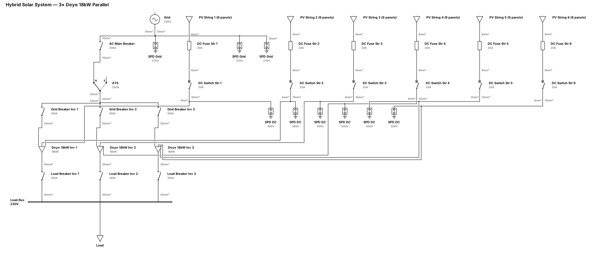
single line diagram of hybrid solar system with 3pcs Deye 18kw single phase inverter in parallel, 3pcs 100a ac breaker load side and 3pcs 100a ac breaker grid side using 30mm wire and 3pcs 275v spd using 10mm wire grid side 1 pc 200a ac main breaker using 70mm wire and 250a ATS, 6 strings with 9 panels using 20a dc fuse and 20a dc breaker switch with 6mm wire with 6pcs 500v spd using 10mm ground wire

A single-line diagram for a AC charging facility: utility feed through a main transformer (2000 KVA) via main breaker of 2500A to a 480V switchboard, from the sitchboard to 2 AC cabinets with a 400A main breaker each, from the cabinets to 40 AC outlets of 22 kW
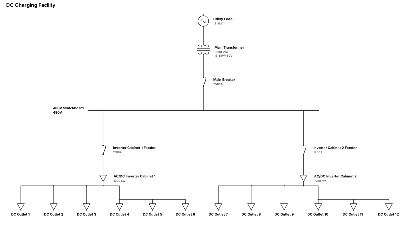
A single-line diagram for a DC charging facility: utility feed through a main transformer (2000 KVA) via main breaker of 2500A to a 480V switchboard, from the sitchboard to 2 AC/DC inverter cabinets, from the cabinets to 12 DC outlets
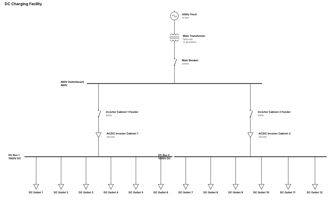
A single-line diagram for a DC charging facility: utility feed through a main transformer (1600 KVA) vai main breaker to a 480V switchboard, from the sitchboard to 2 AC/DC inverter cabinets, from the cabinets to 12 DC outlets
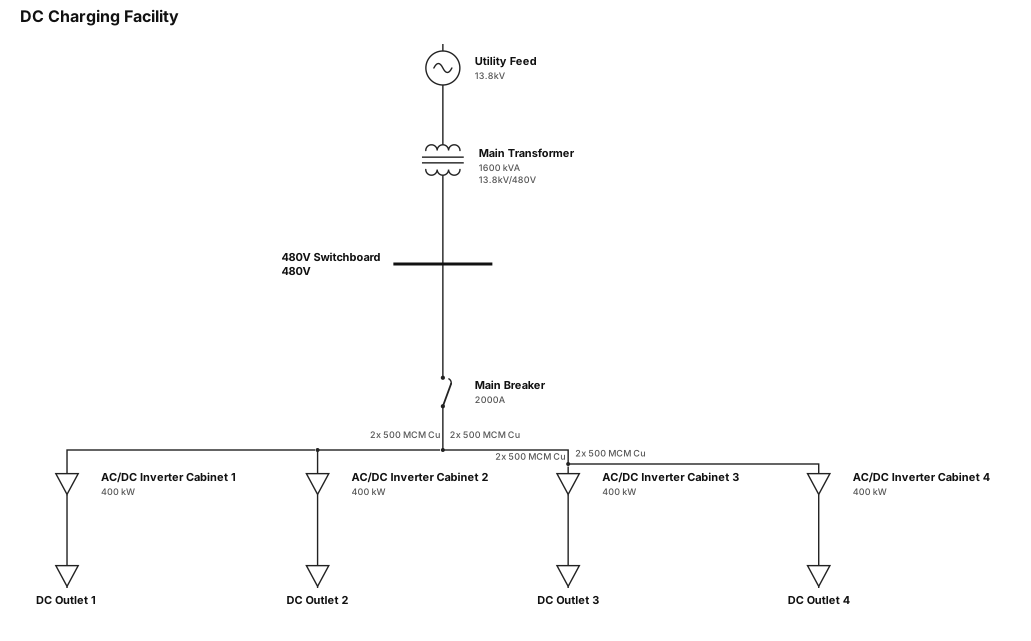
A single-line diagram for a DC charging facility: utility feed through a main transformer (1600 KVA) to a 480V switchboard, then with two parallel cable to 4 AC/DC inverter cabinets, from invertecabinets to DC outlets
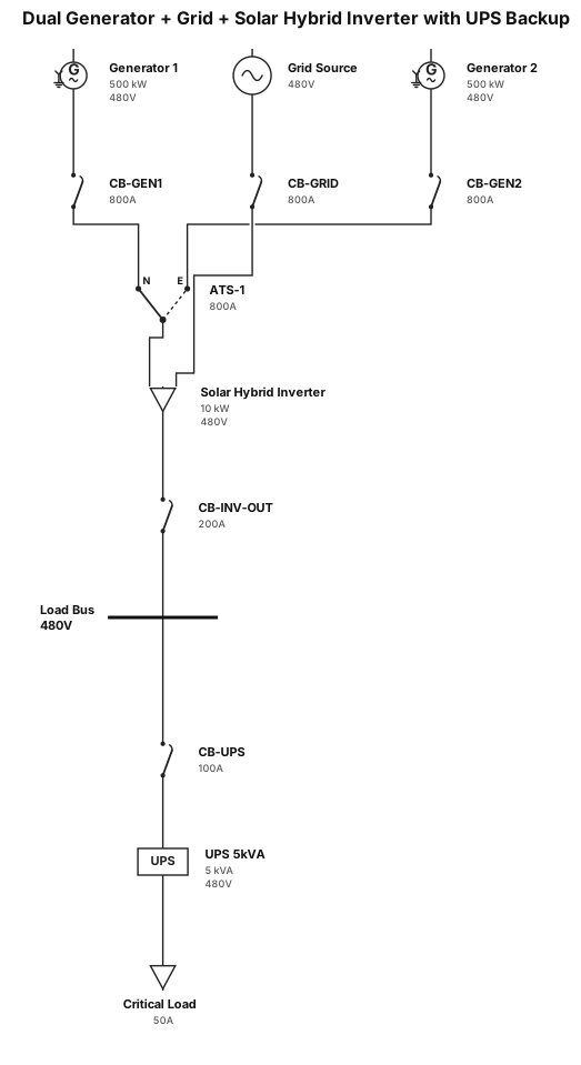
ack as professional electrician and create a SLD for. two (2) generators connected to the input of ATS then the output of ATS is connected to the solar hybrid inviter along with grid source. then the output of inverter is connected to line side of circuit breaker then a 5kva UPS is connected to the load site of the circuit breaker. put a standard circuit breaker where need a breaker.
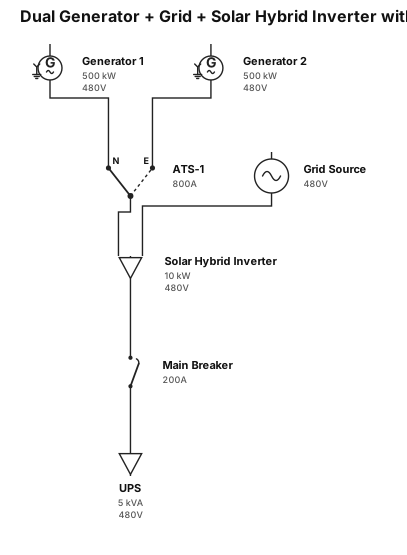
ack as professional electrician and create a SLD for. two (2) generators connected to the input of ATS then the output of ATS is connected to the solar hybrid inviter along with grid source. then the output of inverter is connected to line side of circuit breaker then a 5kva UPS is connected to the load site of the circuit breaker.
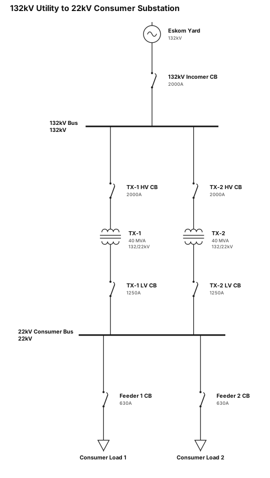
132KV from utility, eskom yard with 132KV:22kv stepdown transformers, CONSUMER SUBSTATION