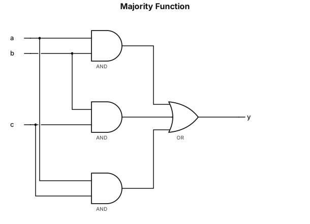
a.b+b.c+a.c
NODE ARCHIVE · REAL DIAGRAM BRIEFS
Diagram Examples from Real Visitor Prompts
Browse eligible diagrams shared by FreeDiagram visitors, inspect the exact prompts, and build your own version.
Browse 3261 real creationsCOMMUNITY OUTPUTS · EXACT PROMPTS
Logic Gate
Showing 121–144 of 288. No stock examples or system defaults. Choose a tool, study a real result, then reopen its prompt as your starting point.
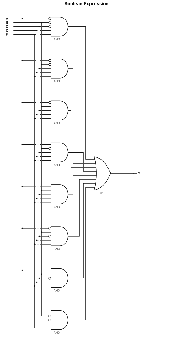
A′B′C′DF+A′B′CDF+A′BCDF+AB′CDF+ABCDF+A′BC′DF+ABC′DF+AB′C′DF
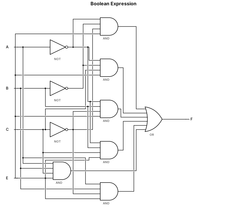
A′B′C′E+A′B′CE+A′BC′E+A′BCE+ABC′E+ABCE
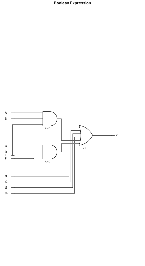
Y=A′BC+AB′D+AC′E+BCD′+ABE+CDF
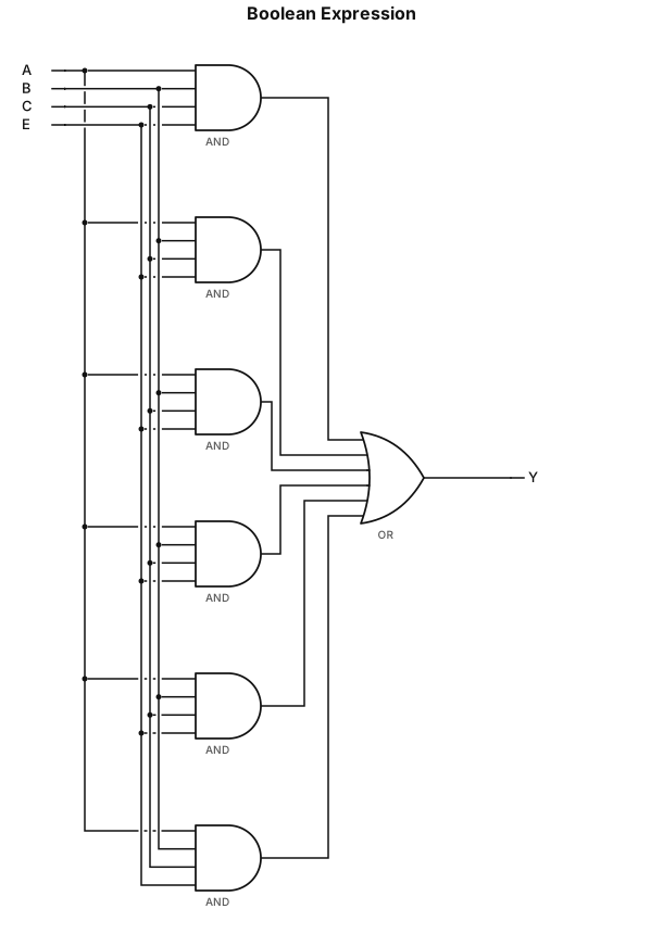
A′B′C′E+A′B′CE+A′BCE+ABCE+ABC′E+A′BC′E
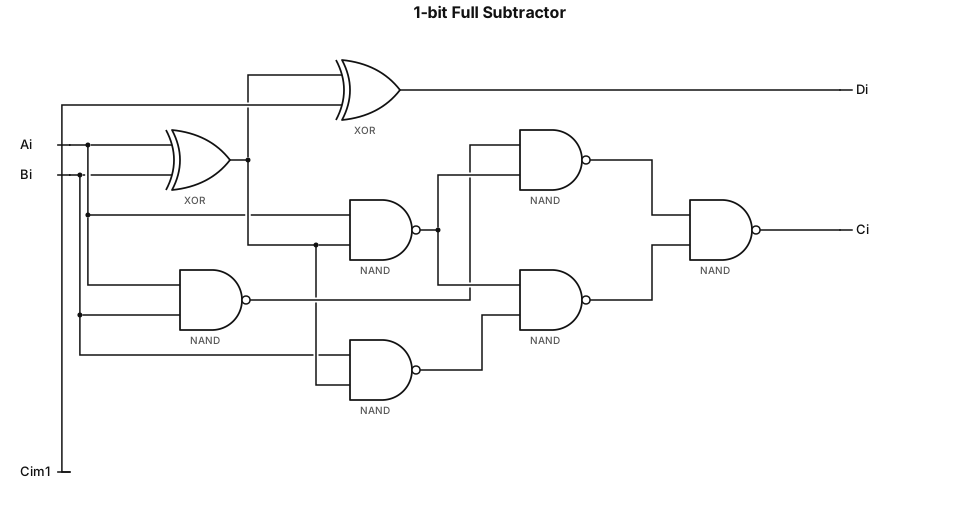
Draw digital logic circuit for 1-bit full subtractor. Inputs: Ai, Bi, C_{i-1}. Output: Di, Ci. Di = Ai xor Bi xor C_{i-1}, use two 2-input XOR gates(74LS86). Ci = NAND combination, use multiple 2-input NAND gates(74LS00). Standard IEEE logic symbols, clean diagram for lab report.
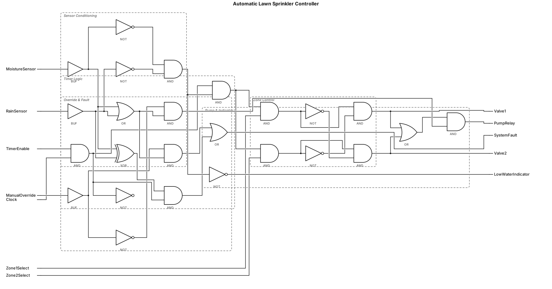
make a logic circuit consisting of 20 logic gates on automatic lawn sprinkler controller.
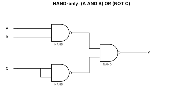
NAND-only implementation of the expression (A AND B) OR (NOT C)
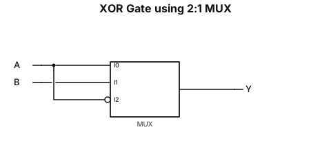
xor gate using 2:1 mux
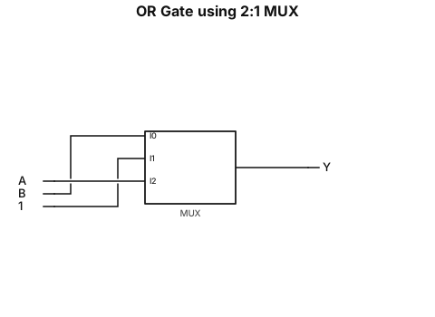
or gate using 2:1 mux
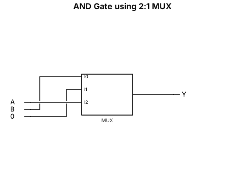
and gate using 2:1 mux with point the select line
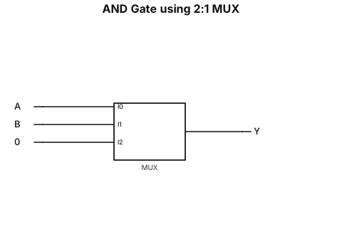
and gate using 2:1 mux with point the slect line
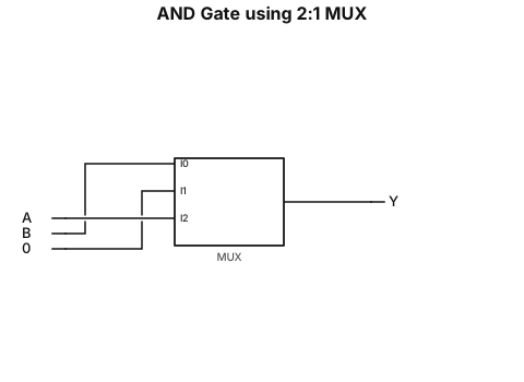
and gate using 2:1 mux
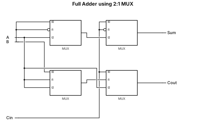
full adder using 2:1 mux with select line mention in down side
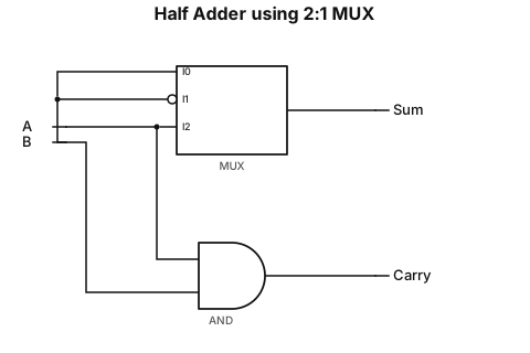
half adder using 2:1 mux with select line mention in down side
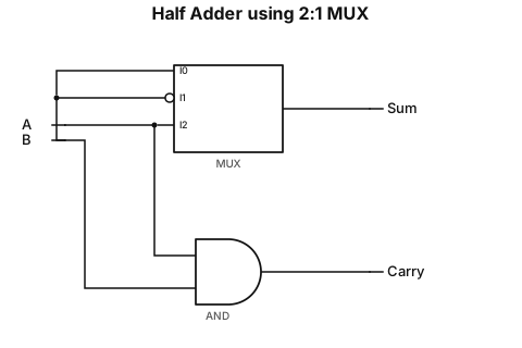
half adder using 2:1 mux with select line
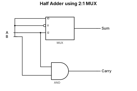
half adder using 2:1 mux
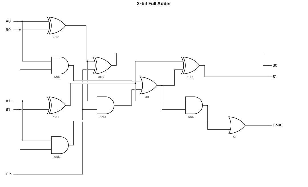
A logic gate circuit for a 2-bit full adder using AND, OR, and XOR gates with inputs A, B, and carry-in, and outputs sum and carry-out
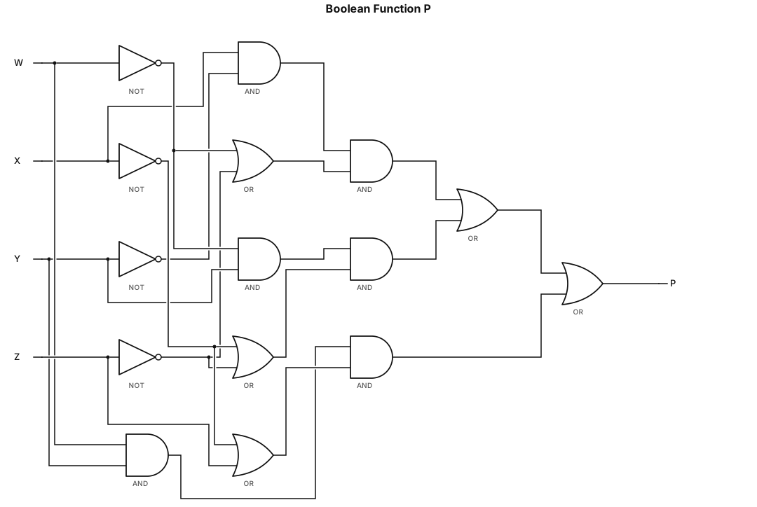
Draw the logic circuit diagram (strictly using, NOT and/or two-input AND/OR gates) for P = XY’(W’+Z’)+W’Y(X’+Z’)+WY(X’+Z)
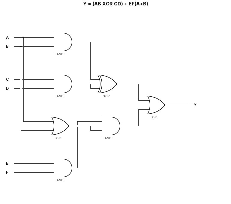
a logic circuit diagram (strictly using, NOT and/or two-input AND/OR gates) Y = (AB XOR CD) + EF(A+B)
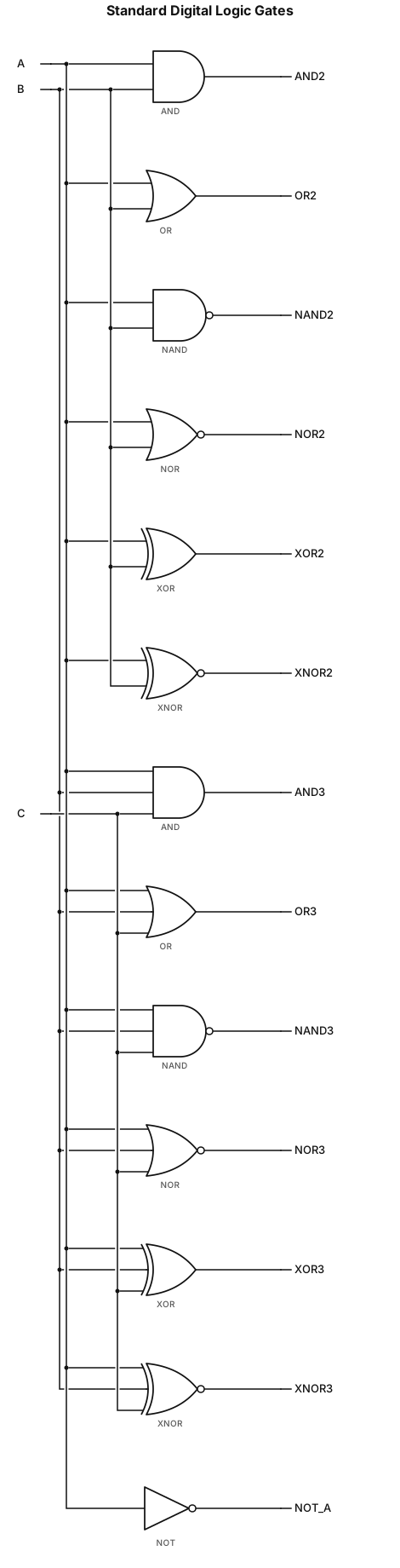
Generate a complete set of standard digital logic gate diagrams for my DLD assignment. Include AND, OR, NAND, NOR, XOR, and XNOR gates with both 2-input (A, B) and 3-input (A, B, C) versions. Include the NOT gate with one input and its output. Use standard ANSI logic gate symbols, black-and-white line drawings, clearly labeled input and output pins, plain white background, and a neat academic style. Create separate, accurate diagrams for each gate, suitable for insertion into a Microsoft Word document.
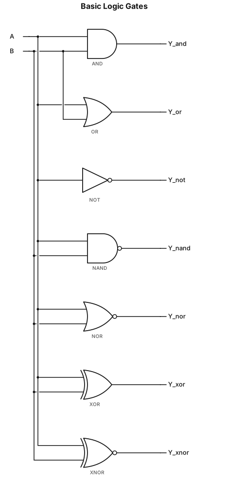
A logic gates diagram in which each logic gates is seperate use with 2 pins
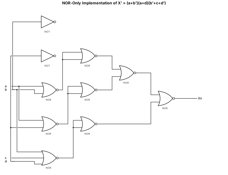
make me a Nor only gate diagram for X'=(a+b')(a+d)(b'+c+d')
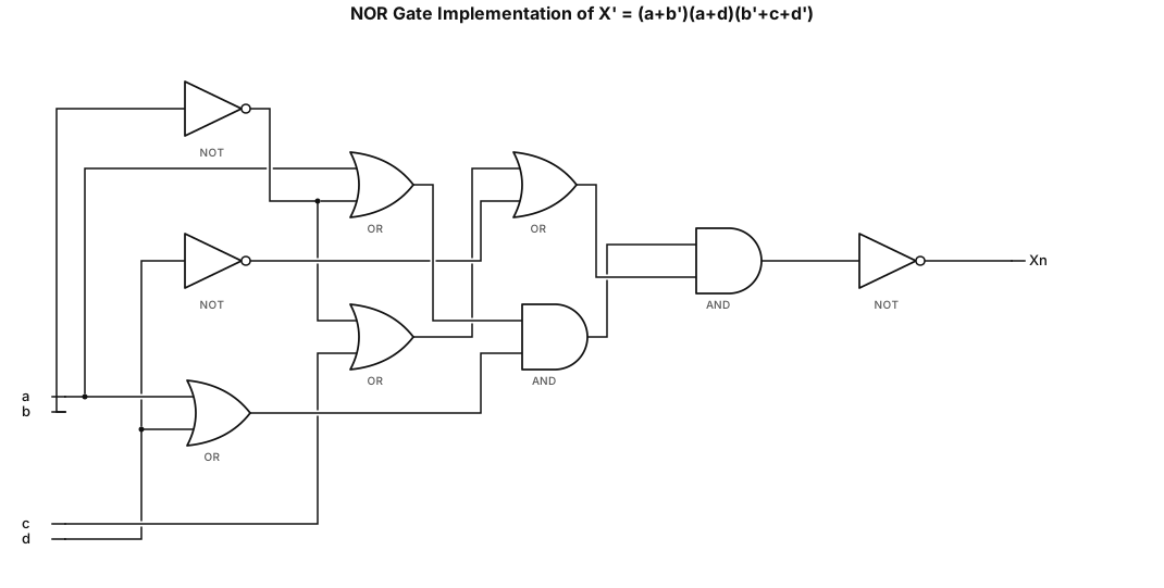
make me a Nor gate diagram for X'=(a+b')(a+d)(b'+c+d')