
Storage tank to valve #1 to valve #4 to transfer pump to valve #5 to valve#8 to valve #9 to machine to valve 13 List valve #'s 2, 3, 6, 7, 10, 11 and 12 as closed
NODE ARCHIVE · REAL DIAGRAM BRIEFS
Diagram Examples from Real Visitor Prompts
Browse eligible diagrams shared by FreeDiagram visitors, inspect the exact prompts, and build your own version.
Browse 3261 real creationsCOMMUNITY OUTPUTS · EXACT PROMPTS
Pid
Showing 121–142 of 142. No stock examples or system defaults. Choose a tool, study a real result, then reopen its prompt as your starting point.

Storage tank to valve #1 to valve #4 to transfer pump to valve #5 to valve#8 to valve #9 to machine to valve 13
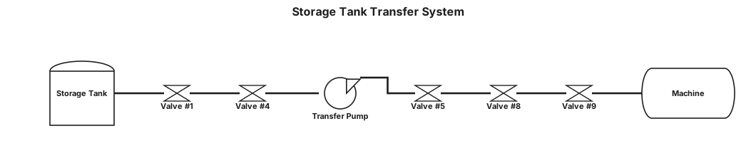
Storage tank to valve #1 to valve #4 to transfer pump to valve #5 to valve#8 to valve #9 to machine
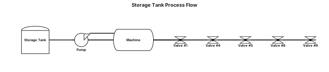
Storage tank ball valve #1 valve #4 pump valve #5 valve#8 valve #9 machine
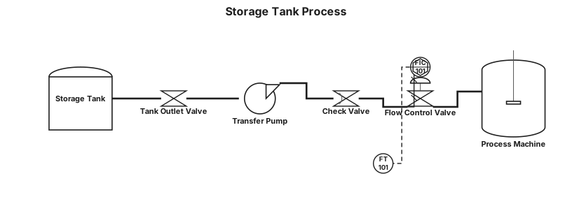
Storage tank valve valve pump valve valve machine
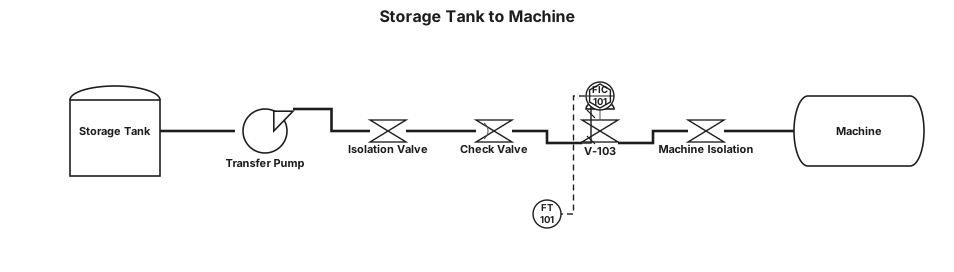
Storage tank to machine through 4 valves and a pump

Water/Sugar & Ingredients→ CMC MIXER →Juice Blending Tanks → UHT → Juice Storage/Buffer Tank → Cup & Bottle Fillers → CIP/Drain, A Piping and Instrumentation Diagram Showing both fillers, cup and bottle fillers, CIP system, Simple syrup system, Divert Panels, Utility connections to UHT and Filler, water storage tank and its UV filtration setup

Water/Sugar & Ingredients→ CMC MIXER →Juice Blending Tanks → UHT → Juice Storage/Buffer Tank → Cup & Bottle Fillers → CIP/Drain
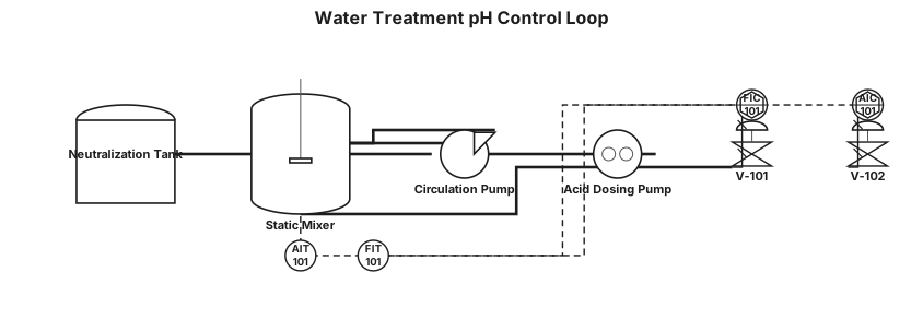
Water treatment loop with pH control and dosing pump
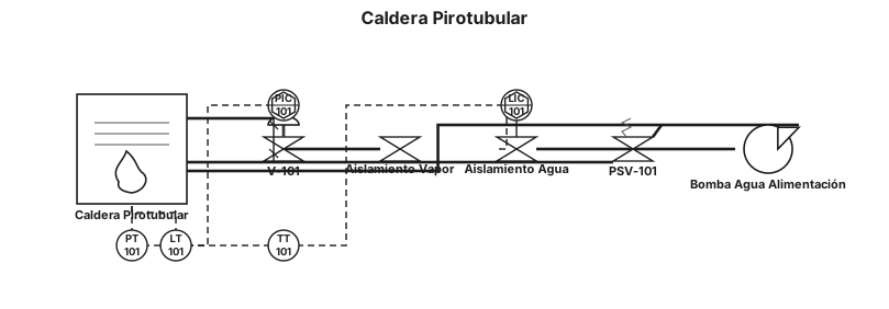
caldera pirotubular
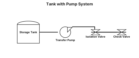
tank with pump system
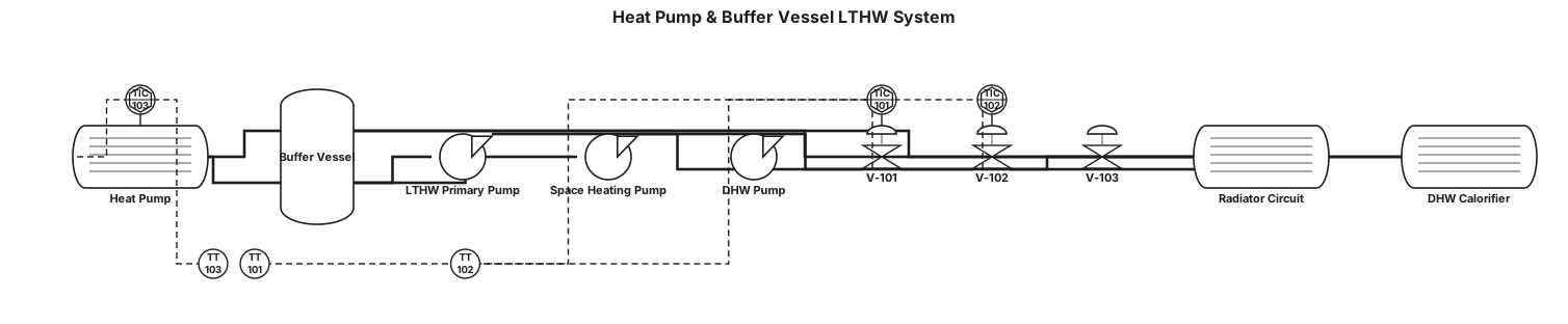
A P&ID for a heat pump and buffer vessell, feeding a low temperature hot water system with a space heating circuit with radiators and hot water circcuits. show flow temps as 70 degree c and return as 40 degree
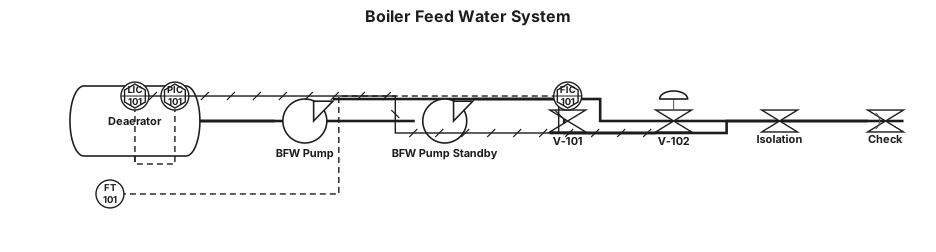
Boiler feed water system with deaerator and feed pump control
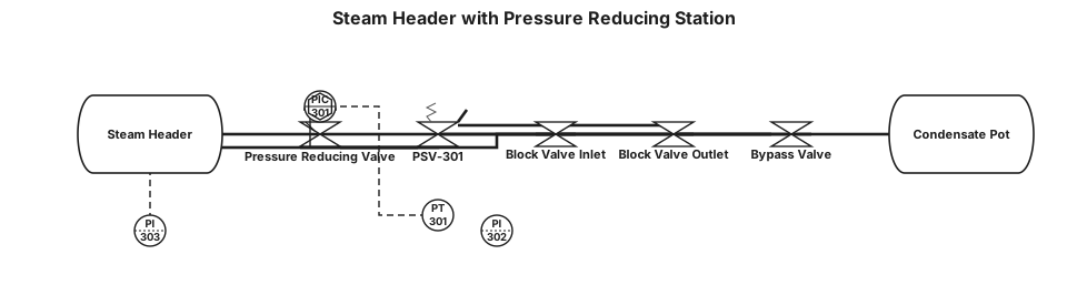
Steam header with pressure reducing station and safety relief
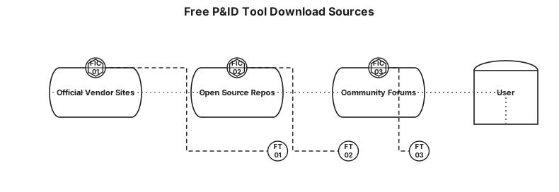
where can I download P&ID tool free

where can I get P&ID tool free
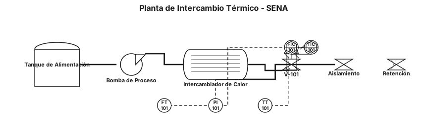
necesito un P&ID DE LA PLANTA DE INTERCAMBIOS TERMICOS , DE TODA LA PLANTA PUEDES SACAR LA PLANTA DE LA PAGINA DEL SENA QUE ESTE ACTUALIZADO CON LA NORMA ANSI/ISA-5.1-2009

Low-pressure exhaust steam from the turbine enters the direct-contact condenser HE-201, where it is condensed by intimate contact with circulating cooling water; the non-condensable gases (NCGs) collect at the top of HE-201 and are routed via stream 5 to reinjection, while the condensed steam mixed with cooling water ("brine") collects at the bottom of HE-201 and is pumped by P-202 via stream 6 to preheating. The cooling water side is served by cooling tower CT-201, which receives warm cooling water return from the condensing loop plus fresh makeup water (cooling water supply); cooled water collects in the CT-201 basin and is pumped by P-201 via stream 8 back up to HE-201 to sustain the direct-contact condensing duty, closing the loop with return stream 7 feeding into CT-201. Blowdown is taken from the cooling water circuit near CT-201/P-201 via stream 9 to reinjection to control dissolved solids buildup, and a second cooling water supply take-off exits the circuit to an off-page user. Key equipment: HE-201 (direct-contact condenser, vertical vessel), CT-201 (cooling tower), P-201 (cooling water circulation pump, CT-201→HE-201), P-202 (brine/condensate pump, HE-201→preheating); for the P&ID, add line numbers and pipe specs on all segments, isolation valves at every equipment nozzle, check valves on both pump discharges, level control (LT/LC) on the HE-201 hotwell driving P-202 and the brine control valve, conductivity-based blowdown control (AT/valve) on stream 9, basin level/makeup control on CT-201, pressure/temperature instrumentation (PT/TT) on the exhaust steam line and HE-201, and sheet-number references on all off-page connectors (turbine, NCG reinjection, preheating, cooling water supply/source, blowdown reinjection).
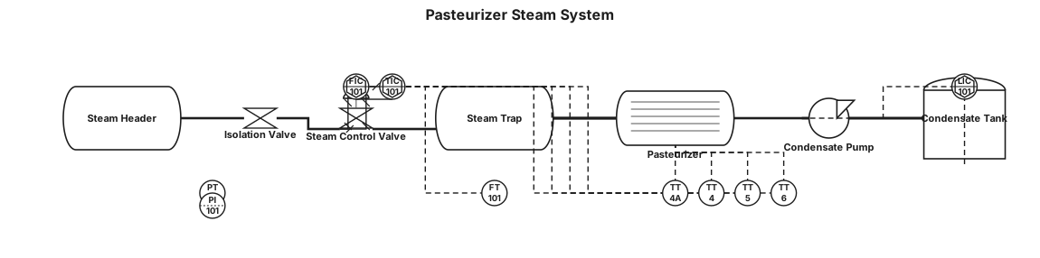
Pasteurizer steam system: Steam header → isolation valve → steam control valve → steam trap → condensate return line. Pasteurizer has temperature transmitters TT4A, TT4, TT5 and TT6. Condensate is collected and returned by a condensate pump. Show pressure, temperature and flow instrumentation.
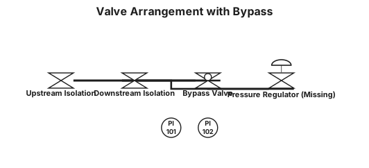
A P&iD of valve arrangement having missing pressure regulator but have isolating upstream and downstream valves with bypass globe valve

The system is equipped with 2 sets of vertical U‑tube semi‑volume water‑to‑water heat exchangers. The heat exchanger shell diameter is DN1200, volume 1.4 m³, design pressure of tube‑side and shell‑side is 1.0 MPa, heat transfer area is 16.5 ㎡. Shell, tube‑side and heat exchange tubes are made of 304 stainless steel; supports are 304 stainless steel plus carbon steel. Auxiliary equipment includes circulating water pumps and pressure tanks. Instruments and accessories: pressure gauges, thermometers, transmitters, safety valves, blow‑down valves. The system includes primary‑side pipelines & valves, secondary‑side pipelines & valves. Control objectives: Complete heat exchange between primary and secondary side to meet cooling and heating requirements of the system. Monitor pressure and temperature of heat exchanger medium. Safety overpressure relief via safety valves. Blow‑down function through blow‑down valves. Circulating pumps provide medium circulation. All equipment, instruments and valves shall be configured in accordance with construction drawings and relevant design codes and specifications
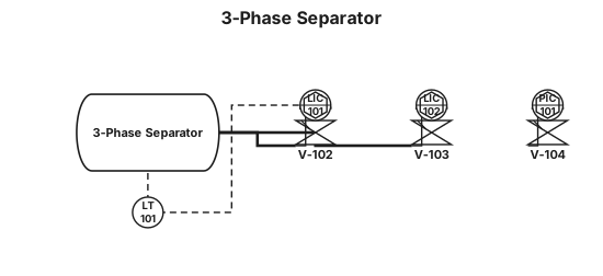
3-phase separator