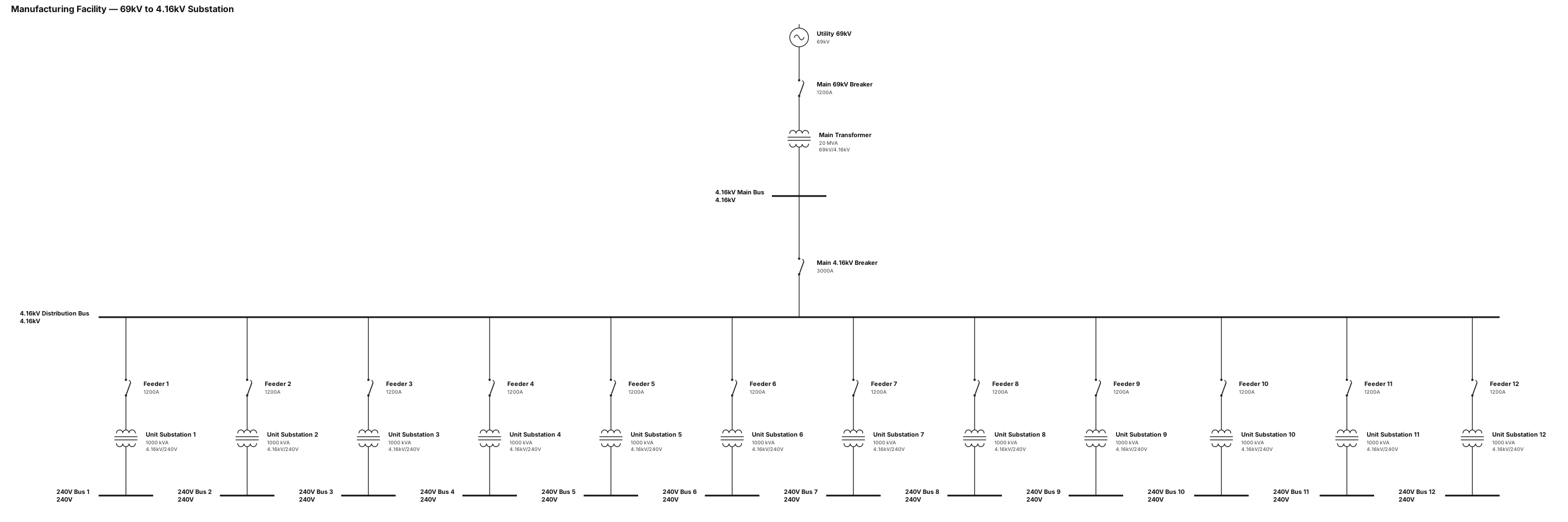
A single-line diagram for a manufacturing facility. 69KV to 4.16KV substation. (12) 4160V to 240V unit substations.
NODE ARCHIVE · REAL DIAGRAM BRIEFS
Diagram Examples from Real Visitor Prompts
Browse eligible diagrams shared by FreeDiagram visitors, inspect the exact prompts, and build your own version.
Browse 3261 real creationsCOMMUNITY OUTPUTS · EXACT PROMPTS
Single Line Diagrams
Showing 121–144 of 196. No stock examples or system defaults. Choose a tool, study a real result, then reopen its prompt as your starting point.
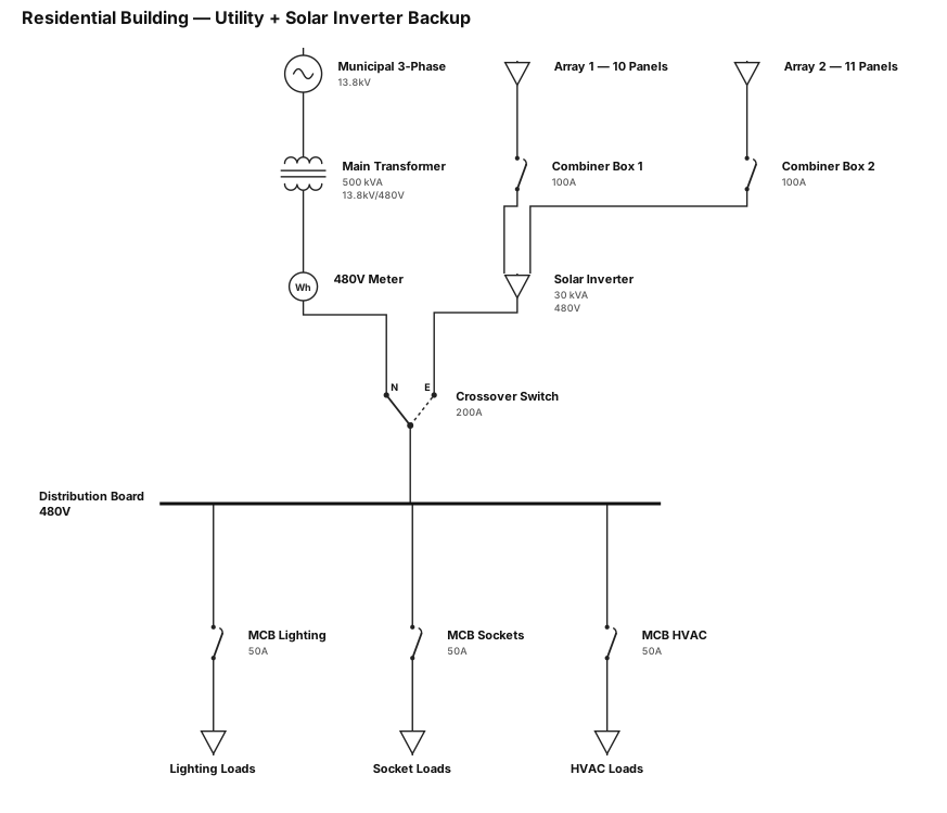
A single-line diagram for a residential building: utility feed through a main transformer to a 480V meter, then to a crossover switch, the crossover switch is fed by municipal 3 phase and alternative inverter 30kva with solar that has 21 pannels in 2 arrays with combiner boxes for each array. the power goes from the crossover switch to a db board
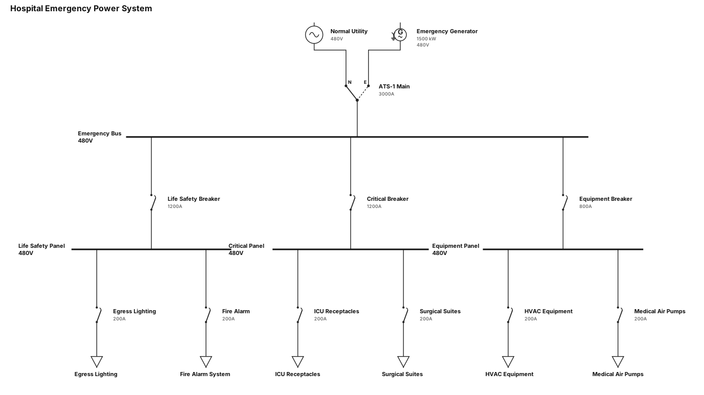
Hospital emergency power with ATS and critical branch panels
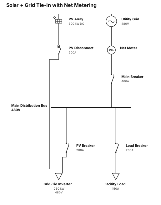
Solar plus grid tie-in with inverter and net metering disconnect
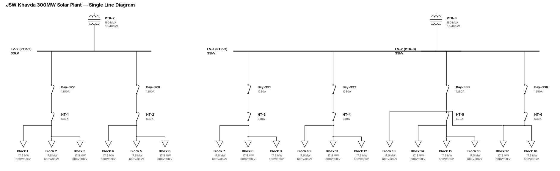
Create a professional, JSW Khavda 300MW Single Line Diagram (SLD) in IEC standard format. System Details: • PTR-2 - LV-2 - Bay-327 → HT-1 → Blocks 1, 2, 3 - Bay-328 → HT-2 → Blocks 4, 5, 6 • PTR-3 - LV-1 - Bay-331 → HT-3 → Blocks 7, 8, 9 - Bay-332 → HT-4 → Blocks 10, 11, 12 - Bay-333 → HT-5 → Blocks 14, 15, 16 - PTR-3 - LV-2 - Bay-336 → HT-6 → Blocks 13, 17, 18 Requirements: • Professional engineering drawing style. • Clean symmetrical layout with proper alignment. • IEC electrical symbols. • Distinguish PTR, LV Bus, Bays, HT Feeders, and Block connections using color coding. • Show power flow direction with arrows. • Include breaker symbols where appropriate. • Display equipment ratings placeholders (Voltage, Current, Transformer Rating). • White background, CAD-quality appearance. • Suitable for substation design review and technical documentation. • Use clear labels, professional fonts, and organized hierarchy. Layout: Top Level → PTR-2 and PTR-3 Second Level → LV Bus Sections Third Level → Bays Fourth Level → HT Feeders Bottom Level → Connected Solar Blocks rating of equipment's PTR : 33/400KV BLOCK : 600v/33kv (17.5MW ac capacity) HT : 33kv Create the diagram similar to an AutoCAD electrical SLD used in utility-scale solar plants.
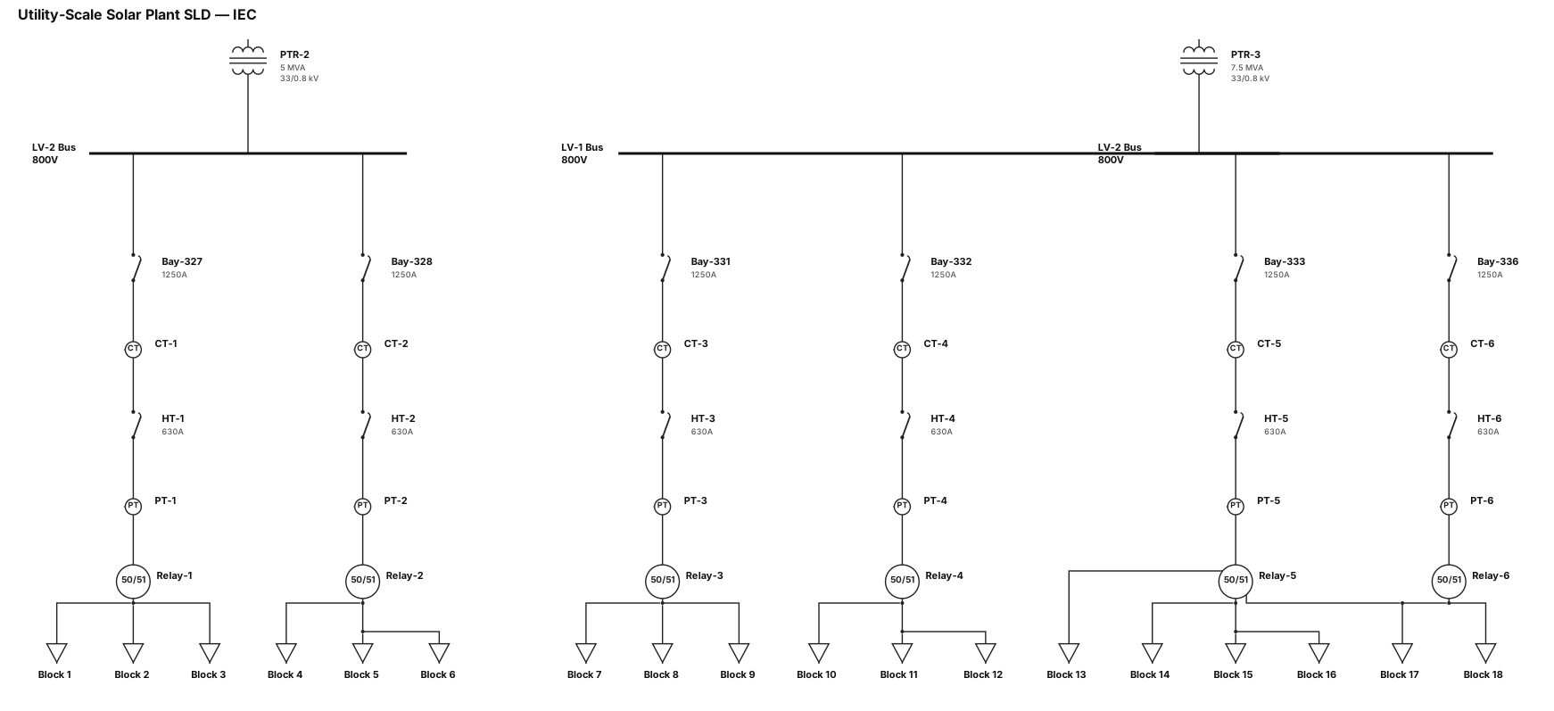
Create a professional, utility-scale solar power plant Single Line Diagram (SLD) in IEC standard format. System Details: • PTR-2 (LV-2) - Bay-327 → HT-1 → Blocks 1, 2, 3 - Bay-328 → HT-2 → Blocks 4, 5, 6 • PTR-3 - LV-1 - Bay-331 → HT-3 → Blocks 7, 8, 9 - Bay-332 → HT-4 → Blocks 10, 11, 12 - Bay-333 → HT-5 → Blocks 14, 15, 16 - LV-2 - Bay-336 → HT-6 → Blocks 13, 17, 18 Requirements: • Professional engineering drawing style. • Clean symmetrical layout with proper alignment. • IEC electrical symbols. • Distinguish PTR, LV Bus, Bays, HT Feeders, and Block connections using color coding. • Show power flow direction with arrows. • Include breaker, isolator, CT/PT, protection relay symbols where appropriate. • Display equipment ratings placeholders (Voltage, Current, Transformer Rating). • White background, CAD-quality appearance. • Suitable for substation design review and technical documentation. • Use clear labels, professional fonts, and organized hierarchy. • Output in high-resolution vector-style schematic format. Layout: Top Level → PTR-2 and PTR-3 Second Level → LV Bus Sections Third Level → Bays Fourth Level → HT Feeders Bottom Level → Connected Solar Blocks Create the diagram similar to an AutoCAD electrical SLD used in utility-scale solar plants.
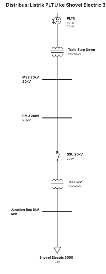
buatkan saya sebuah single line diagram alur distribusi listrik, mulai dari PLTU - Trafo step down - MSS (main switch station) 20kv - RMU (ring main unit) 20kv - SSU (stop switch unit) 20 kv - TSU (transformer switch unit) 6kv - junction box 6kv - Shovel electric 3000 6kv
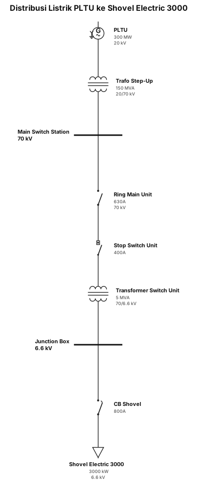
buatkan saya sebuah single line diagram alur distribusi listrik, mulai dari PLTU - Trafo - MSS (main switch station) - RMU (ring main unit) - SSU (stop switch unit) - TSU (transformer switch unit - junction box - Shovel electric 3000
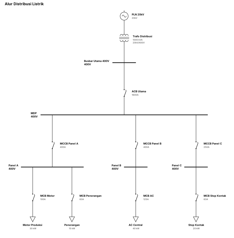
buatkan saya sebuah single line diagram alur distribusi listrik.
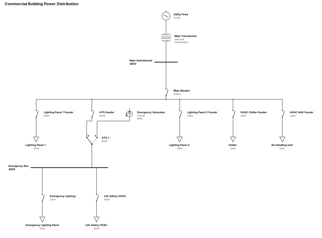
A single-line diagram for a commercial building: utility feed through a main transformer to a 480V switchboard, then to lighting panels, HVAC equipment, and an emergency generator with ATS
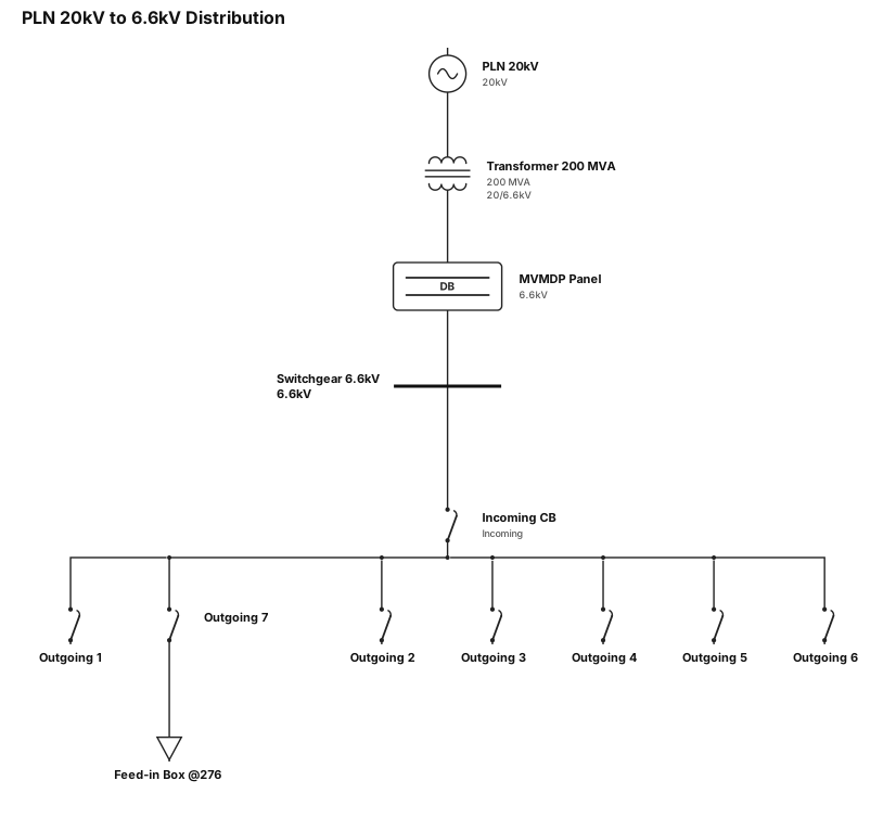
PLN 20KV TO 6,6KV. MVMDP panel (detail) TO SWITCHGEAR 6,6KV to panel feed point . tranformer 200mv. switchgear 1 incoming-7 outgoing to feedin box (@276)
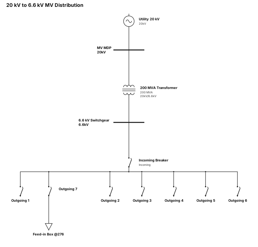
20 KV TO 6,6KV. MVMDP TO SWITCHGEAR 6,6KV. tranformer 200mv. switchgear 1 incoming-7 outgoing to feedin box (@276)
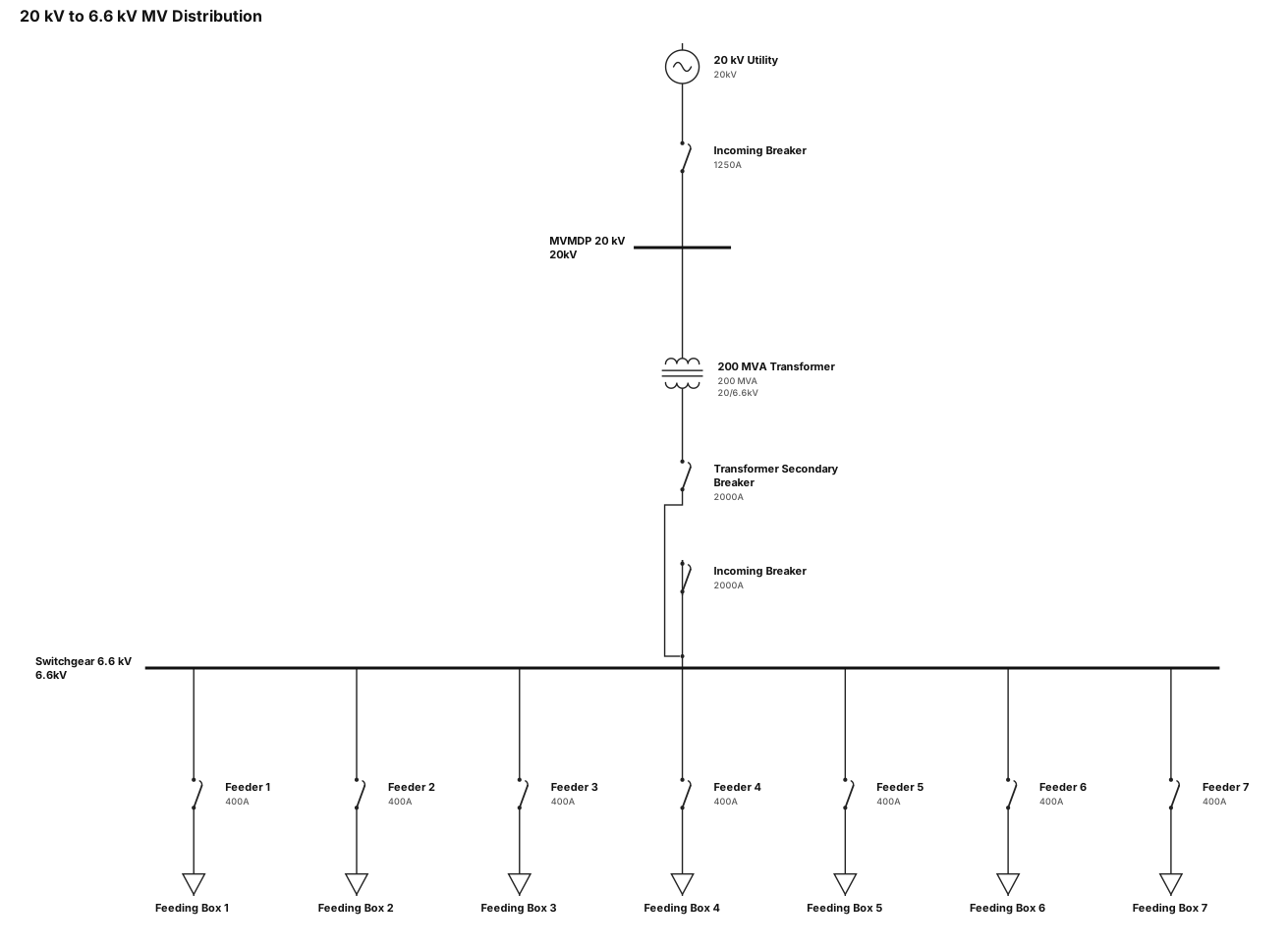
20 KV TO 6,6KV. MVMDP TO SWITCHGEAR 6,6KV. tranformer 200mv. switchgear 1 incoming-7otgoing to feedin box
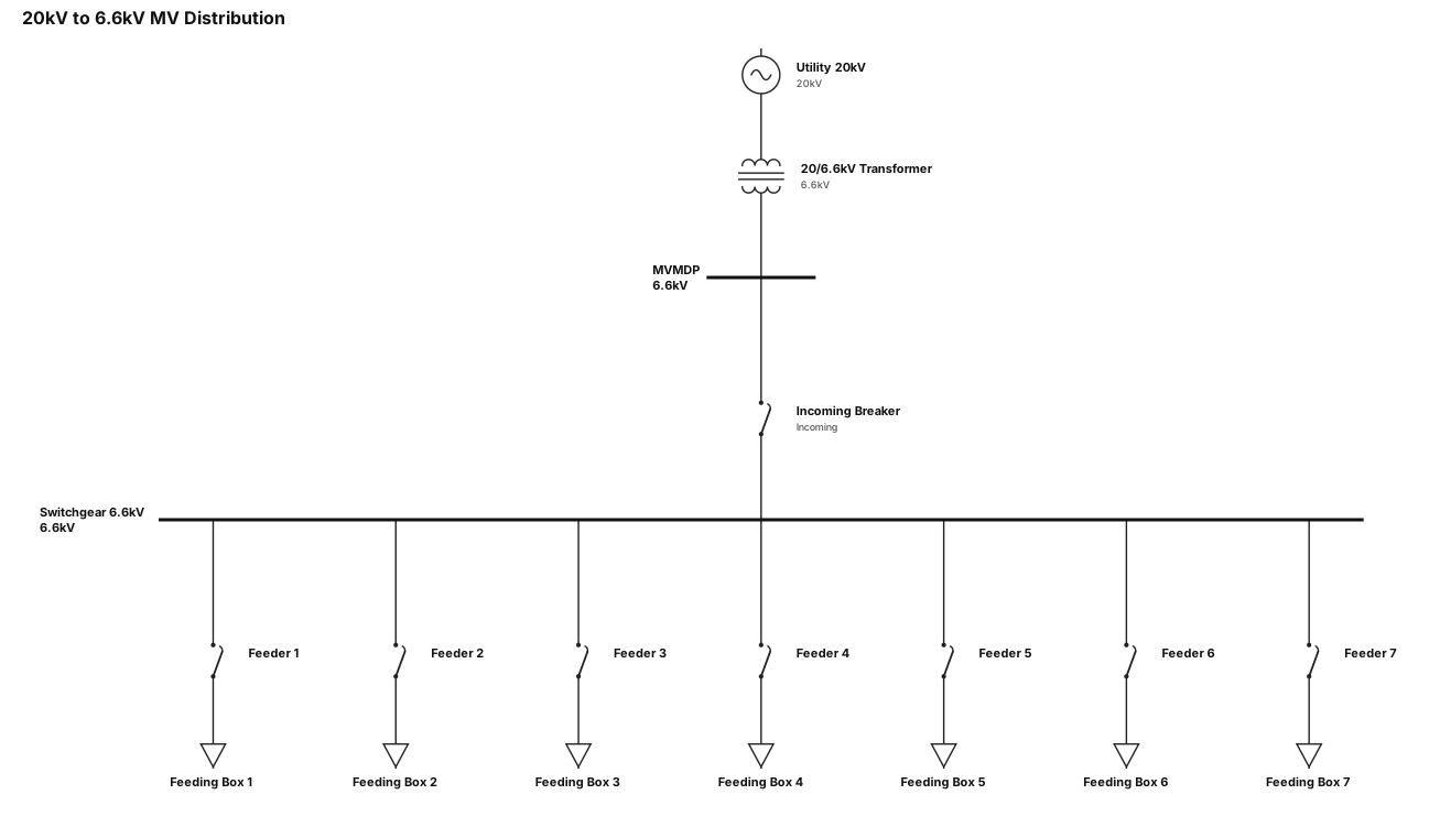
20 KV TO 6,6KV. MVMDP TO SWITCHGEAR 6,6KV. 1incoming-7otgoing to feedin box
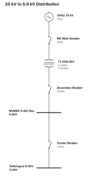
20 KV TO 6,6KV. MVMDP TO SWITCHGEAR 6,6KV
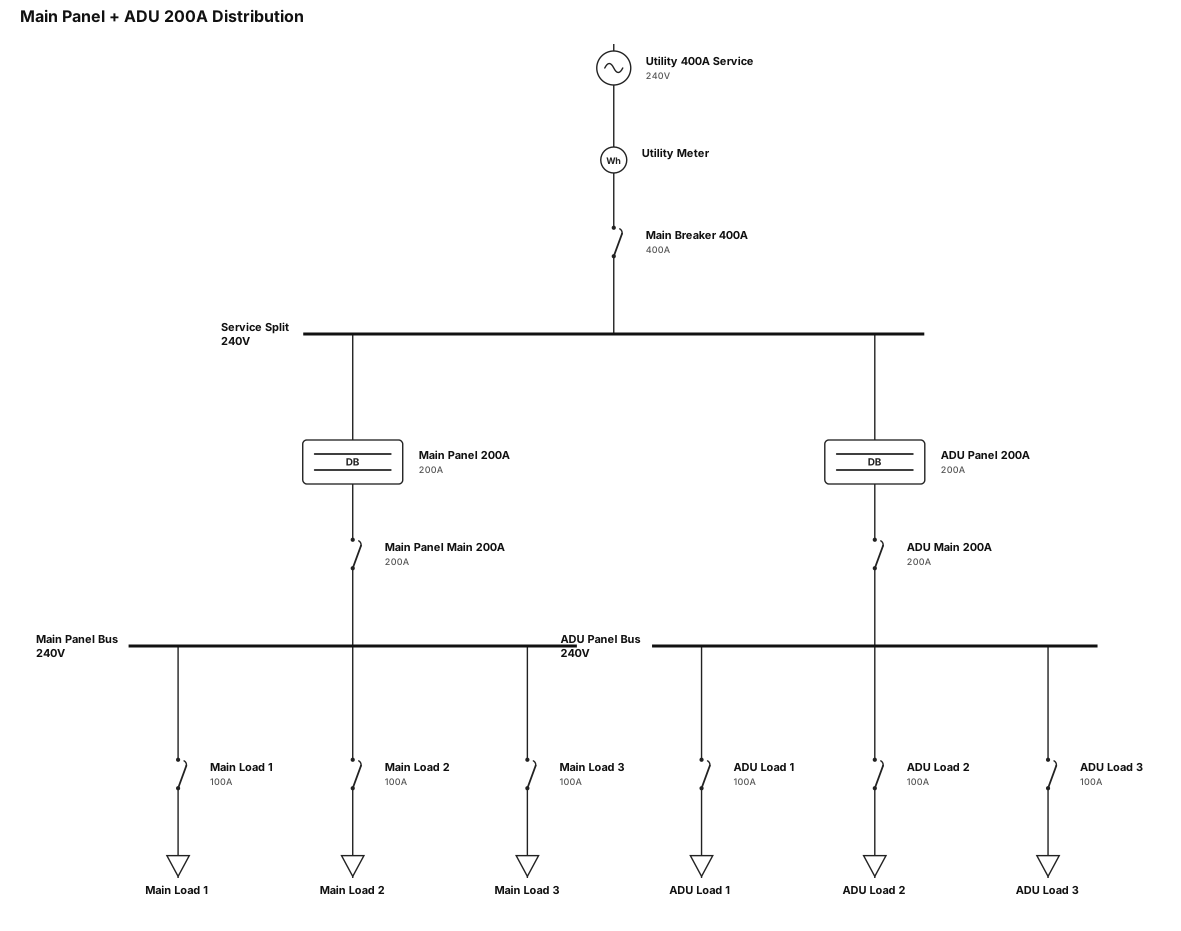
single line drawing for 100Amp to 400Amp 200A on main panel and 200A on the ADU
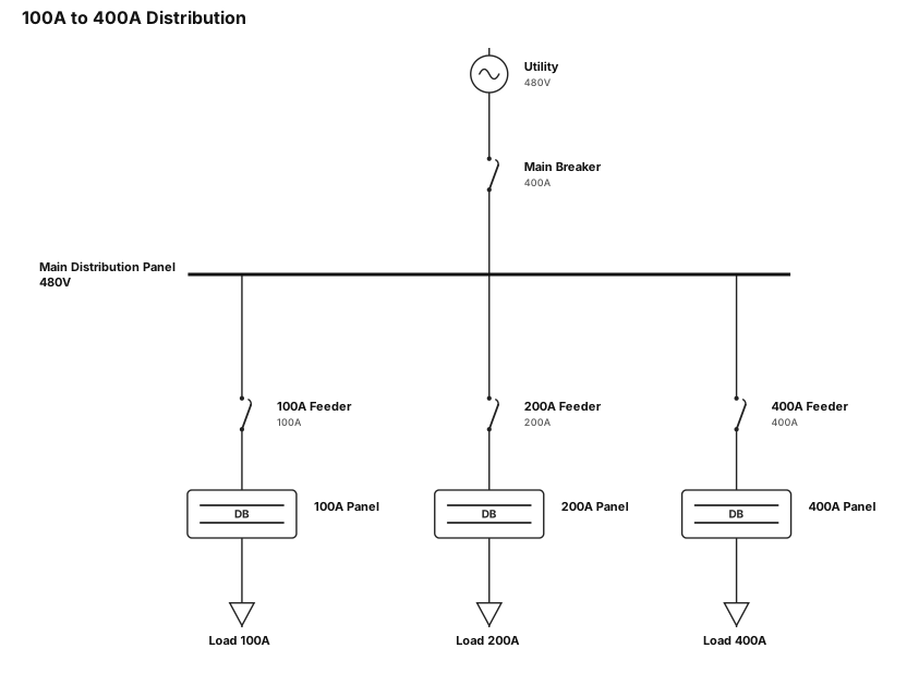
single line drawing for 100Amp to 400Amp
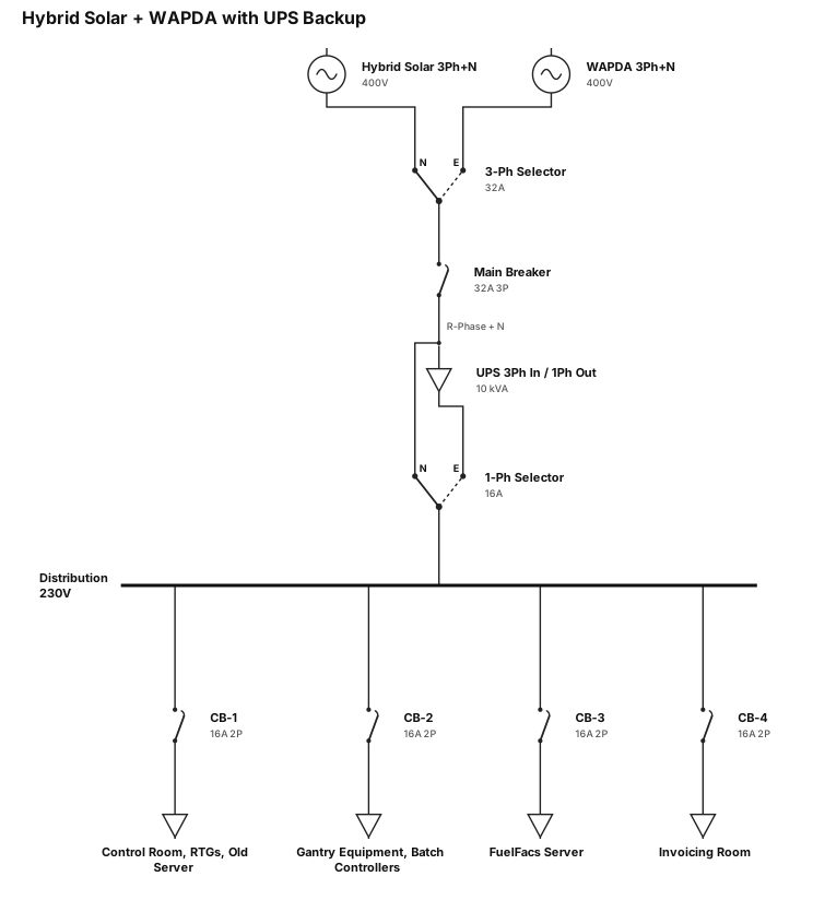
Circuit Description The system comprises two independent 3-phase, 4-wire power sources: Hybrid Solar and WAPDA supply. Both sources are connected to a 3-phase, 4-wire selector/changeover switch, allowing selection of either source for the downstream system. The output of the 3-phase selector is connected to a 3-pole, 32A main circuit breaker. The output of the main breaker is divided into two circuits: UPS Supply: The 3-phase, 4-wire output of the main breaker is connected directly to the input of a 10 kVA UPS. The UPS has a 3-phase input and single-phase output. Normal Supply: The R (Red) phase and Neutral from the main breaker output are connected to one input of a single-phase, 2-source selector/changeover switch. The single-phase output of the 10 kVA UPS is connected to the second input of the same single-phase selector/changeover switch. The selector therefore allows the downstream loads to operate either from the normal R-phase supply or from the UPS output. The output of the single-phase selector is connected to a distribution arrangement comprising four 2-pole, 16A circuit breakers. All four breakers are supplied from the same single-phase source. The connected loads are: CB-1 – 2P, 16A: New Control Room, RTGs and Old Server CB-2 – 2P, 16A: Gantry Equipment including Batch Controllers CB-3 – 2P, 16A: FuelFacs Server CB-4 – 2P, 16A: Invoicing Room In summary: the arrangement provides selectable Hybrid Solar/WAPDA input, with the selected 3-phase supply feeding the 10 kVA UPS and the normal single-phase supply simultaneously available at the final selector. The final selector enables the four critical single-phase load groups to be supplied either through the normal R-phase supply or the UPS output.
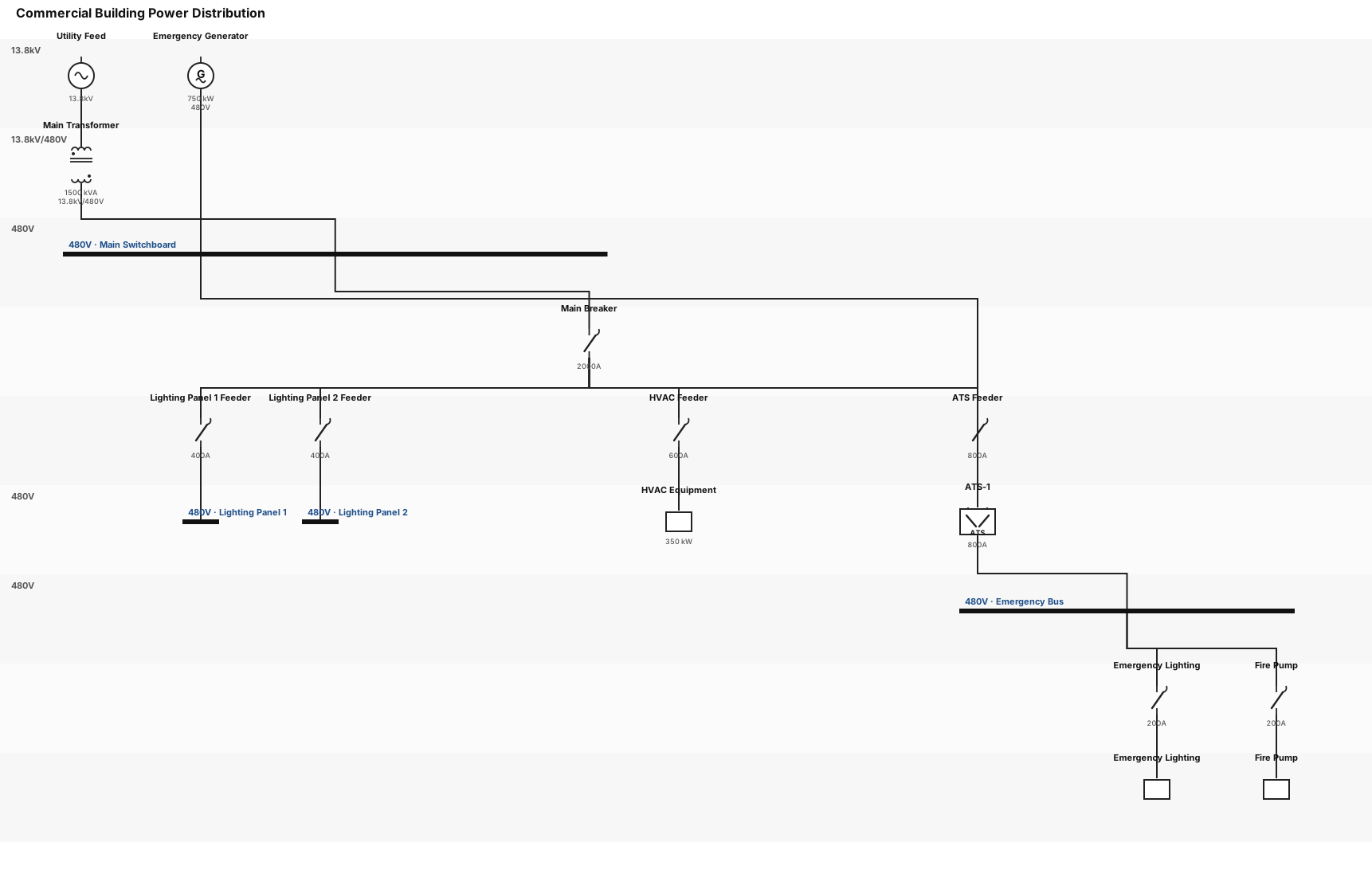
A single-line diagram for a commercial building: utility feed through a main transformer to a 480V switchboard, then to lighting panels, HVAC equipment, and an emergency generator with ATS
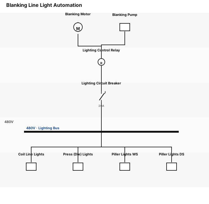
Blanking Line Light Automation system: When the operator starts motor and pump for blanking, the lights on each zone from the coil line, press (Die light) to Piller lights WS and DS will automatically turn on. Then at the end of the shift when the operator stop motor and pump the lights will also switch of automatically.
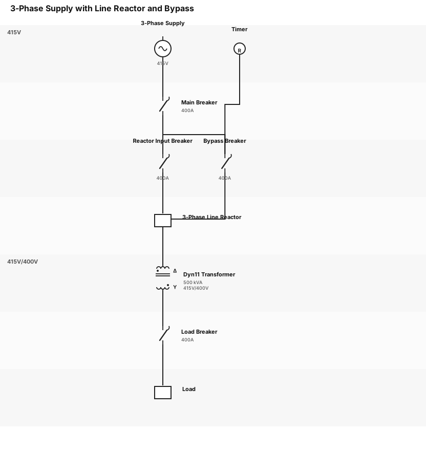
3 Phase Supply -> 3 Phase Line reactor -> Dyn11 Transformer (primary 415V secondary 400V) -> Load. Timer with breaker to bypass 3 Phase Line reactor between 3 Phase Supply and Transformer primary

Main incomer with 20 sub db's
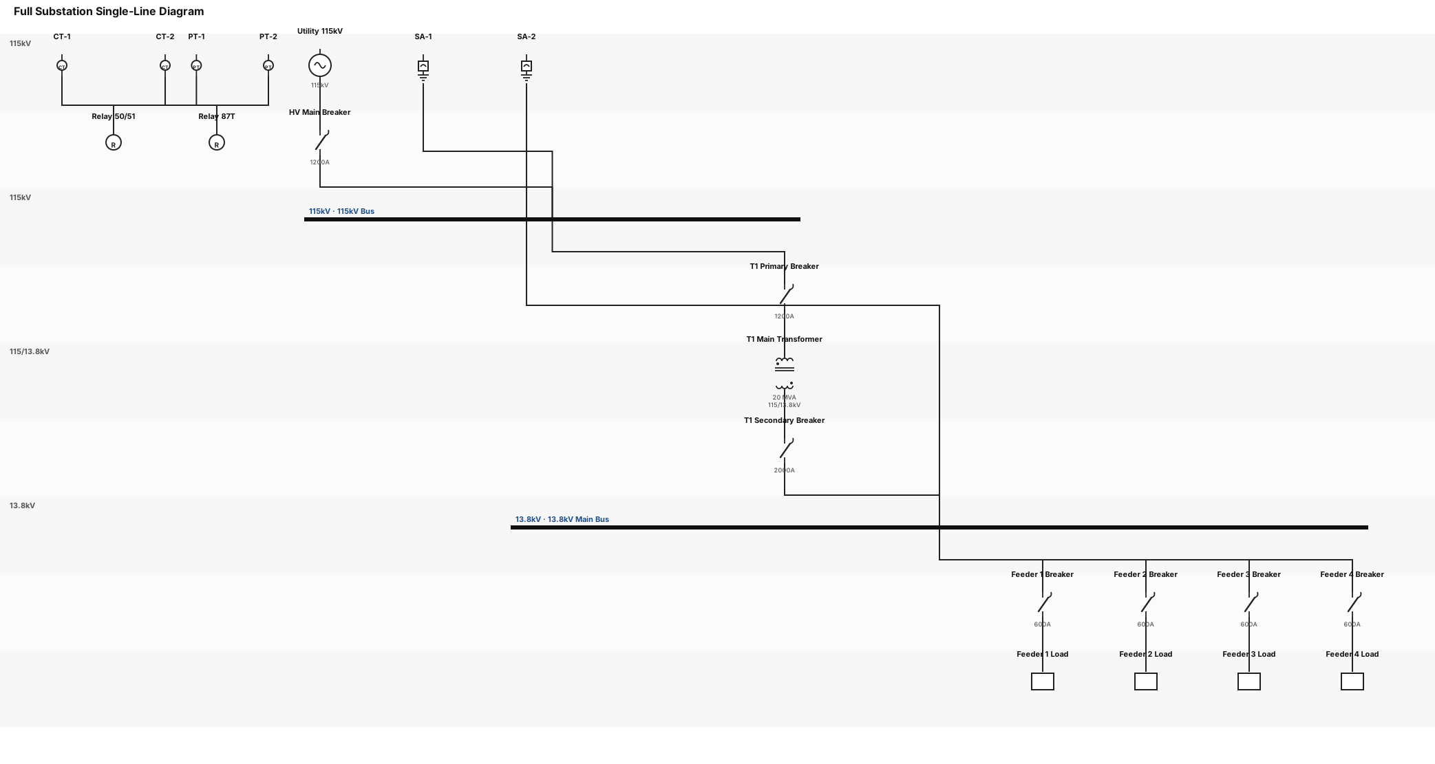
redo the SLD for the full substation following the sequence I gave you
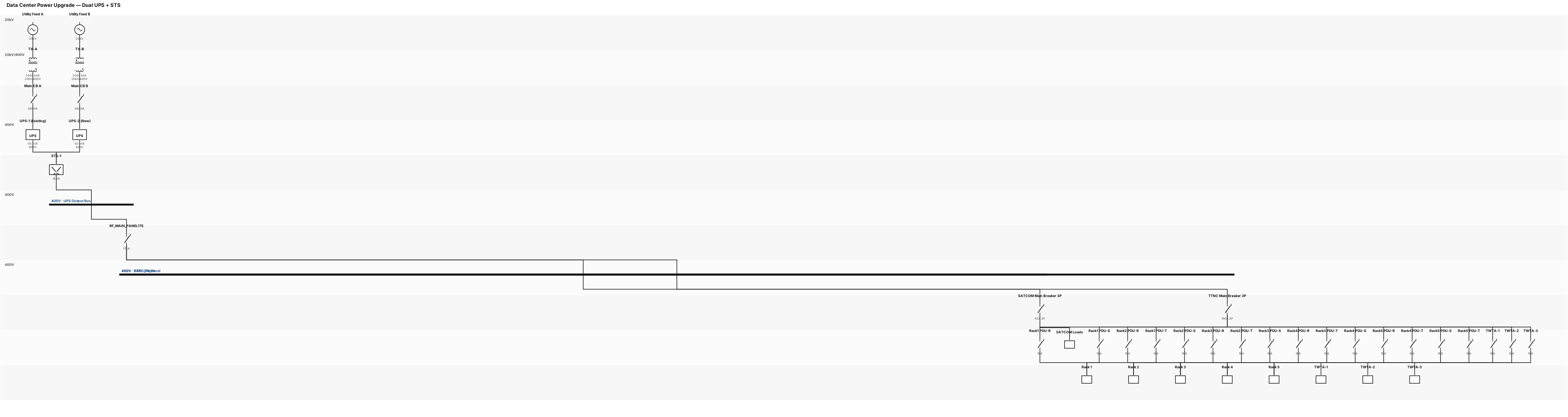
Data center power system with UPS and dual utility feeds. we need diagram for upgrade project, from single ups to dual ups source with STS to output. old line is UPS50KVA to RF_MAIN_PANEL175 then slipt two TTNC_Panel and SATCOM_Panel. from TTNC_Panel distribute to 5 rack with 3 PDU each phase R-S-T, and directly to TWTA1-3 each TWTA using 1 phase. TTNC Panel has 1(one) 3phase Main Breaker input and all output 220V via 16A MiniCircuitBreaker.