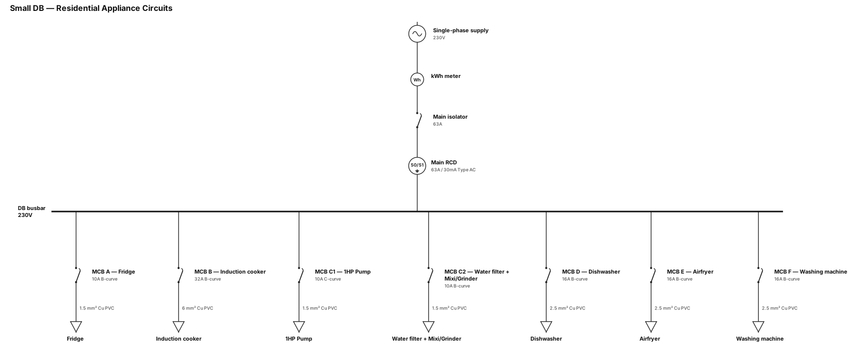
A single-line diagram for a small DB which power,if a single phase db has to acomodate circuits A- fridge, B-Induction cooker, C-1Hp Pump, Water Filter, Mixi, grinder, D-Dishwasher, E-Airfryer,F-Washing machine. water filter will be always on, mixi and grinder maynot be used at the same time. what should be the MCB sizings and wire guage of each phase, neutral and earth at a minimum. should we split Circuit C
NODE ARCHIVE · REAL DIAGRAM BRIEFS
Diagram Examples from Real Visitor Prompts
Browse eligible diagrams shared by FreeDiagram visitors, inspect the exact prompts, and build your own version.
Browse 3297 real creationsCOMMUNITY OUTPUTS · EXACT PROMPTS
All visitor creations
Showing 1513–1536 of 3297. No stock examples or system defaults. Choose a tool, study a real result, then reopen its prompt as your starting point.
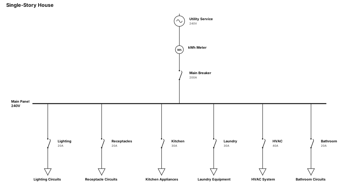
A single-line diagram for a single storye house
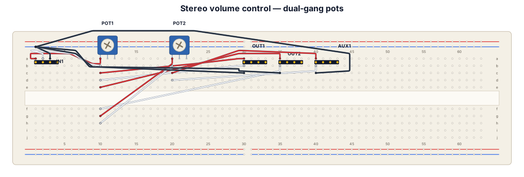
"I have one stereo audio input with L, R and GND. I have two B100K dual-gang potentiometers, two large 3.5mm output ports and one small AUX output. Pot 1 should control the volume of both large ports together. Pot 2 should control only the AUX port. All outputs share audio ground. Show the physical wiring clearly, with each potentiometer's six pins labelled."
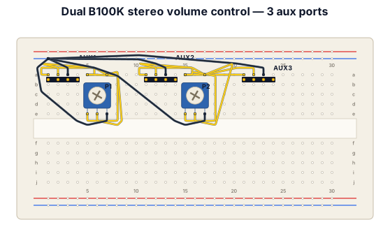
Two B100k stero volume control pot One pot control the volume of one aux port And one volume pot control two aux port
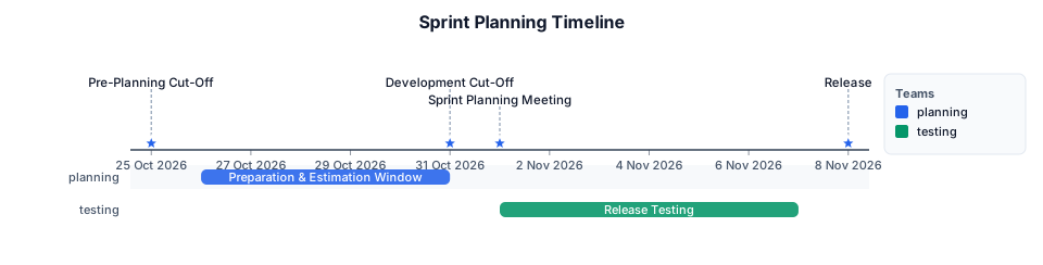
Sprint Planning Timeline Day 25 of previous month (Pre-Planning Cut-Off) All items must meet the agreed Ready for Sprint criteria. Day 26-31 of previous month (Preparation & Estimation Window) Remaining backlog items are estimated collaboratively by the Lead Developer and the assigned engineer. Day 31 of previous month (Development Cut-Off) Day 1 of next month (Sprint Planning Meeting) Day 1-7 of next month (Release Testing) Day 8 of next month (Release) use October-November 2026 as dates
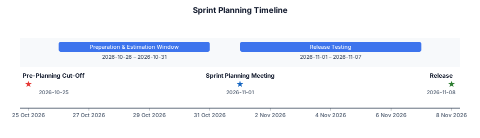
Sprint Planning Timeline Day 25 of previous month (Pre-Planning Cut-Off) All items must meet the agreed Ready for Sprint criteria. Day 26-31 of previous month (Preparation & Estimation Window) Remaining backlog items are estimated collaboratively by the Lead Developer and the assigned engineer. Day 1 of next month (Sprint Planning Meeting) Day 1-7 of next month (Release Testing) Day 8 of next month (Release) use October-November 2026 as dates
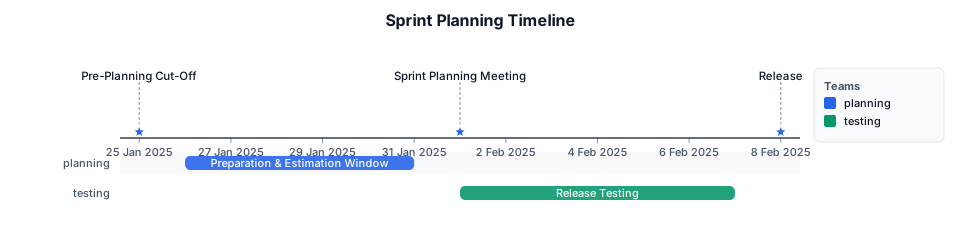
Sprint Planning Timeline Day 25 of previous month (Pre-Planning Cut-Off) All items must meet the agreed Ready for Sprint criteria. Day 26-31 of previous month (Preparation & Estimation Window) Remaining backlog items are estimated collaboratively by the Lead Developer and the assigned engineer. Day 1 of next month (Sprint Planning Meeting) Day 1-7 of next month (Release Testing) Day 8 of next month (Release)
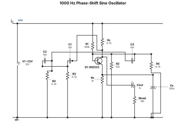
Bir tane transistörlü direnç ve kapasitör kullanan faz kaydırmalı 1000hz sinüs sinyal jeneratörü şeması çiz. Güzel çizmişsin yalnız bu şemada hatalar ve yanlışlar var onları düzelt Bu devre Bu haliyle çalışmaz şemayı tekrar gözden geçir düzenle
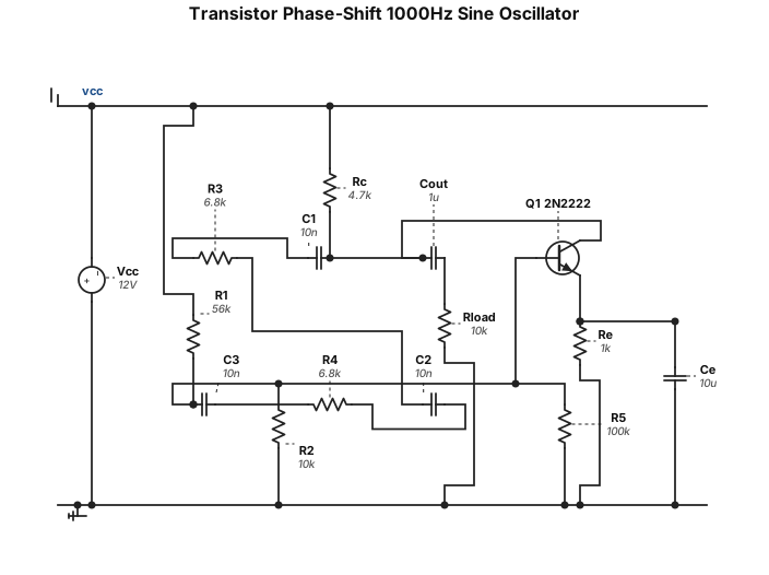
Bir tane transistörlü direnç ve kapasitör kullanan faz kaydırmalı 1000hz sinüs sinyal jeneratörü şeması çiz. Güzel çizmişsin yalnız bu şemada hatalar ve yanlışlar var onları düzelt
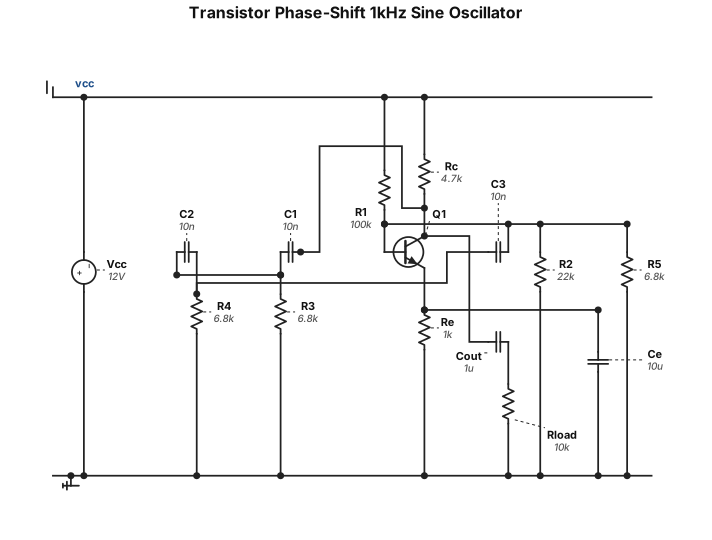
Bir tane transistörlü direnç ve kapasitör kullanan faz kaydırmalı 1000hz sinüs sinyal jeneratörü şeması çiz
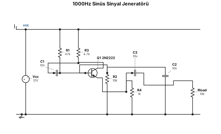
Bir tane transistörlü direnç ve kapasitör kullanan 1000hz sinüs sinyal jeneratörü şeması çiz
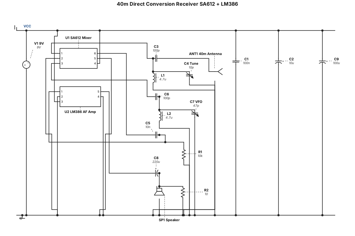
Sa612 ve lm386 kullanan 40 metre bandında direkt konversiyon alıcı radyo şeması çiz
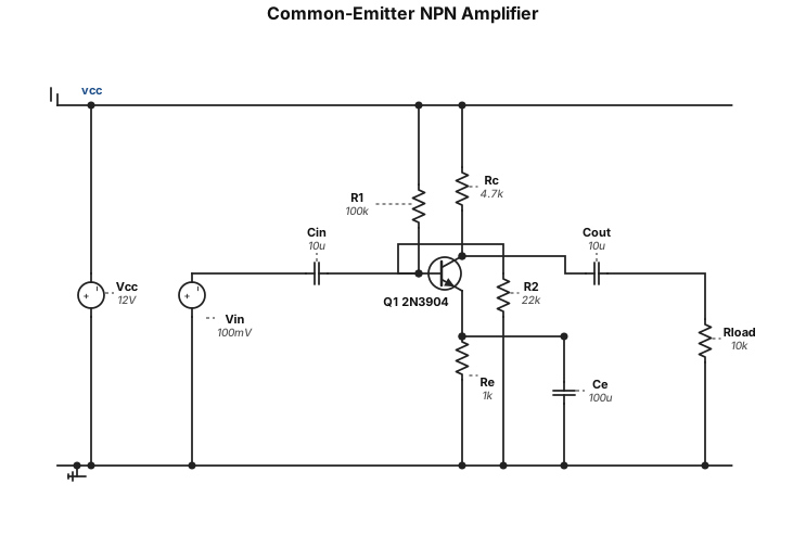
A common-emitter NPN transistor amplifier circuit
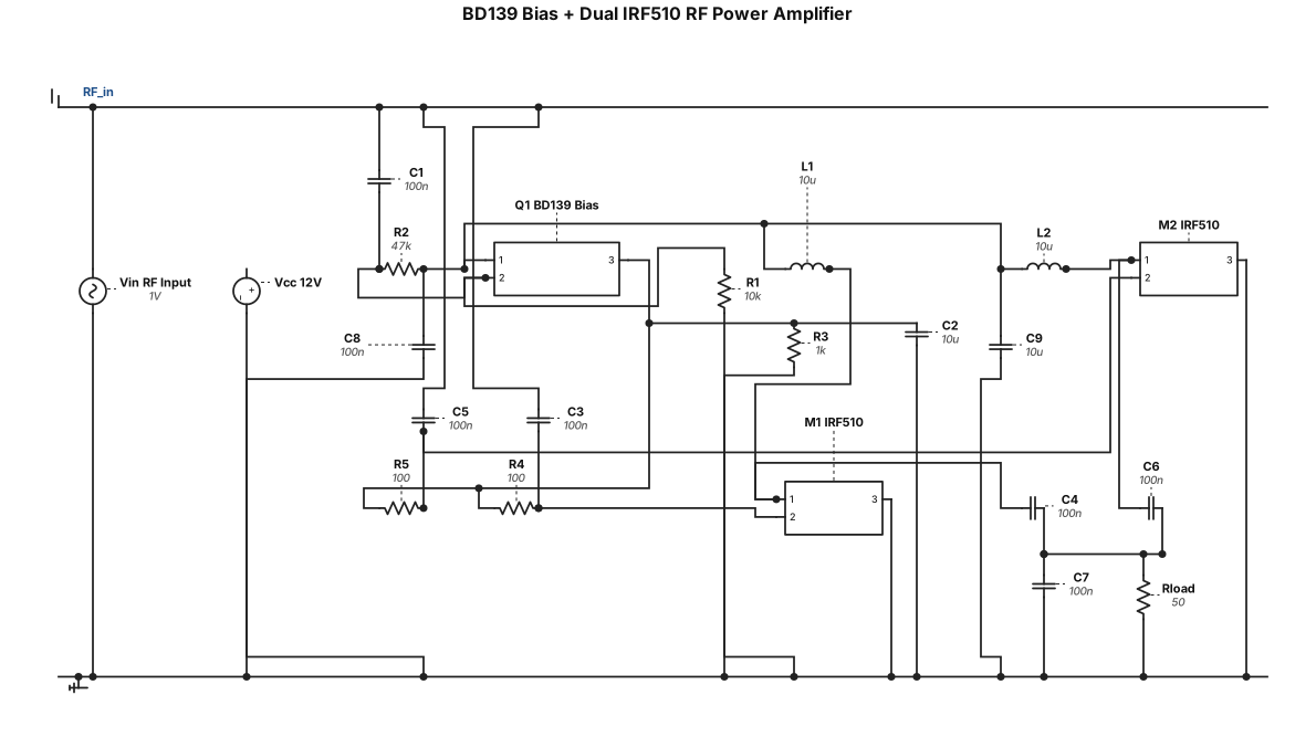
Bana BD139 transistörlü ve 2 mosfet IRF510 MOSFET'li, bias bloklu bir RF güç amplifikatörü şeması çiz şema düzgün olsun öncekine benzemesin
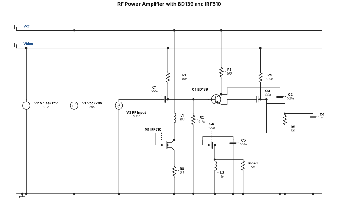
Bana BD139 transistörlü ve IRF510 MOSFET'li, bias bloklu bir RF güç amplifikatörü şeması çiz
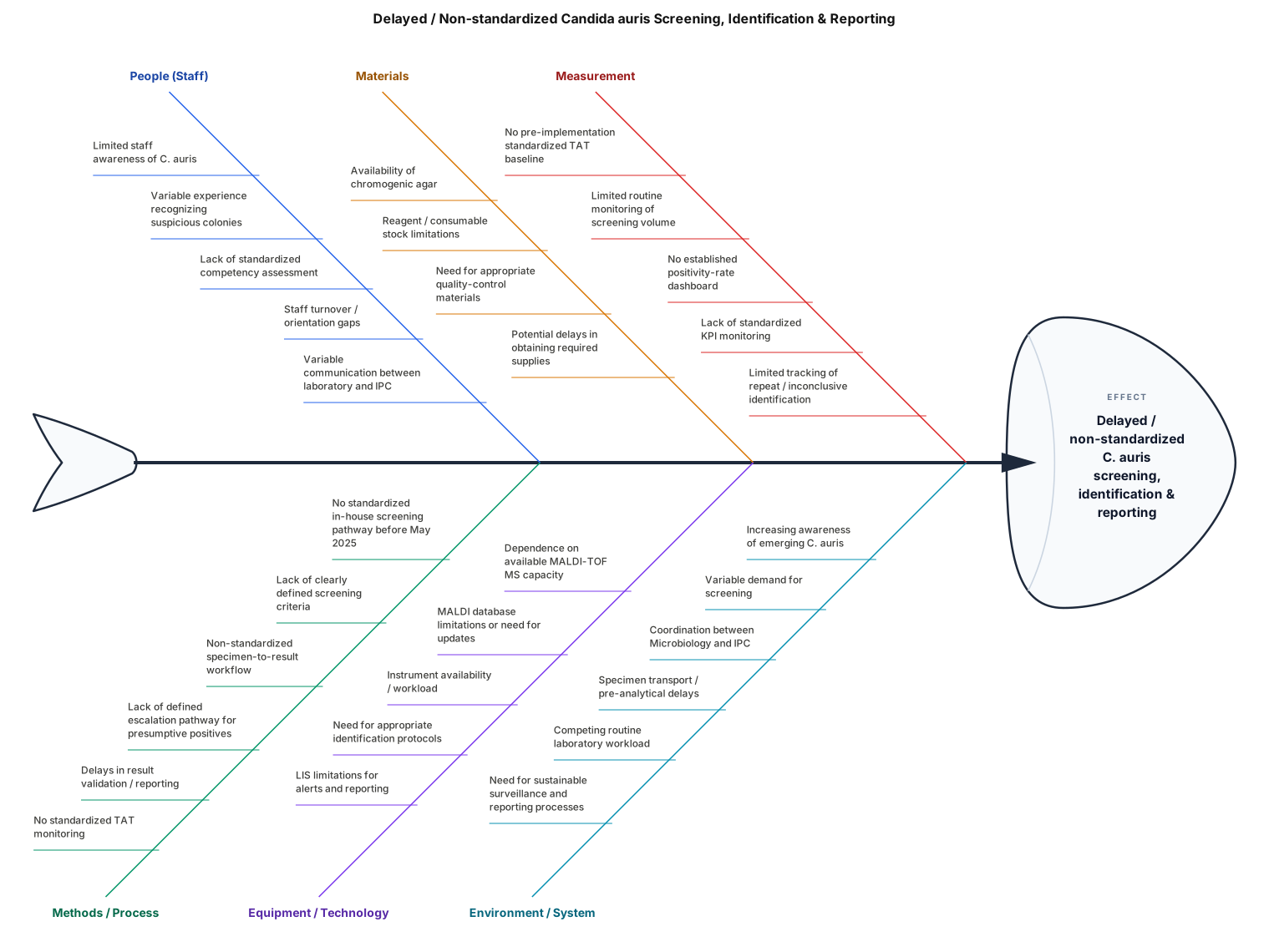
roblem Statement: Delayed / Non-standardized Candida auris Screening, Identification & Reporting 1. People (Staff) Limited staff awareness of C. auris Variable experience in recognizing suspicious colonies Lack of standardized competency assessment Staff turnover/orientation gaps Variable communication between laboratory and IPC 2. Methods / Process No standardized in-house screening pathway before May 2025 Lack of clearly defined screening criteria Non-standardized specimen-to-result workflow Lack of defined escalation pathway for presumptive positives Delays in result validation/reporting No standardized TAT monitoring 3. Materials Availability of chromogenic agar Reagent/consumable stock limitations Need for appropriate quality-control materials Potential delays in obtaining required supplies 4. Equipment / Technology Dependence on available MALDI-TOF MS capacity MALDI database limitations or need for updates Instrument availability/workload Need for appropriate identification protocols LIS limitations for alerts and reporting 5. Measurement No pre-implementation standardized TAT baseline Limited routine monitoring of C. auris screening volume No established positivity-rate dashboard Lack of standardized KPI monitoring Limited tracking of repeat/inconclusive identification 6. Environment / System Increasing awareness of emerging C. auris Variable demand for screening Coordination between Microbiology and IPC Specimen transport/pre-analytical delays Competing routine laboratory workload Need for sustainable surveillance and reporting processes
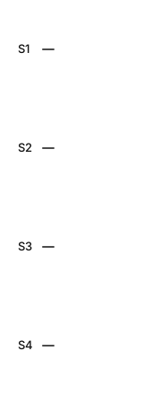
Create a digital logic gate diagram for a combinational circuit with 4 inputs ($S_1, S_2, S_3, S_4$) and 2 outputs ($M$ and $L$). Use NOT, AND, and OR gates.Here are the exact Boolean equations to implement:Output M = $(S_1 \cdot S_2 \cdot S_3) + (S_1 \cdot S_2 \cdot S_4) + (S_1 \cdot S_3 \cdot S_4) + (S_2 \cdot S_3 \cdot S_4)$Output L = $(S_1 \cdot S_2 \cdot \overline{S_3}) + (S_1 \cdot S_3 \cdot \overline{S_2}) + (S_1 \cdot S_4 \cdot \overline{S_2}) + (S_2 \cdot S_3 \cdot \overline{S_4}) + (S_2 \cdot S_4 \cdot \overline{S_3}) + (S_3 \cdot S_4 \cdot \overline{S_1})$Draw the circuit schematic clearly showing the connections between the switches, the inverter gates, the 3-input AND gates, and the OR summation gates for both outputs.
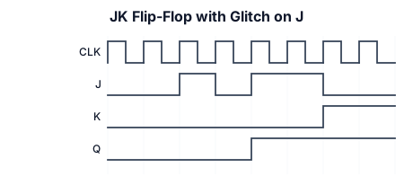
jk with glitch in one side only
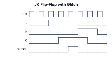
jk with glitch
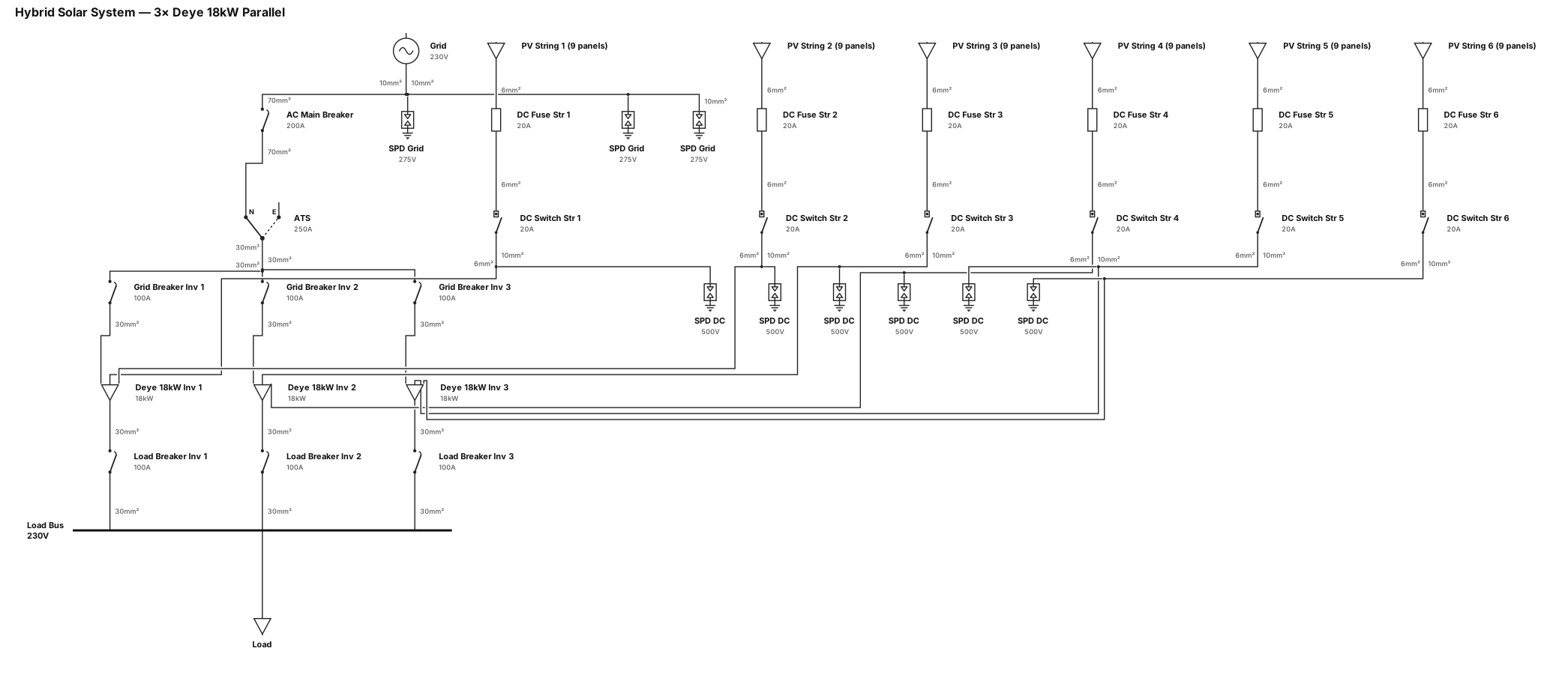
single line diagram of hybrid solar system with 3pcs Deye 18kw single phase inverter in parallel, 3pcs 100a ac breaker load side and 3pcs 100a ac breaker grid side using 30mm wire and 3pcs 275v spd using 10mm wire grid side 1 pc 200a ac main breaker using 70mm wire and 250a ATS, 6 strings with 9 panels using 20a dc fuse and 20a dc breaker switch with 6mm wire with 6pcs 500v spd using 10mm ground wire
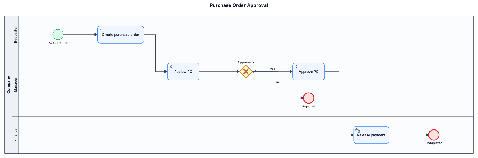
A BPMN diagram of a purchase-order approval process across three lanes: requester submits a PO, manager reviews and approves or rejects, finance releases payment
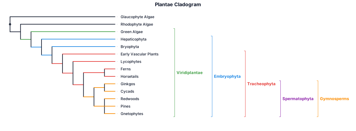
A cladogram with square branches of the plantae clade showing glaucophyte algae as an outgroup, then rhodophyte algae (red algae), then green algae - which are separate branches, then hepaticophyta (liverworts), bryophta (mosses), then early vascular plants, then lycophytes, then a branch that splits into ferns and horsetails, then a clade made up of the gymnosperms, and angiosperms. Within the gymnosperms there are two groups - the ginkos and cycads and another group the redwoods, pines and gnetophytes which originate in a polytomy
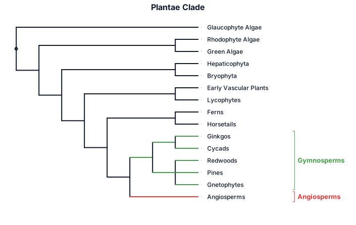
A cladogram with square branches of the plantae clade showing glaucophyte algae as an outgroup, then rhodophyte algae (red algae), then green algae, then hepaticophyta (liverworts), bryophta (mosses), then early vascular plants, then lycophytes, then a branch that splits into ferns and horsetails, then a clade made up of the gymnosperms, and angiosperms. Within the gymnosperms there are two groups - the ginkos and cycads and another group the redwoods, pines and gnetophytes which originate in a polytomy
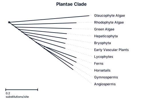
A phylogenetic tree with square branches of the plantae clade showing glaucophyte algae as an outgroup, then rhodophyte algae (red algae), then green algae, then hepaticophyta (liverworts), bryophta (mosses), then early vascular plants, then lycophytes, then a branch that splits into ferns and horsetails, then a clade made up of the gymnosperms, and angiosperms. Within the gymnosperms there are two groups - the ginkos and cycads and another group the redwoods, pines and gnetophytes which originate in a polytomy