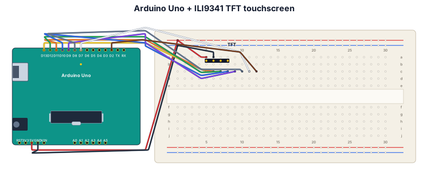
Arduino Uno + F260301 ILI9341 TFT touchscreen. Display SPI: SCK D13, MOSI D11, MISO D12, CS D10, DC D9, RESET D8. Touch SPI: T_CLK D13, T_DIN D11, T_DO D12, T_CS D7, T_IRQ D2.
NODE ARCHIVE · REAL DIAGRAM BRIEFS
Diagram Examples from Real Visitor Prompts
Browse eligible diagrams shared by FreeDiagram visitors, inspect the exact prompts, and build your own version.
Browse 3297 real creationsCOMMUNITY OUTPUTS · EXACT PROMPTS
All visitor creations
Showing 1609–1632 of 3297. No stock examples or system defaults. Choose a tool, study a real result, then reopen its prompt as your starting point.
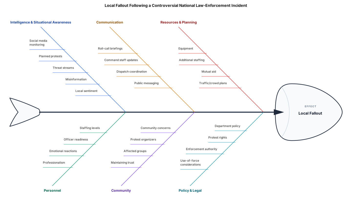
Create a professional fishbone (Ishikawa) diagram for a law-enforcement leadership presentation. The problem/effect at the head of the fish should be: “Local Fallout Following a Controversial National Law-Enforcement Incident.” The purpose is to show what a police sergeant should proactively consider to get ahead of potential problems rather than reacting after they occur. Use these main branches: - Intelligence & Situational Awareness — social media, planned protests, threats, misinformation, local sentiment - Personnel — staffing, officer readiness, emotional reactions, professionalism - Communication — roll-call briefings, command staff, dispatch, public messaging - Community — community concerns, protest organizers, affected groups, maintaining trust - Resources & Planning — equipment, additional staffing, mutual aid, traffic/crowd plans - Policy & Legal Considerations — department policy, protest rights, enforcement authority, use-of-force considerations Make it visually clean and appropriate for a police PowerPoint presentation. Keep the wording short enough to be easily read on a presentation slide. make the words big to read in the rear of the classroom
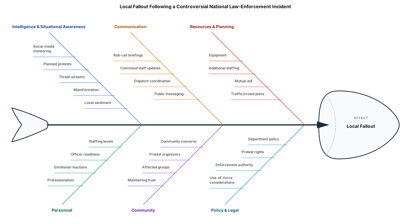
Create a professional fishbone (Ishikawa) diagram for a law-enforcement leadership presentation. The problem/effect at the head of the fish should be: “Local Fallout Following a Controversial National Law-Enforcement Incident.” The purpose is to show what a police sergeant should proactively consider to get ahead of potential problems rather than reacting after they occur. Use these main branches: - Intelligence & Situational Awareness — social media, planned protests, threats, misinformation, local sentiment - Personnel — staffing, officer readiness, emotional reactions, professionalism - Communication — roll-call briefings, command staff, dispatch, public messaging - Community — community concerns, protest organizers, affected groups, maintaining trust - Resources & Planning — equipment, additional staffing, mutual aid, traffic/crowd plans - Policy & Legal Considerations — department policy, protest rights, enforcement authority, use-of-force considerations Make it visually clean and appropriate for a police PowerPoint presentation. Keep the wording short enough to be easily read on a presentation slide.
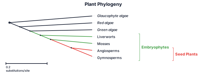
(glaucophyte algae (red algae (green algae (liverworts (mosses (angiosperms, gymnosperms))))))
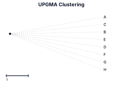
A: (1,0,1,0,0,0,0 B: (1,1,0,1,1,1,1) C: (1,0,1,0,0,0,0) D: (1,1,0,1,0,0,0) E: (1,1,0,1,1,1,1) F: (1,1,0,1,1,0,0) G: (1,1,0,0,0,0,0) H: (1,1,0,1,1,1,0)
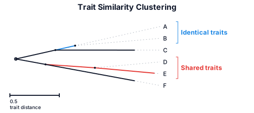
A: (1,1,1,0,0) B: (1,1,1,0,0) C: (0,0,1,1,1) D: (0,0,1,1,1 E: (1,0,1,0,0) F: (0,0,1,0,1)
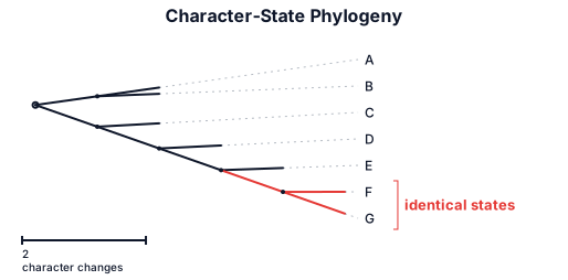
A: (1,0,0,0,0,0) B: (1,1,0,0,0,0) C: (1,1,1,0,0,0) D: (1,1,1,1,0,0) E: (1,1,1,1,1,0) F: (1,1,1,1,1,1) G: (1,1,1,1,1,1)
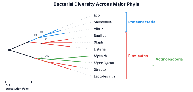
Bacterial diversity across the major phyla including Firmicutes, Proteobacteria, and Actinobacteria
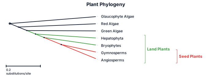
can you help me generate a phylogenetic tree that shows relationships among the mosses, ferns, horsetails, gymnosperms, angiosperms, glaucophyte algae, green algae, and red algae. Glaucophyte algae branches off first and is an outgroup. Then rhodophyta (red algae) branches off. Then green algae branches off. Next hepatophyta (liverworts), then bryophytes (mosses), finally the clade that shares the most recent common ancestor is gymnosperms and angiosperms.
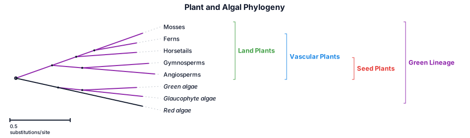
can you help me generate a phylogenetic tree that shows relationships among the mosses, ferns, horsetails, gymnosperms, angiosperms, glaucophyte algae, green algae, and red algae
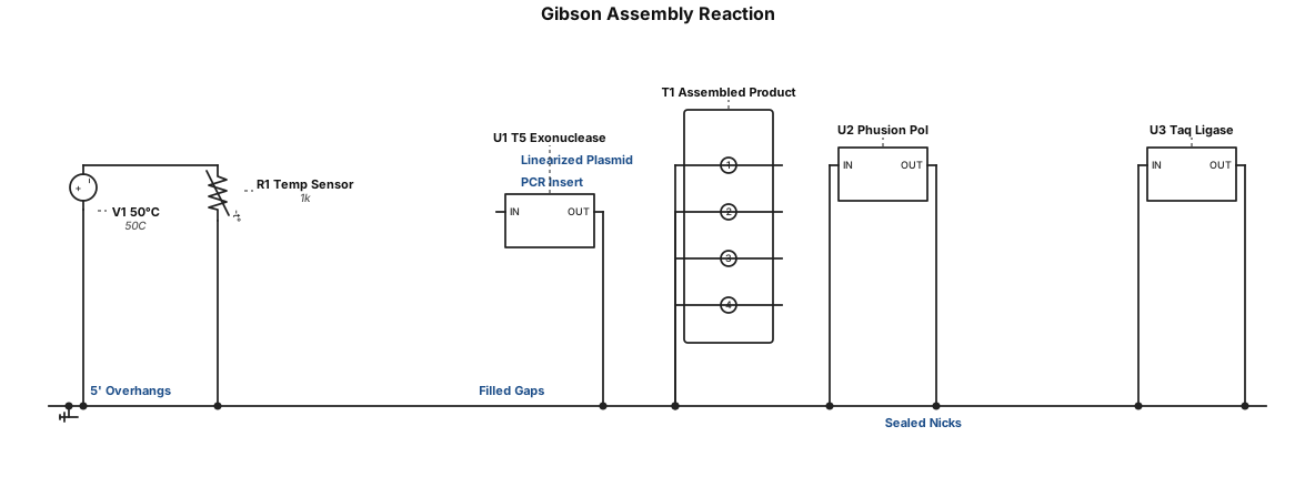
Homology-Based Cloning: Gibson Assembly First described by Dr. Daniel Gibson and colleagues, 2009 Requires homology between neighbouring fragments created via PCR 25–40 bp homology region required Reaction: master mix + PCR insert + linearized plasmid 50 °C, 15–60 min Mechanism: (1) exonuclease chews back 5′ ends → (2) complementary single-stranded overhangs anneal → (3) DNA polymerase fills gaps → (4) DNA ligase seals nicks Commonly performed with NEB (New England Biolabs) enzymes
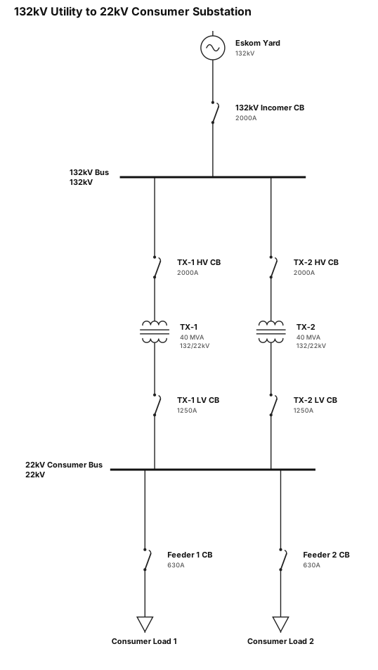
132KV from utility, eskom yard with 132KV:22kv stepdown transformers, CONSUMER SUBSTATION
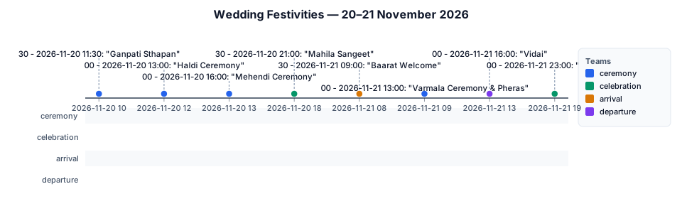
20 November 2026 10:30am -Ganpati Sthapan 12:00pm - Haldi Ceremony – (dress code green) 1:00 pm - Mehendi Ceremony – until approximately 4:00 6:30 pm - Mahila Sangeet 21 November 2026 8:30 AM – Baarat Welcome 9:00 AM – Varmala Ceremony & Pheras 1:00 PM to 4:00 PM – Vidai 7:00 PM – Reception Make an image or a video of the timeline

Business Analysis from start to finish
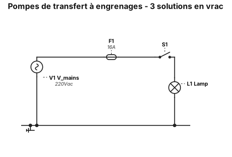
Trois pompes de transfert de type à engrenages sont situées sur un collecteur commun et un bloc de montage à l'avant du tiroir des solutions en vrac. Chaque pompe est dédiée à l'une des solutions en vrac. Les connexions comportent une indication de sens sur le bloc de montage et un code couleur par solution. Une vanne de régulation pour chaque solution en vrac est montée sur un autre collecteur afin d'empêcher les liquides de s'écouler des bouteilles du client à travers les pompes avant le transfert souhaité. Ces vannes sont parfois appelées « vannes de haute altitude », car la pression interne des bouteilles de solutions en vrac expédiées vers des altitudes plus élevées aurait tendance à forcer le liquide à travers les pompes avant le début normal du transfert. Lorsque la pompe fonctionne, la vanne de régulation s'ouvre et permet au liquide de circuler librement dans le système entre la bouteille du client et le réservoir intégré. Le collecteur de la pompe comprend des points de montage pour chaque pompe, des joints pour l'entrée et la sortie de la pompe, ainsi que des récepteurs filetés pour chacun des raccords de tubes d'entrée et de sortie. Il n'y a aucune interconnexion entre les solutions. Bien que le bloc de montage de la pompe soit qualifié de « collecteur » ou de système à passages multiples, il ne contient en réalité que six passages directs entre les raccords de tubes et l'entrée et la sortie de la pompe.
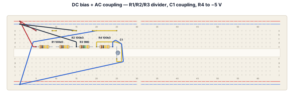
This circuit combines DC biasing with an AC signal and then couples that signal through a capacitor. The two power supplies create three rails: +10 V, 0 V (common ground), and −5 V. The signal generator is referenced to the 0 V rail and sends its AC signal through R2 = 100 kΩ to node A. R1 = 100 kΩ connects node A to +10 V, while R3 = 1 MΩ connects A to 0 V. These resistors provide a DC bias for node A. C1 = 1 nF is connected between A and B. It acts as a coupling capacitor: it blocks the DC voltage at A but allows changing/AC signals to pass to B. R4 = 100 kΩ connects node B to −5 V, setting the DC level on the B side of the capacitor. Node C is simply the −5 V rail. So, in simple terms: the signal generator causes node A to vary around a positive DC bias; C1 transfers the AC variation to node B while separating the two DC levels; node B therefore varies around a DC level determined by the −5 V supply and R4. For a logbook, you could write: The circuit uses R1, R2 and R3 to bias the input signal at node A. The AC component is coupled through the 1 nF capacitor C1 to node B, while DC is blocked. R4 connects node B to the −5 V supply, establishing a different DC operating level on the output side. All equipment uses the same 0 V reference.
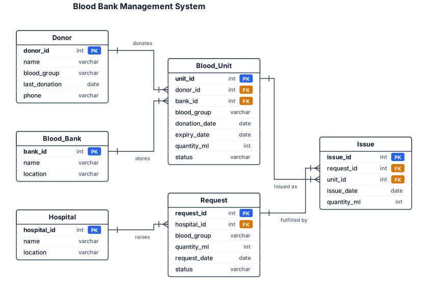
Blood Bank Management System Design a database tracking Donors (with Blood_Group, last donation date) who make Donations (date, quantity) stored as Blood_Units in a Blood_Bank inventory categorized by blood group and expiry date. Hospitals raise Requests for specific blood groups/quantities, fulfilled by matching available units — track Issue records linking a request to specific unit(s)
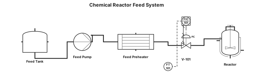
A P&ID for a chemical reactor feed system: feed tank, centrifugal pump, flow transmitter with a PID controller driving a control valve, and a heat exchanger before the reactor inlet
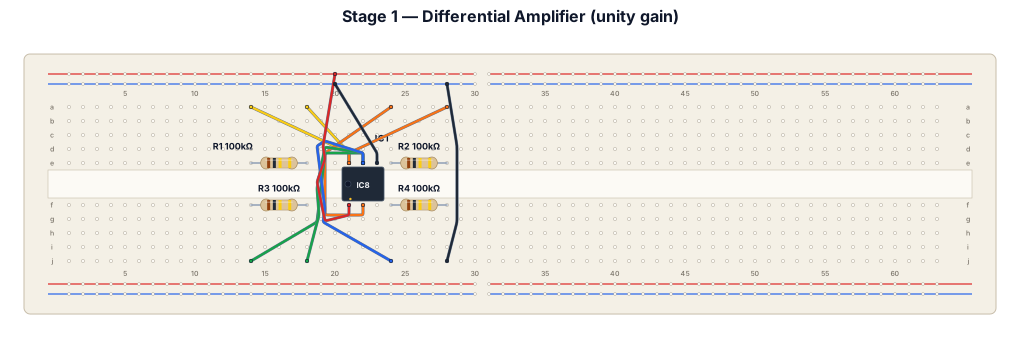
3. Stage 1 — Differential Amplifier Computes (setpoint − feedback) with unity gain. All four resistors: 100 kΩ. From To Component Feedback signal (sensor) IC1 pin 2 (−) via R1 (100kΩ) IC1 pin 6 (output) IC1 pin 2 (−) via R2 (100kΩ) — feedback Setpoint signal IC1 pin 3 (+) via R3 (100kΩ) IC1 pin 3 (+) Ground via R4 (100kΩ) IC1 pin 7 +15V rail IC1 pin 4 −15V rail
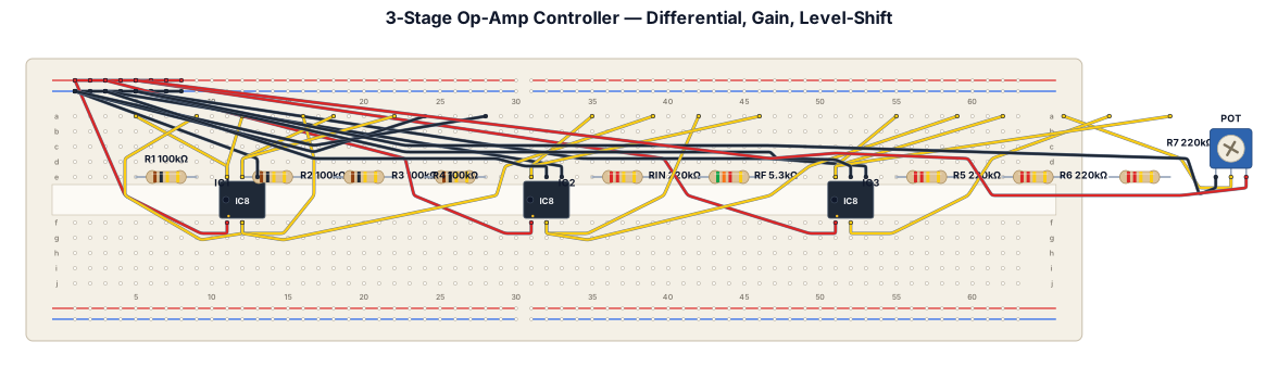
3. Stage 1 — Differential Amplifier Computes (setpoint − feedback) with unity gain. All four resistors: 100 kΩ. From To Component Feedback signal (sensor) IC1 pin 2 (−) via R1 (100kΩ) IC1 pin 6 (output) IC1 pin 2 (−) via R2 (100kΩ) — feedback Setpoint signal IC1 pin 3 (+) via R3 (100kΩ) IC1 pin 3 (+) Ground via R4 (100kΩ) IC1 pin 7 +15V rail IC1 pin 4 −15V rail 4. Stage 2 — Gain Amplifier (Kc) Inverting amplifier, Kc = Rf/Rin ≈ 0.0241. From To Component IC1 pin 6 (Stage 1 output) IC2 pin 2 (−) via Rin (220kΩ) IC2 pin 6 (output) IC2 pin 2 (−) via Rf (~5.3kΩ) — feedback IC2 pin 3 (+) Ground direct IC2 pin 7 +15V rail IC2 pin 4 −15V rail 5. Stage 3 — Level-Shift Summing Amplifier Adds the hover offset back in (double inversion from Stages 2+3 restores the correct sign). From To Component IC2 pin 6 (Stage 2 output) IC3 pin 2 (−) via R (220kΩ) Potentiometer wiper (tuned to −2.4565V) IC3 pin 2 (−) via R (220kΩ) IC3 pin 6 (output) IC3 pin 2 (−) via R (220kΩ) — feedback IC3 pin 3 (+) Ground direct IC3 pin 7 +15V rail IC3 pin 4 −15V rail Potentiometer: one end −15V rail Potentiometer: other end Ground 6. Assembly Order 1) Wire +15V, −15V, and a common ground bus across the whole board before placing any IC. 2) Insert and wire Stage 1 completely; verify with a multimeter before continuing. 3) Insert and wire Stage 2, feeding from Stage 1's output. 4) Insert and wire Stage 3, feeding from Stage 2's output and the potentiometer reference. 5) With the board powered but NOT yet connected to the DAQ, tune the potentiometer wiper to exactly −2.4565V using a multimeter. 6) Ground both Stage 1 inputs (setpoint and feedback) and confirm the final output reads close to +2.4565V — this validates the whole chain end-to-end. 7) Only once this checks out, connect Stage 1's inputs to the DAQ's ADC channels (setpoint, feedback) and Stage 3's output to the DAC channel feeding the kitticopter simulation.
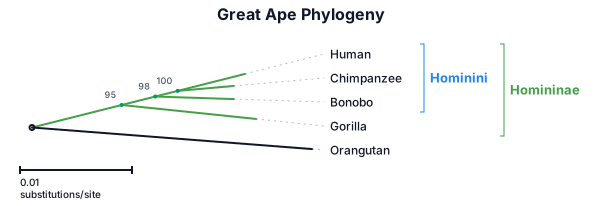
A phylogenetic tree of the great apes: humans, chimpanzees, bonobos, gorillas, and orangutans, with branch lengths and bootstrap support values
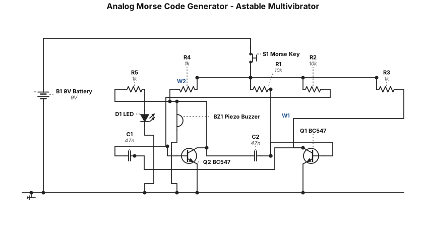
Generate a complete, accurate electronic schematic for a simple Analog Morse Code Generator using a two-transistor collector-coupled astable multivibrator. Use two BC547 NPN transistors, a 9V DC battery, two 10kΩ base resistors, two 1kΩ collector resistors, two 47nF timing capacitors, one push button to enable/disable the oscillator, one passive piezo buzzer for audio output, and one LED with a 1kΩ current-limiting resistor as a visual indicator. Clearly show the BC547 collector, base, and emitter pins and label every component value. Show the cross-coupling connections between the collector of Q1 and the base of Q2 through C1, and the collector of Q2 and the base of Q1 through C2. Connect both emitters to ground and the resistor networks to +9V. The push button should control the oscillator/output. Use standard electronic schematic symbols, clearly labeled +9V and GND rails, and make every electrical connection explicit. Do not use Arduino, microcontrollers, IC timers, or sensors. This is for a college Analog Electronics mini-project and the schematic must be suitable for breadboard construction.
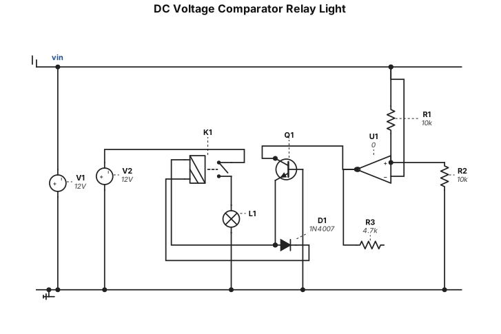
dc voltage comparator relay to turn on light
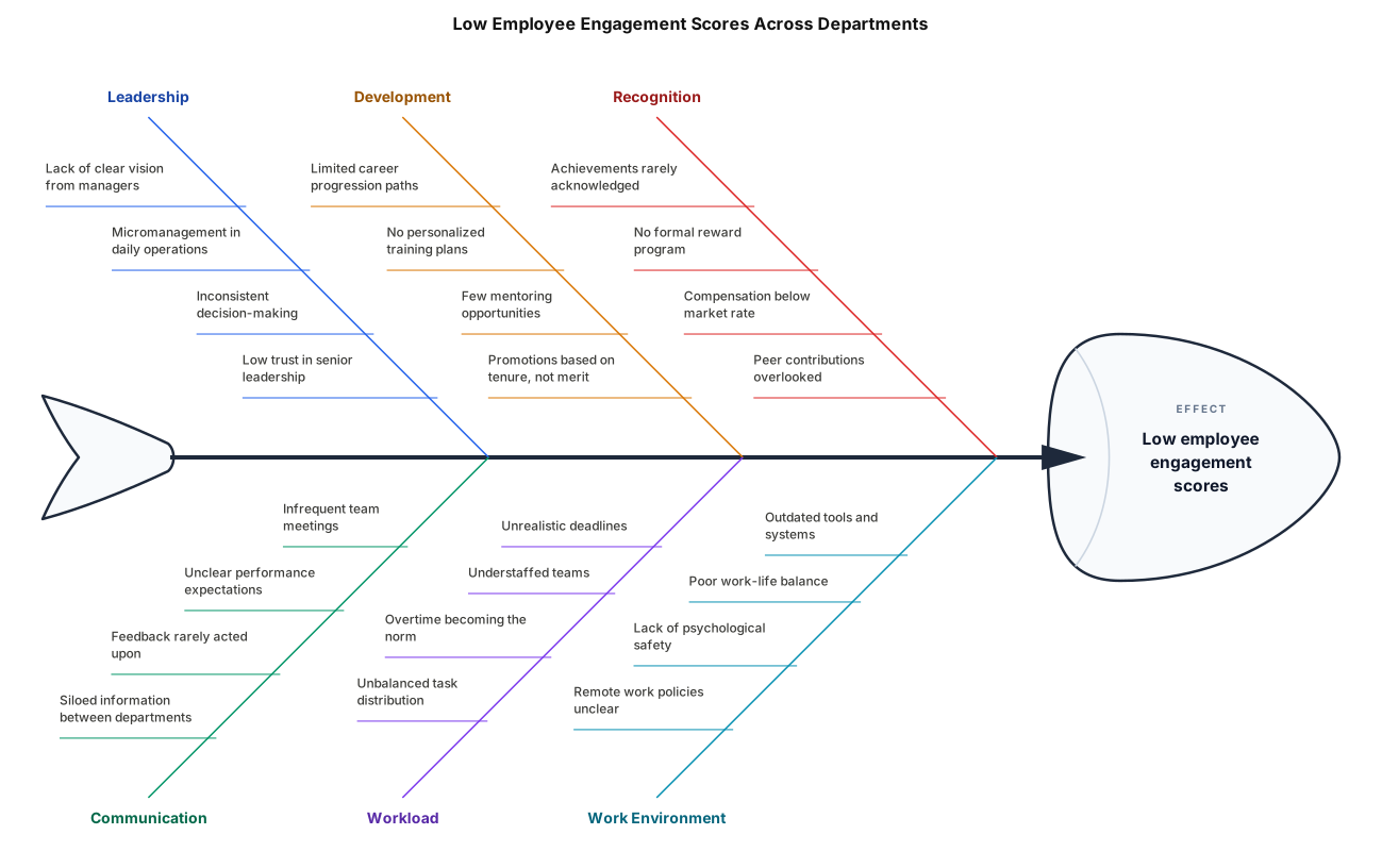
Cause-and-effect diagram for low employee engagement scores across three departments