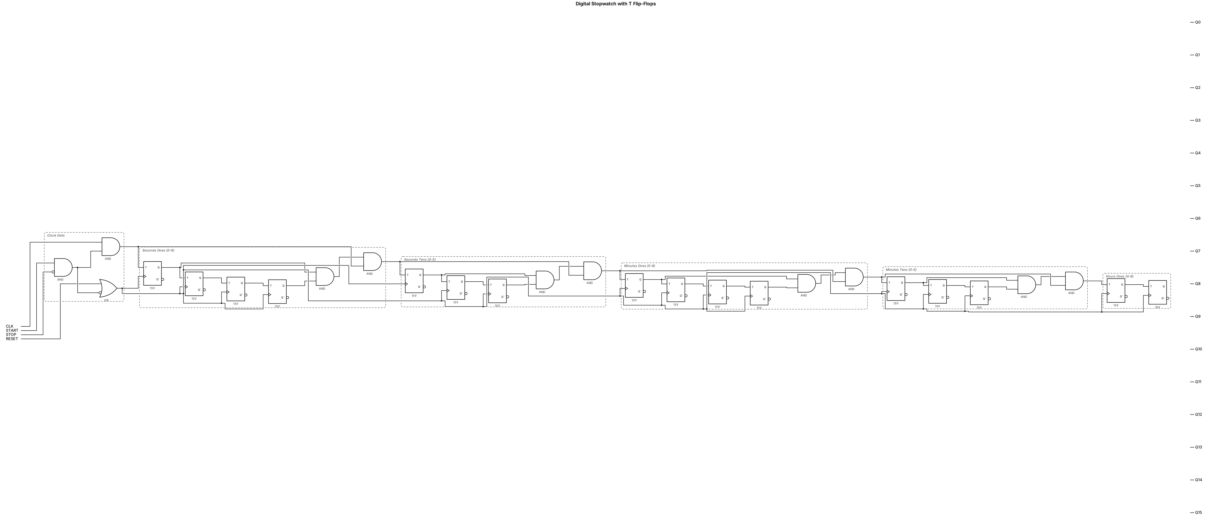
make me degital stopwatch using bild in ciruct make all get in one page use t flipflop
NODE ARCHIVE · REAL DIAGRAM BRIEFS
Diagram Examples from Real Visitor Prompts
Browse eligible diagrams shared by FreeDiagram visitors, inspect the exact prompts, and build your own version.
Browse 3261 real creationsCOMMUNITY OUTPUTS · EXACT PROMPTS
Logic Gate
Showing 145–168 of 288. No stock examples or system defaults. Choose a tool, study a real result, then reopen its prompt as your starting point.
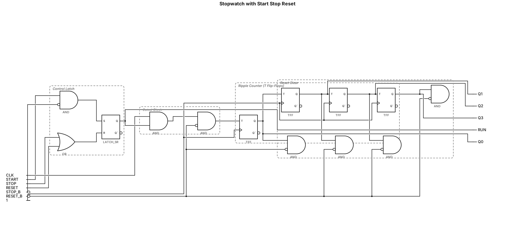
i want to make stop watch and it hsa stat butten , stop butten and rest butten and in this circut use clok puls and t flip flop and what you need and gove me diagram which i can impliment in logisim
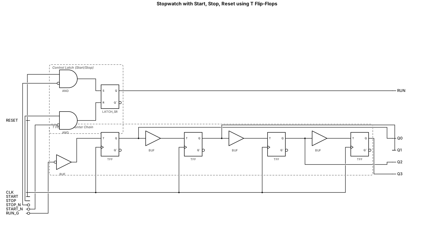
i want to make stop watch and it hsa stat butten , stop butten and rest butten and in this circut use clok puls and t flip flop and what you need
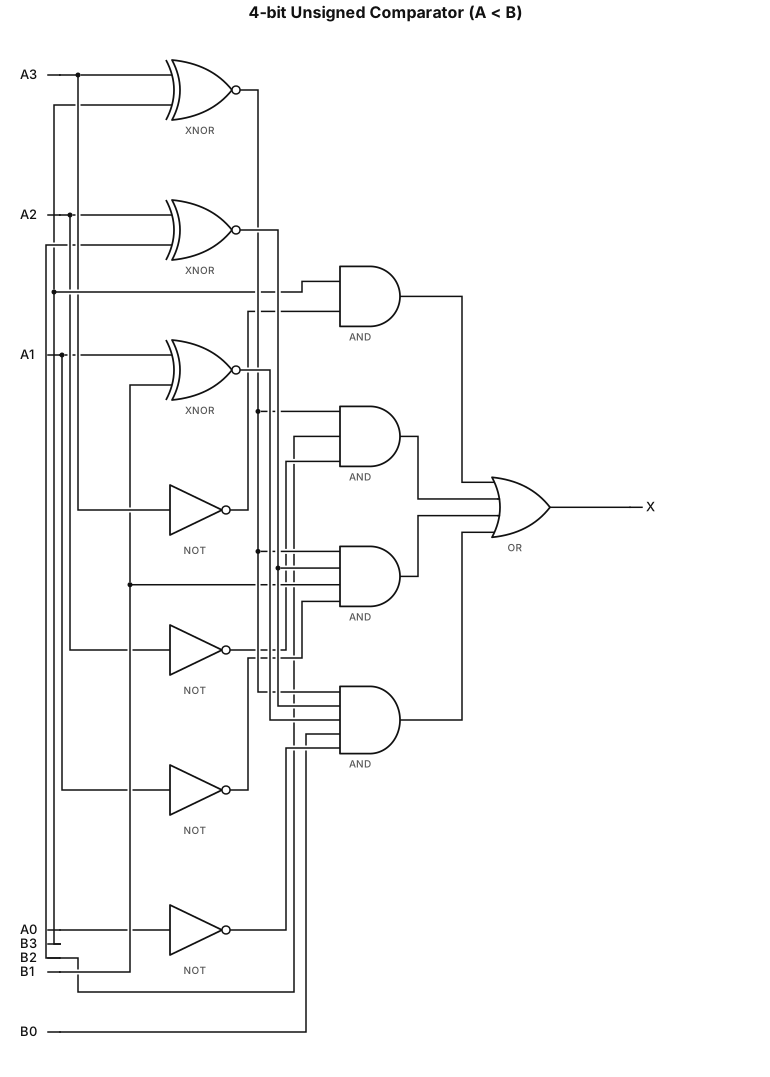
Draw 4-bit unsigned number comparator circuit, IEEE standard gate symbols, textbook style. Input A3 A2 A1 A0, B3 B2 B1 B0, output X. X = (B3 & !A3) | ((A3==B3)&B2&!A2) | ((A3==B3)&(A2==B2)&B1&!A1) | ((A3==B3)&(A2==B2)&(A1==B1)&B0&!A0) Use XOR gate to judge equal, NOT gate for inversion, AND gates, final OR gate for X.
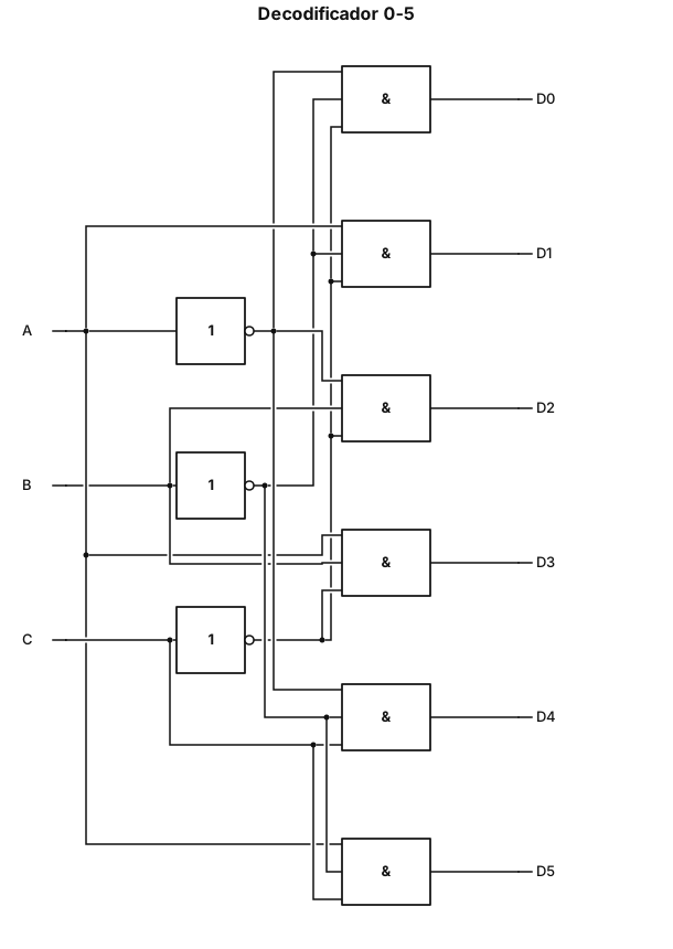
Generame un decodificador del 0 al 5 con compuertas lógicas
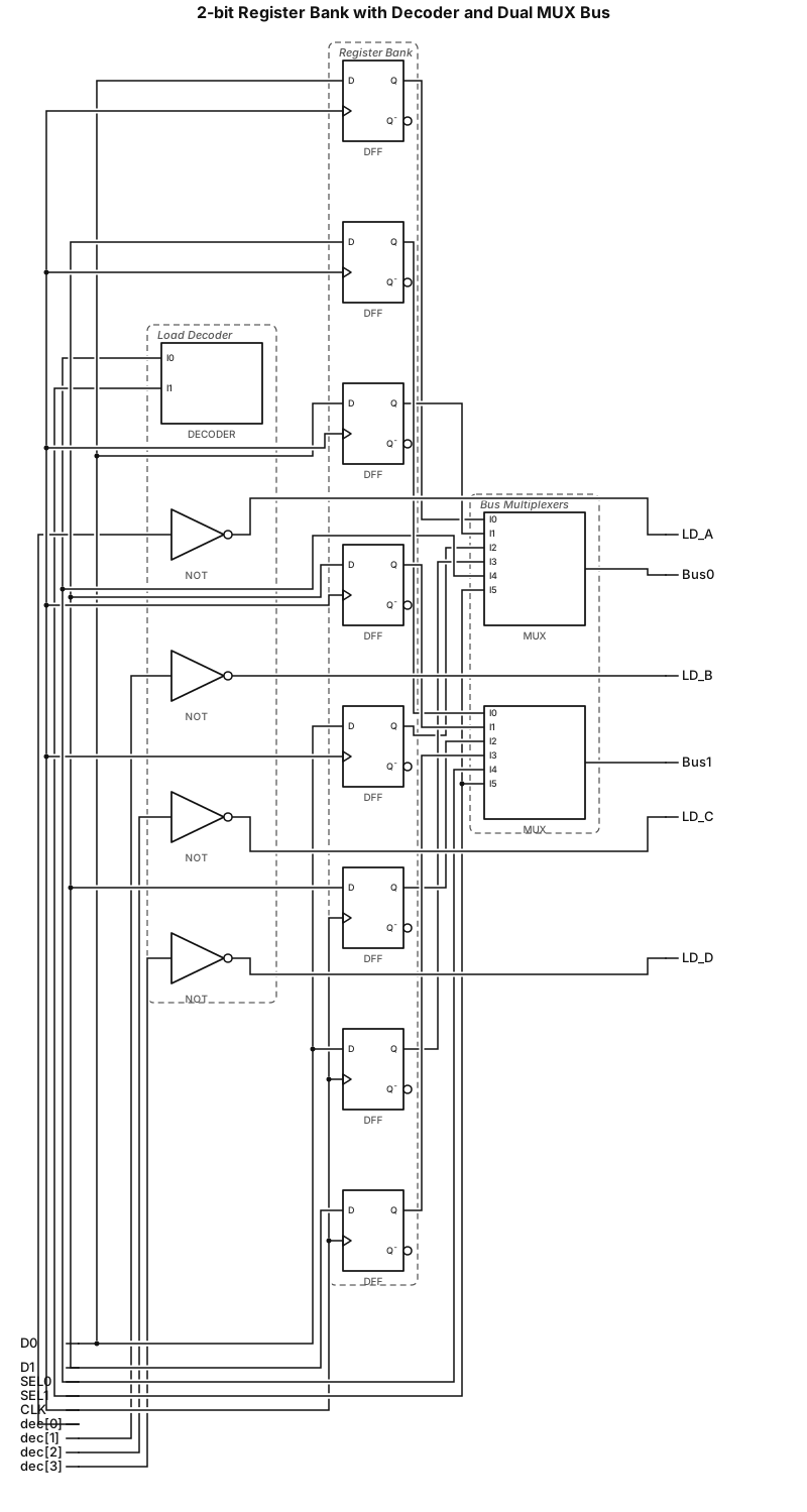
Generate a digital logic block diagram showing a 2-bit register bank (Registers A, B, C, D) connected to a 2x4 decoder for load selection and dual 4-to-1 multiplexers forming a 2-line bus.
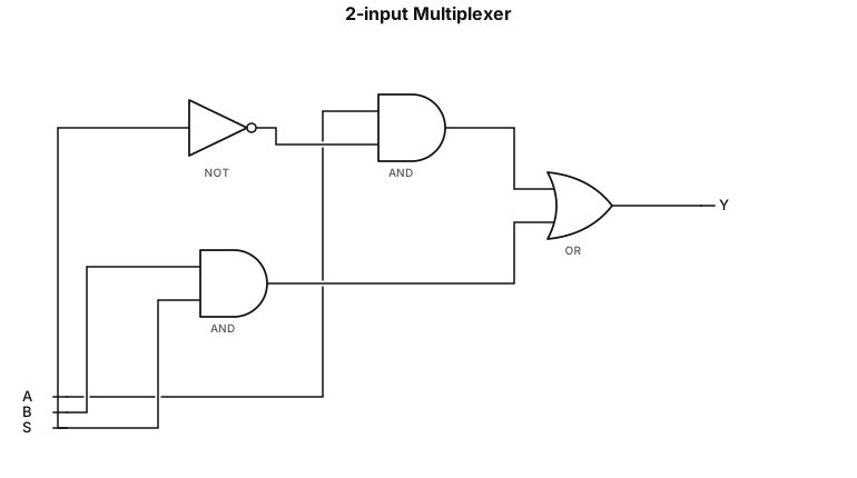
A 2-input multiplexer built from AND, OR, and NOT gates
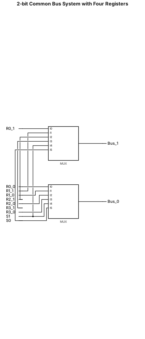
Draw a digital logic circuit for a common bus system connecting four 2-bit registers R0, R1, R2, and R3 using multiplexers only. Use exactly two 4-to-1 multiplexers. Connect the corresponding bit from each register to each multiplexer. Use shared selection lines S1 and S0. Label the two outputs Bus[1] and Bus[0]. Show a clean, academic-style circuit diagram with all wires and labels. Do not replace the multiplexers with logic gates. The circuit must select one complete 2-bit register at a time.
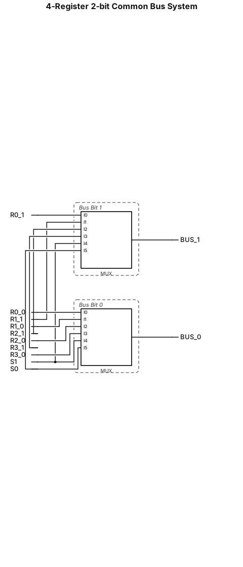
• Construct a common bus system for connecting four registers of 2-bit each. – Using multiplexers
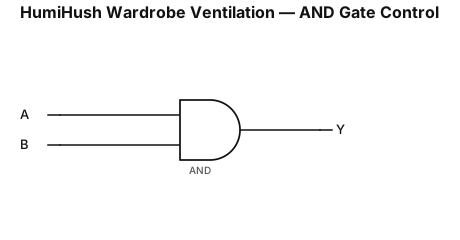
Create a clear and accurate logic gate schematic for the HumiHush wardrobe ventilation system using a two-input AND gate. Label the inputs as A (Humidity Sensor) and B (Enable Switch), and the output as Y = A · B. Show the correct AND gate symbol with both input lines connected to it and one output line labeled Y (Ventilation Fan). Include the truth table (00→0, 01→0, 10→0, 11→1). Use standard digital logic symbols, black lines, clear labels, and a plain white background suitable for a college engineering proposal.
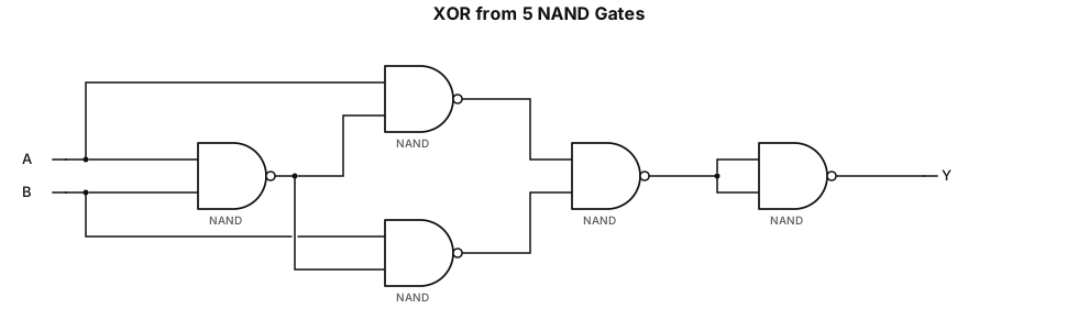
NOT(NOT(A times NOT B) times NOT(NOT A times B)) drawn using 5 2-input NAND gates
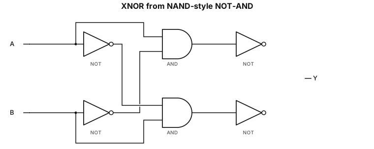
NOT(NOT(A times NOT B) times NOT(NOT A times B))
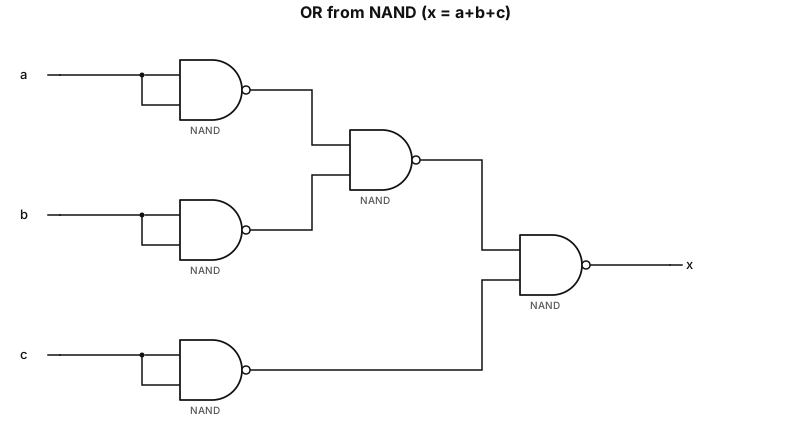
Draw a logic diagram showing how to get the OR function x = a+b+c using 7410 NAND gate assuming all functions and complements are available
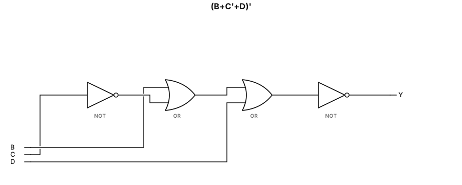
(B+C'+D)'
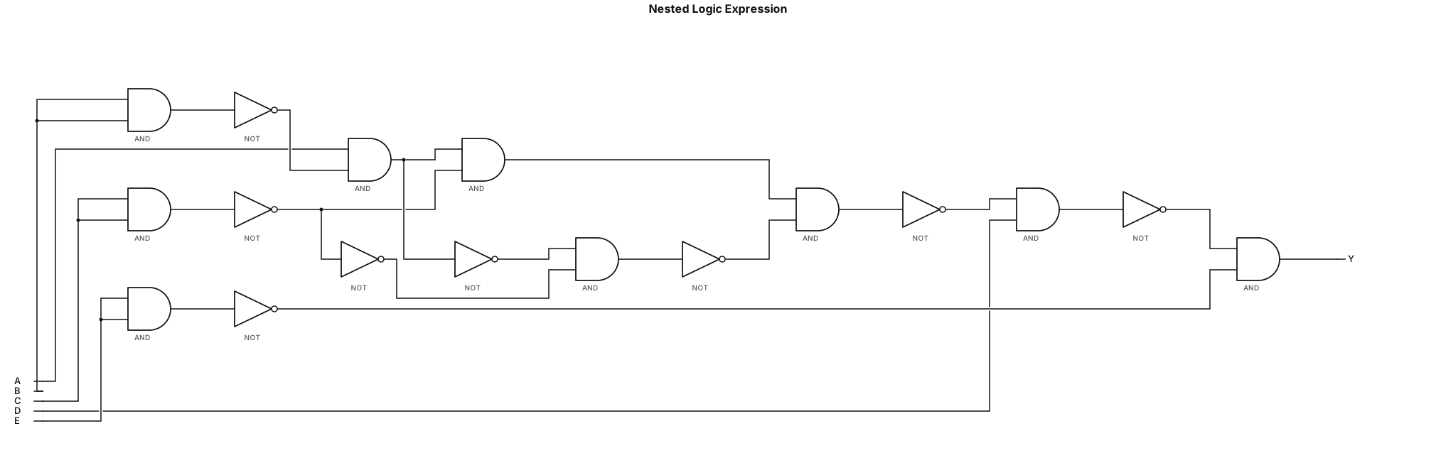
!(!(!(!(!(A && !(B && B)) && !(C && C)) && !(!(A && !(B && B)) && !(C && C))) && D) && !(E && E)) can you change the pattern to where inputs are at the top
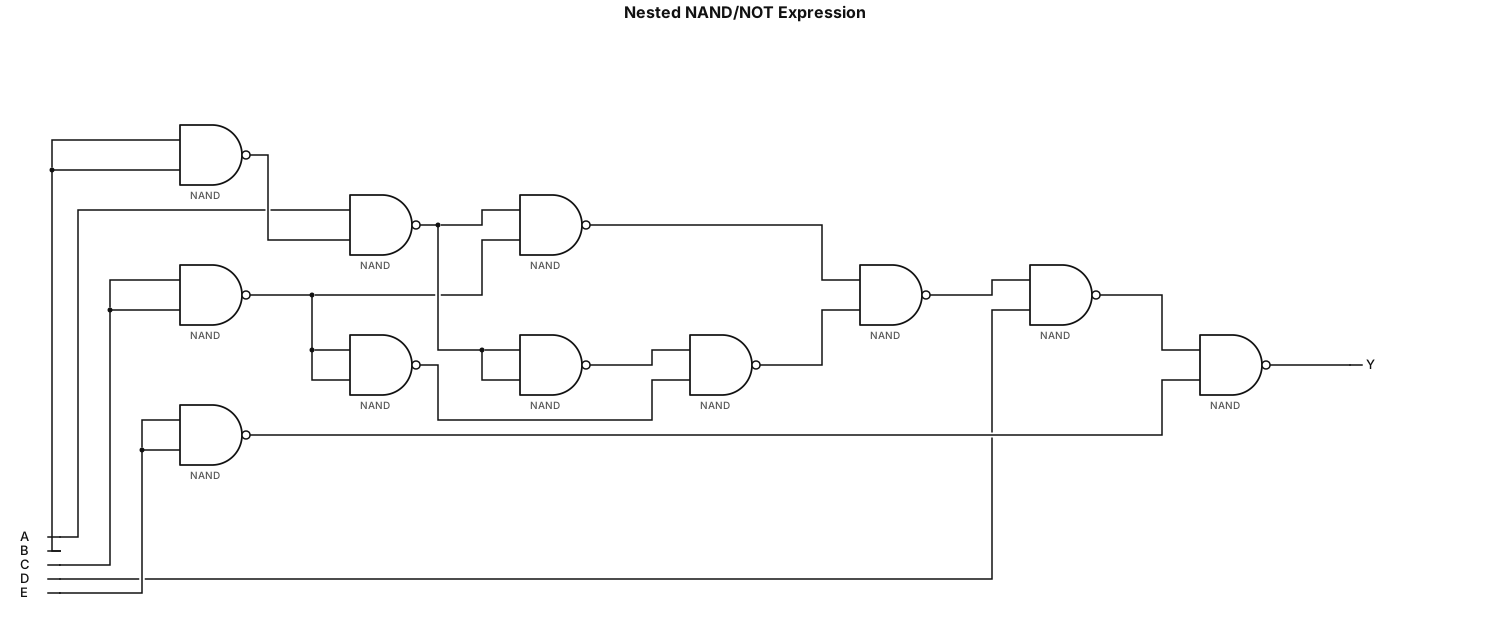
!(!(!(!(!(A && !(B && B)) && !(C && C)) && !(!(A && !(B && B)) && !(C && C))) && D) && !(E && E))
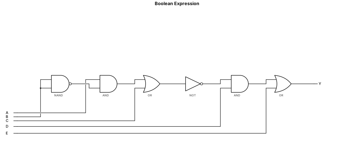
(A * (B NAND B) + C)' * D + E
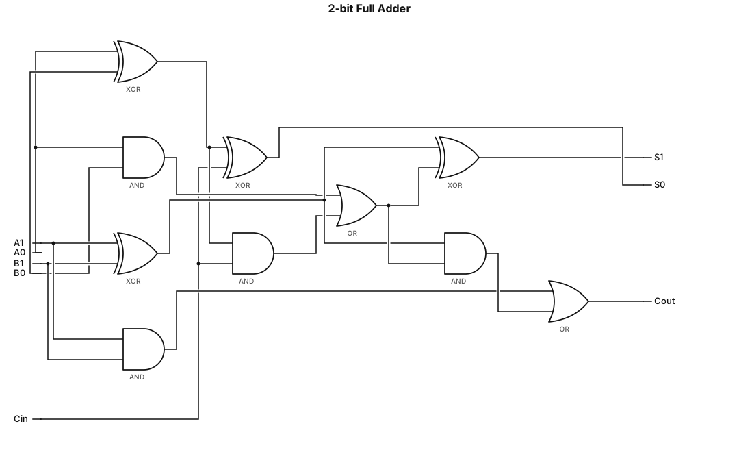
A logic gate circuit for a 2-bit full adder using AND, OR, and XOR gates with inputs A, B, and carry-in, and outputs sum and carry-out
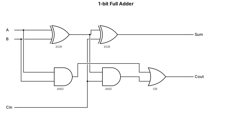
A 1-bit full adder logic circuit using AND, OR, and XOR gates with carry-in and carry-out
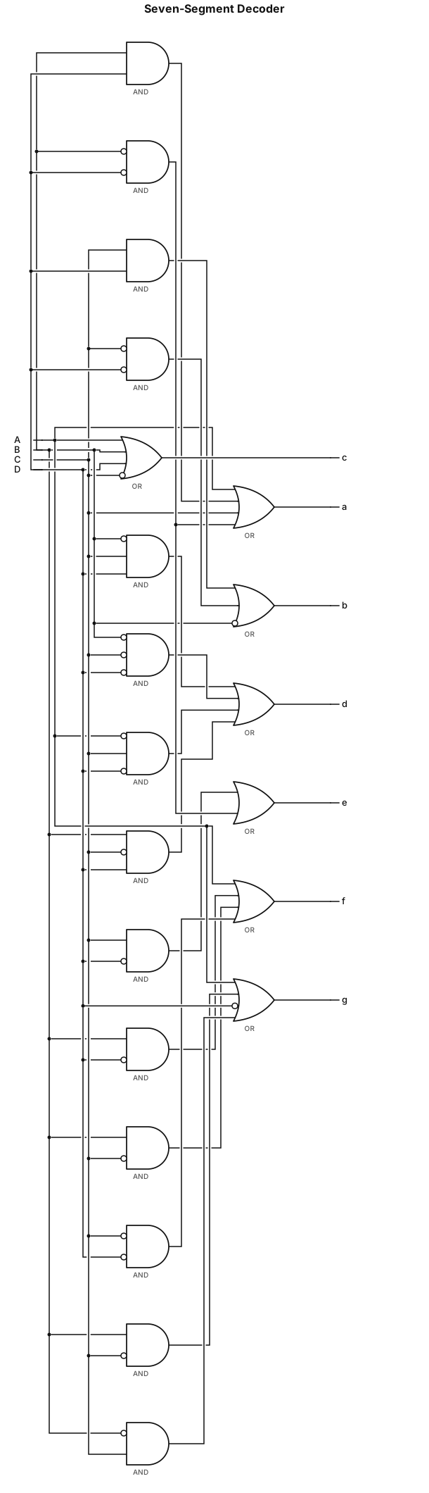
a = A + B D + C + B' D'; b = C D + C' D' + B' ; c = A + B + D + C' ; d = B' C D + B' C' D' + A' C D' + B C' D; e = C D' + B' D'; f = A + B D' + B C' + C' D'; g = A + B C' + D' + B' C ;
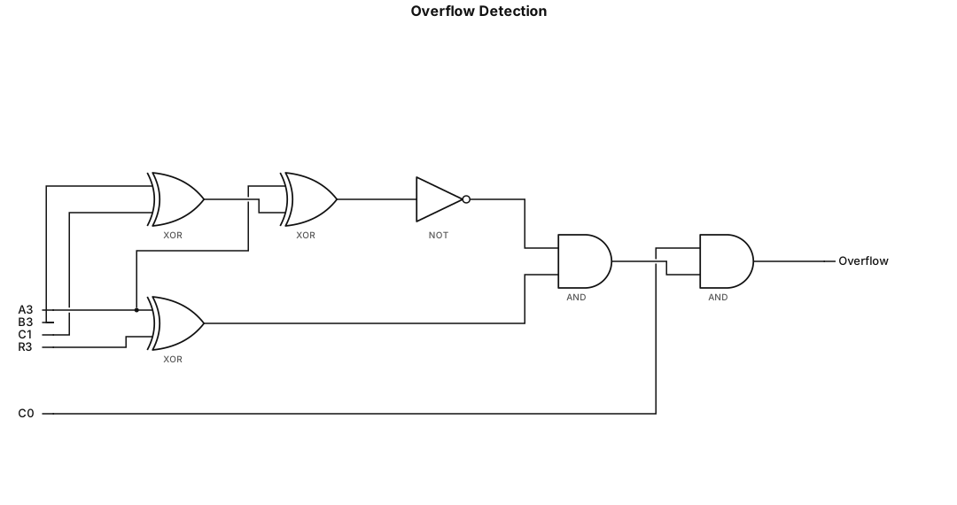
Overflow equals $C_0$ AND the logical AND of two parts: first, the NOT of (A_3 XOR (B_3 XOR C_1)), and second, (A_3 XOR R_3).
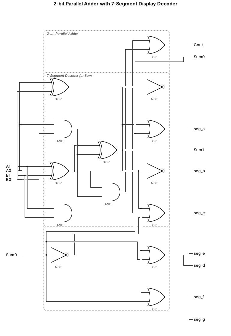
Create a seven-segment display decoder for the display of the SUM and CARRY of 2 – bit Parallel Adder. It is alright if the 7 segment display is only a simplified combinational circuit
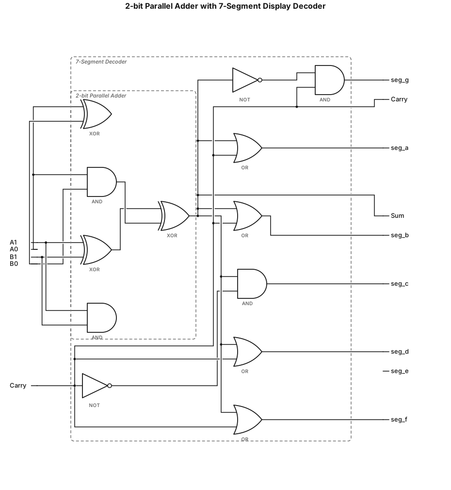
Create a seven-segment display decoder for the display of the SUM and CARRY of 2 – bit Parallel Adder.
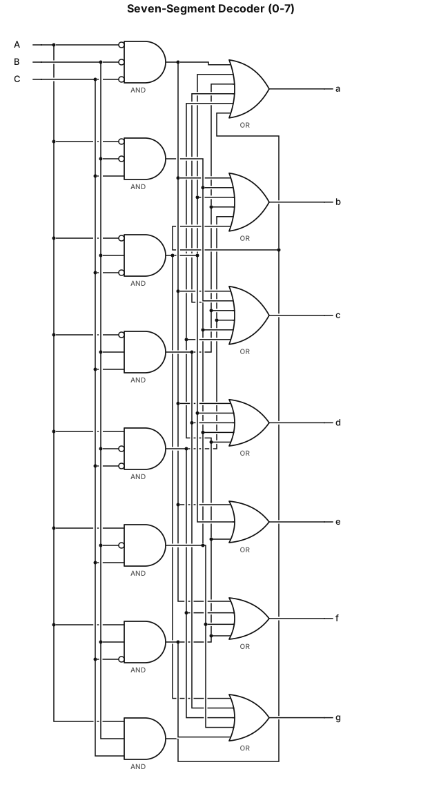
Draw the circuit diagram of Seven – Segment Decoder ( 0 - 7 ), if possible the actual inside! using the logic gates