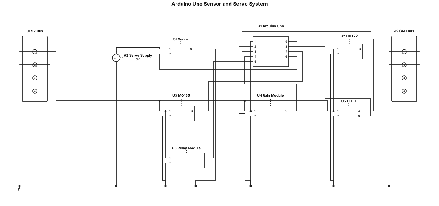
Arduino and sensors Power the Uno from USB. Use separate 5V and GND terminal buses for the low-voltage modules: Component pin Connect to Uno 5V 5V bus Uno GND GND bus DHT22 VCC, GND, DATA 5V bus, GND bus, Uno D2 MQ135 VCC, GND, AO 5V bus, GND bus, Uno A0 Rain module VCC, GND, DO 5V bus, GND bus, Uno D3 OLED VCC, GND, SDA, SCL 5V bus, GND bus, Uno A4, Uno A5 Relay module VCC, GND, IN 5V bus, GND bus, Uno D8 For this Uno setup, the MQ135 analog output can connect to A0 directly if the module is powered at 5V and its output does not exceed 5V. The resistor divider discussed earlier is generally for lower-voltage microcontroller inputs, not needed for a 5V Uno in that case. Servo Servo wire Connect to Red (+) Separate regulated 5V supply + Brown/black (GND) Separate supply − and Uno GND Orange/yellow (signal) Uno D9
Diagram Examples from Real Visitor Prompts
Browse eligible diagrams shared by FreeDiagram visitors, inspect the exact prompts, and build your own version.
Browse 3297 real creationsAll visitor creations
Showing 1681–1704 of 3297. No stock examples or system defaults. Choose a tool, study a real result, then reopen its prompt as your starting point.
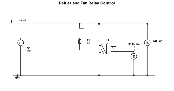
12V supply + -> fuse -> split | +-> relay COM | relay NO -> Peltier + | +-> Fan + 12V supply - ---------------> Peltier - \--------------> Fan -
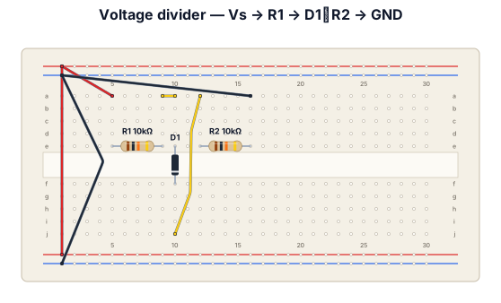
Vs -> R1 -> D1//R2 -> GND R1 = 10kΩ, R2 = 10kΩ 2) Function generator를 이용하여 다음 조건으로 Vs를 인가한다. Sine, 1kHz, VHI = 10V, VLOW = -2V, Phase = 0 3) Oscilloscope를 이용하여 입력에 대한 Vout을 측정한다. 4) 측정한 Data로 Vs - Vout 그래프를 작성한다.
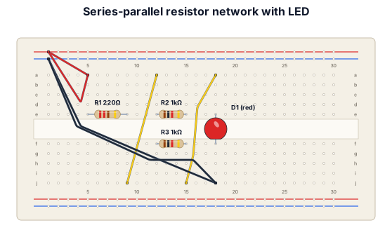
A breadboard in series with a resistor then it converges into parallel with a resistor on each branch, then goes back to a single led
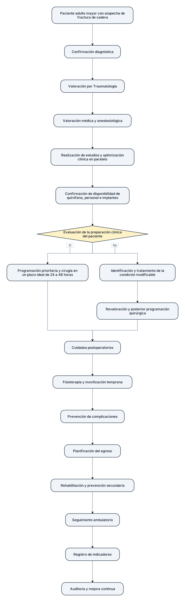
puedes hacer el siguiente flujograma con las flechas mas pequeñas, de manera que quepa en una hoja tamaño cara: Paciente adulto mayor con sospecha de fractura de cadera. Confirmación diagnóstica. Valoración por Traumatología. Valoración médica y anestesiológica. Realización de estudios y optimización clínica en paralelo. Confirmación de disponibilidad de quirófano, personal e implantes. Evaluación de la preparación clínica del paciente: Sí: programación prioritaria y cirugía en un plazo ideal de 24 a 48 horas. No: identificación y tratamiento de la condición modificable, revaloración y posterior programación quirúrgica. Cuidados postoperatorios. Fisioterapia y movilización temprana. Prevención de complicaciones. Planificación del egreso. Rehabilitación y prevención secundaria. Seguimiento ambulatorio. Registro de indicadores. Auditoría y mejora continua. La cirugía dentro de las primeras 24–48 horas debe realizarse siempre que el estado clínico del paciente lo permita y de acuerdo con la valoración del equipo tratante.
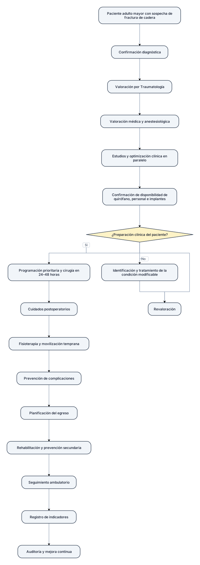
Secuencia resumida Paciente adulto mayor con sospecha de fractura de cadera. Confirmación diagnóstica. Valoración por Traumatología. Valoración médica y anestesiológica. Realización de estudios y optimización clínica en paralelo. Confirmación de disponibilidad de quirófano, personal e implantes. Evaluación de la preparación clínica del paciente: Sí: programación prioritaria y cirugía en un plazo ideal de 24 a 48 horas. No: identificación y tratamiento de la condición modificable, revaloración y posterior programación quirúrgica. Cuidados postoperatorios. Fisioterapia y movilización temprana. Prevención de complicaciones. Planificación del egreso. Rehabilitación y prevención secundaria. Seguimiento ambulatorio. Registro de indicadores. Auditoría y mejora continua. La cirugía dentro de las primeras 24–48 horas debe realizarse siempre que el estado clínico del paciente lo permita y de acuerdo con la valoración del equipo tratante.
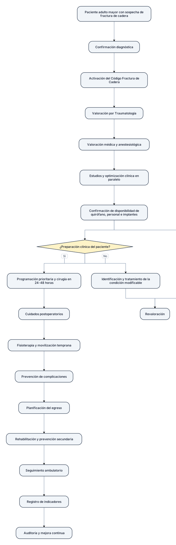
Secuencia resumida Paciente adulto mayor con sospecha de fractura de cadera. Confirmación diagnóstica. Activación del Código Fractura de Cadera. Valoración por Traumatología. Valoración médica y anestesiológica. Realización de estudios y optimización clínica en paralelo. Confirmación de disponibilidad de quirófano, personal e implantes. Evaluación de la preparación clínica del paciente: Sí: programación prioritaria y cirugía en un plazo ideal de 24 a 48 horas. No: identificación y tratamiento de la condición modificable, revaloración y posterior programación quirúrgica. Cuidados postoperatorios. Fisioterapia y movilización temprana. Prevención de complicaciones. Planificación del egreso. Rehabilitación y prevención secundaria. Seguimiento ambulatorio. Registro de indicadores. Auditoría y mejora continua. La cirugía dentro de las primeras 24–48 horas debe realizarse siempre que el estado clínico del paciente lo permita y de acuerdo con la valoración del equipo tratante.
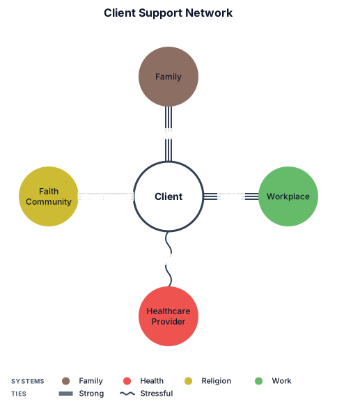
An ecomap of a client's support network: family, work, healthcare, and faith community, with strong and stressful ties
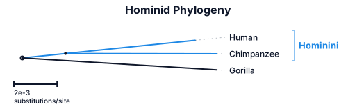
A phylogenetic tree of humans, chimpanzees, and gorillas
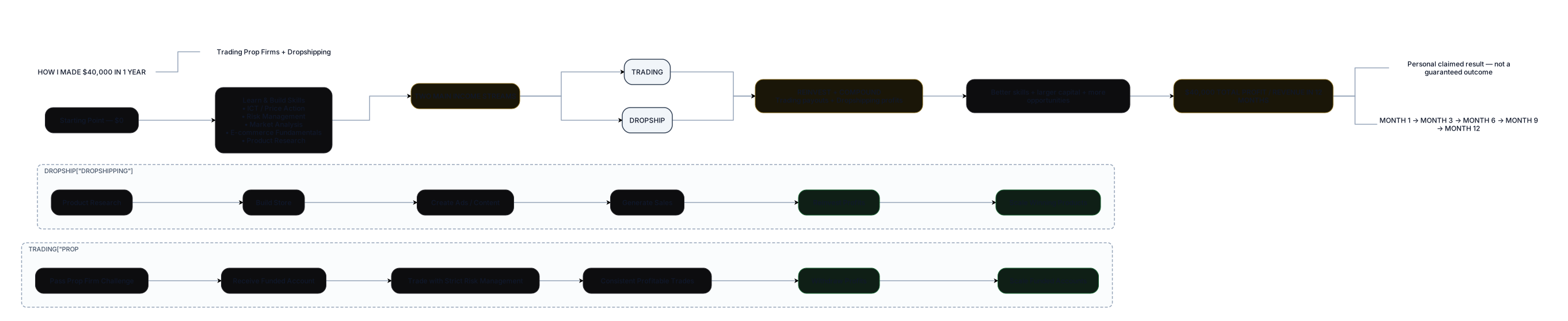
Create a professional, cinematic infographic diagram titled: “HOW I MADE $40,000 IN 1 YEAR” Subtitle: “Trading Prop Firms + Dropshipping” Create a clear left-to-right roadmap showing the journey over 12 months. START: “Starting Point — $0” ↓ “Learn & Build Skills” • ICT / Price Action • Risk Management • Market Analysis • E-commerce Fundamentals • Product Research ↓ SPLIT INTO TWO MAIN INCOME STREAMS: 1. PROP FIRM TRADING “Funded Account” → Pass Prop Firm Challenge → Receive Funded Account → Trade with Strict Risk Management → Consistent Profitable Trades → Withdraw Profits → Scale Funded Accounts Show this as a growing path: $0 → Challenge → Funded Account → Payouts → Scaling 2. DROPSHIPPING “E-Commerce Store” → Product Research → Build Store → Create Ads / Content → Generate Sales → Reinvest Profits → Scale Winning Products Show this as a growing path: $0 → First Sale → Profitable Product → Reinvestment → Scaling MERGE BOTH STREAMS: “REINVEST + COMPOUND” Trading payouts + Dropshipping profits ↓ Better skills + larger capital + more opportunities ↓ “$40,000 TOTAL PROFIT / REVENUE IN 12 MONTHS” Add a timeline underneath: MONTH 1 → MONTH 3 → MONTH 6 → MONTH 9 → MONTH 12 Visual style: • Premium financial/business infographic • Dark black background • White typography • Subtle green accents for growth/profit • Gold accents for important milestones • Clean arrows connecting every stage • Modern glassmorphism cards • Minimal but detailed • Professional hedge-fund / startup aesthetic • 16:9 landscape • High resolution • Easy to understand at a glance • No unnecessary decorative elements Important: Do NOT imply guaranteed results or that this method works for everyone. Present the $40,000 as a personal hypothetical/claimed result over one year, not as a guaranteed outcome.
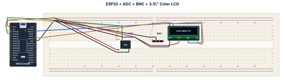
Create a wiring diagram for a esp32 a digital to analog adc and a bnc module with a 3.5 color lcd screen
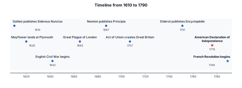
Timeline from 1610 to 1790
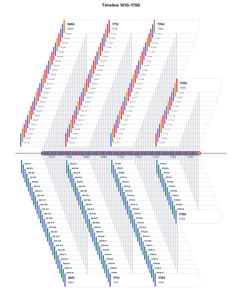
Timeline from 1610 to 1790 with marks for every year.
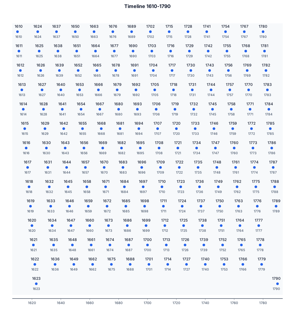
Timeline from 1610 to 1790 with dates for every year.
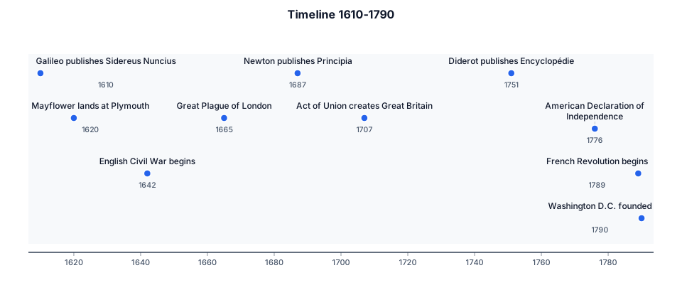
Timeline from 1610 to 1790.
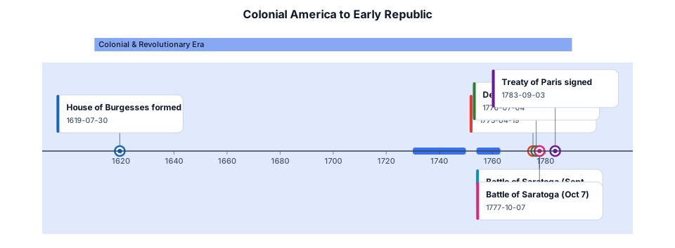
Timeline from 1610 to 1790. House of Burgess's formed on July 30, 1619. Great Awakening in 1730-1750. French and Indian War from 1754-1763. Battle of Lexington and Concord on April 19, 1775. Declaration of Independence signed on July 4, 1776. Battles of Saratoga on September 19 and October 7, 1777. Battle of Yorktown on September 28, 1781-October 19, 1781. Treaty of Paris signed on September 3, 1783.
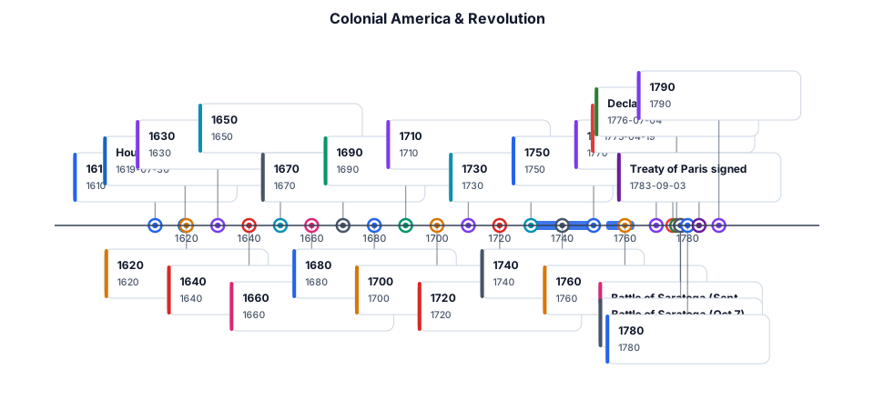
Timeline from 1610 to 1790 with a mark for every 10 years. House of Burgess's formed on July 30, 1619. Great Awakening in 1730-1750. French and Indian War from 1754-1763. Battle of Lexington and Concord on April 19, 1775. Declaration of Independence signed on July 4, 1776. Battles of Saratoga on September 19 and October 7, 1777. Battle of Yorktown on September 28, 1781-October 19, 1781. Treaty of Paris signed on September 3, 1783.
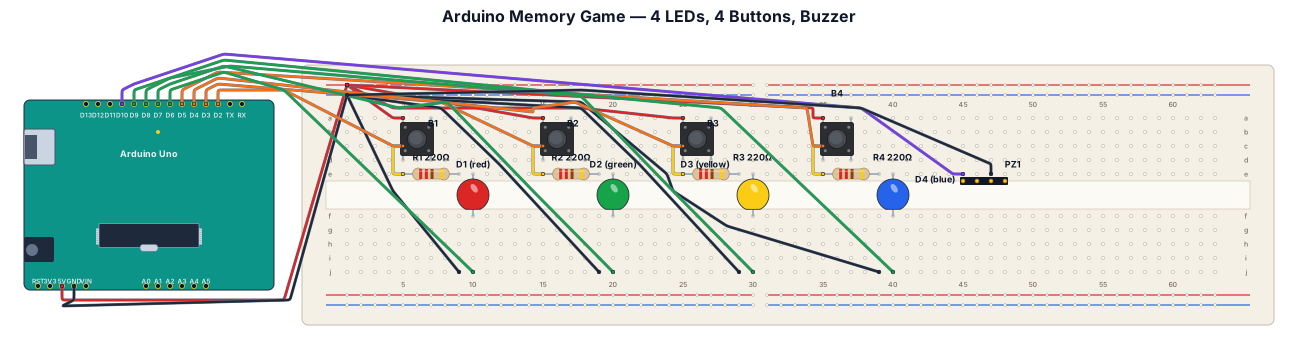
Create a 2D breadboard wiring diagram for an Arduino Memory Game. Use: * 1 Arduino Uno * 1 breadboard * 4 LEDs * 4 push buttons * 4 resistors (220 ohms) * 1 buzzer * Jumper wires Connect the 4 LEDs and 4 buttons to the Arduino so that each button controls one LED. The buzzer should be connected to the Arduino. The game should work as a memory game: the Arduino shows a sequence using the LEDs, and the player repeats the sequence using the buttons. Show all components, pins, and wire connections clearly in a simple top-down 2D breadboard layout.
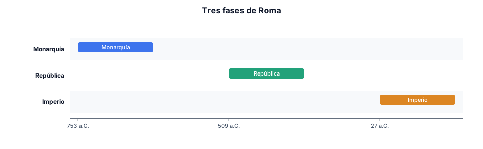
Tres faces de Roma, anarquía, republica y imperio crea una linea de tiempo no tan larga
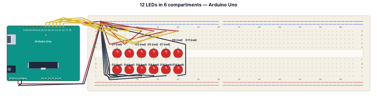
An Arduino breadboard with 12 LEDs connected to it, which are in turn connected to the main Arduino board. These LEDs are arranged in a column, with 2 LEDs in each compartment, and the distance between the compartments is 2.
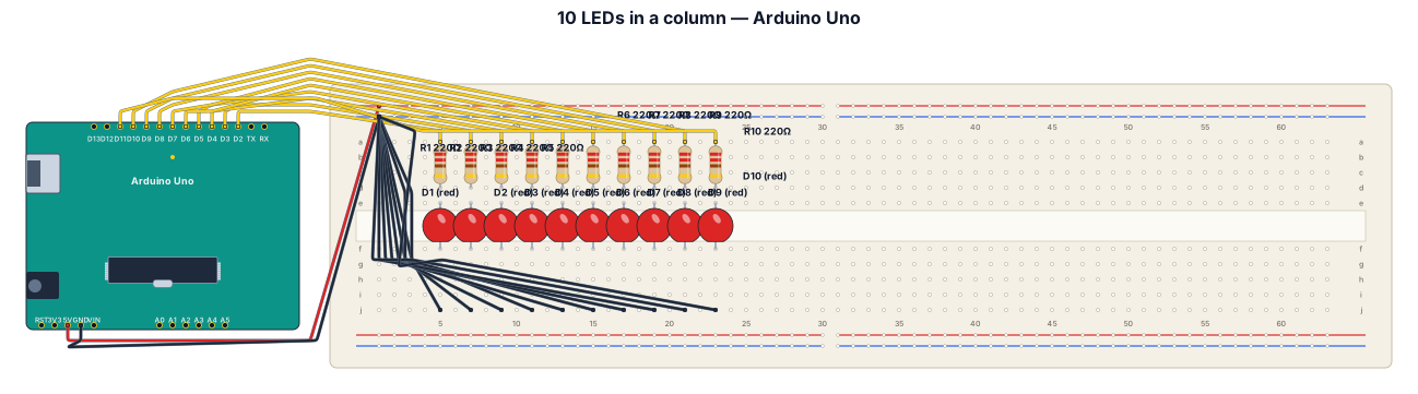
An Arduino breadboard with 10 LEDs connected to it, which are connected to the main Arduino board. These LEDs are arranged in a column.
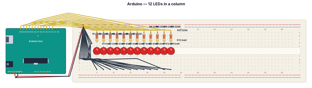
An Arduino breadboard with 12 LEDs connected to it, which are connected to the main Arduino board. These LEDs are arranged in a column.
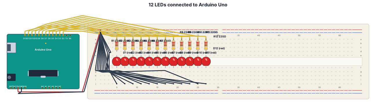
An Arduino breadboard with 12 LEDs connected to it, which are in turn connected to the main Arduino board.
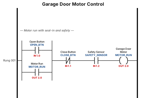
Title: Garage Door Motor Control (Digital I/O Practice) Scenario: You are asked to design a control system for a garage door motor. The system should behave as follows: The motor runs when the Open Button is pressed. The motor stops when the Close Button is pressed. The motor will only run if the Safety Sensor is clear (not blocked). Inputs: Open Button (momentary pushbutton) Close Button (momentary pushbutton) Safety Sensor (closed = clear, open = blocked) Outputs: Garage Door Motor Your Task: Draw the ladder logic diagram for this system using contacts and coils. Include the Open Button, Close Button, and Safety Sensor as inputs. Include the Garage Door Motor as the output. Make sure the motor stays on after the Open Button is pressed. Label all inputs and outputs clearly.