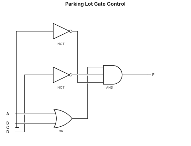
I want to design a digital logic circuit for a parking lot system. The system has four input switches: * A = Car detected at Entrance 1 * B = Car detected at Entrance 2 * C = Parking lot full * D = Emergency mode The output is: * F = Gate Open The logic should work as follows: The gate should open when a car is detected at either entrance (A OR B), as long as the parking lot is not full (NOT C) and the system is not in emergency mode (NOT D). Boolean expression: F = (A + B) · C’ · D’ Please create the complete logic gate diagram using only AND, OR, and NOT gates. I also need a detailed explanation of every connection. Clearly identify: 1. Each input. 2. Each AND, OR, and NOT gate. 3. Which input goes to which gate input. 4. Which gate output connects to which gate input. 5. The final output F. Explain the connections step by step so I can build the same circuit physically or in a digital logic simulator.
Diagram Examples from Real Visitor Prompts
Browse eligible diagrams shared by FreeDiagram visitors, inspect the exact prompts, and build your own version.
Browse 3263 real creationsLogic Gate
Showing 193–216 of 288. No stock examples or system defaults. Choose a tool, study a real result, then reopen its prompt as your starting point.
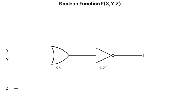
F(X,Y,Z)=(X+Y)’
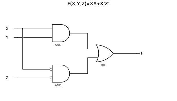
F(X,Y,Z)=XY+X’Z’
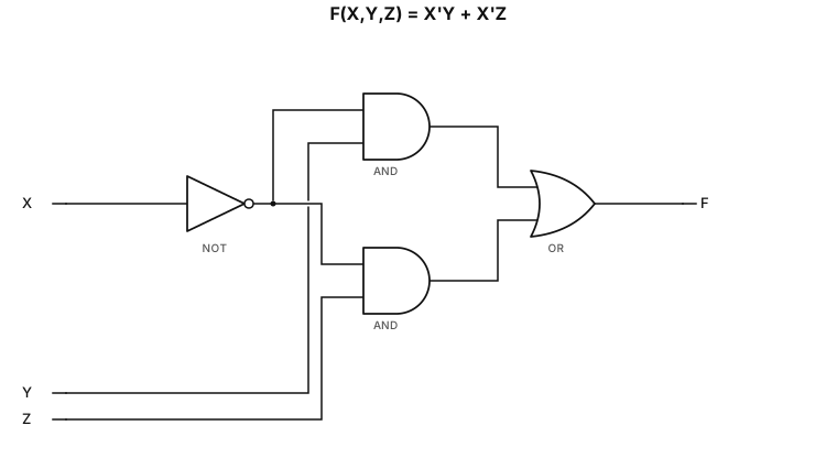
F(X,Y,Z)=X’Y+X’Z
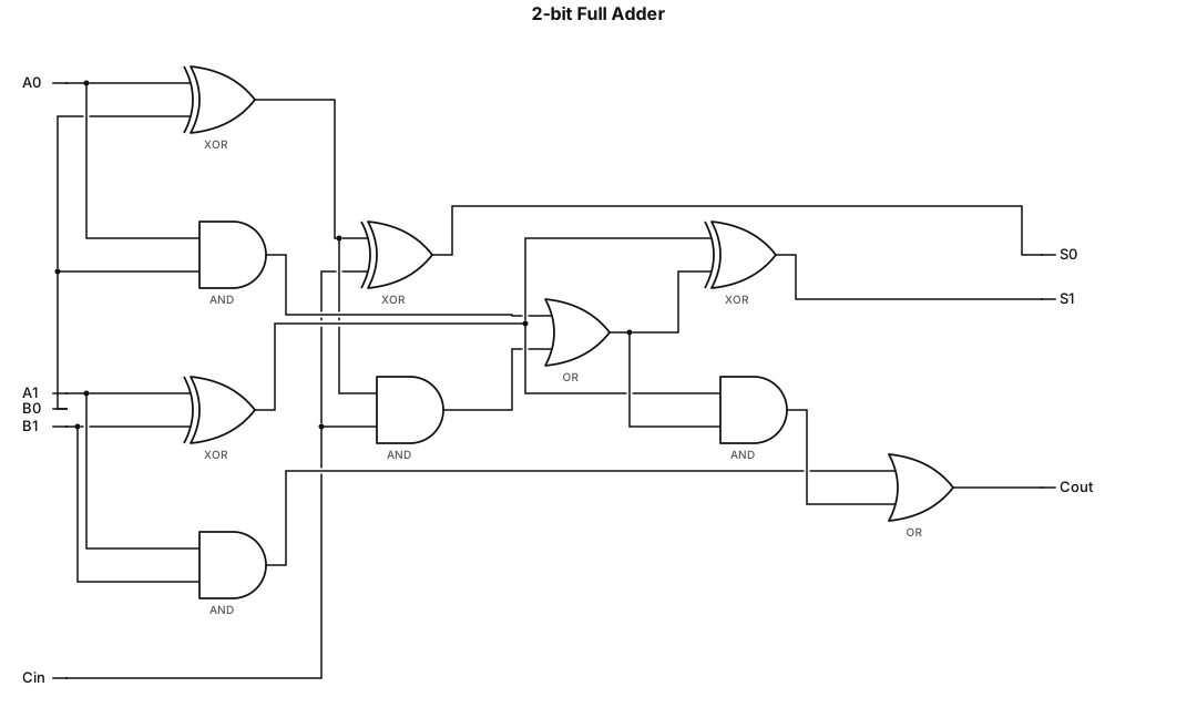
A logic gate circuit for a 2-bit full adder using AND, OR, and XOR gates with inputs A, B, and carry-in, and outputs sum and carry-out
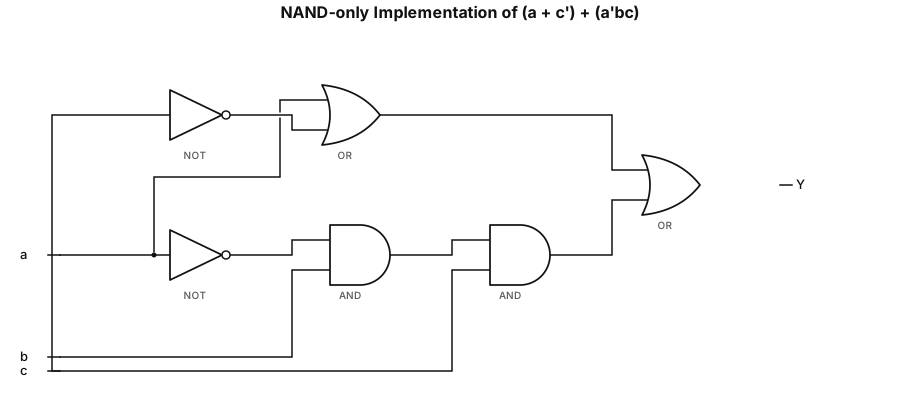
NAND-only implementation of the expression (a + c’) + (a’bc)
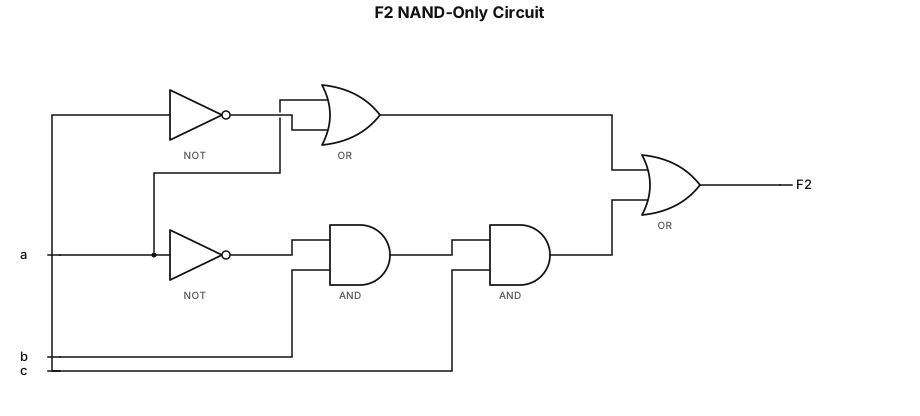
Convert the function F2(a, b, c) = (a + c’) + (a’bc) to a function with only two-input NAND gates using Demorgan’s and Involution laws. Draw the gate level circuit of the converted function
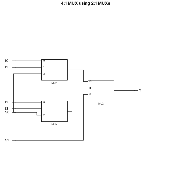
Design a 4:1 multiplexer using 2:1 multiplexers
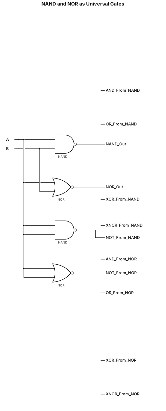
TO STUDY AND VERIFY OF NAND AND NOR GATES AS A UNIVERSAL GATES make all the logic gates
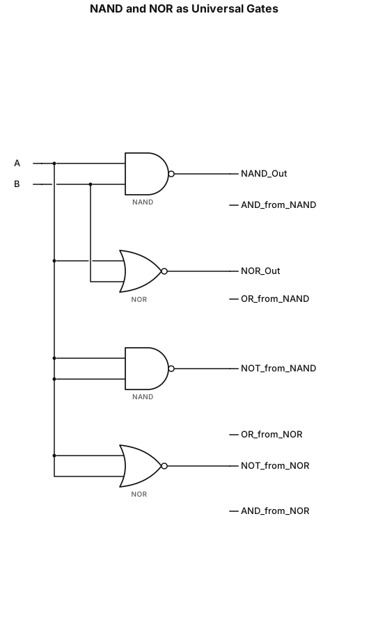
TO STUDY AND VERIFY OF NAND AND NOR GATES AS A UNIVERSAL GATES
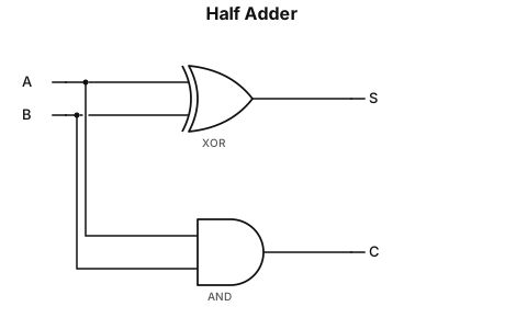
Create a clean digital logic circuit for a Half Adder. Inputs: A and B Outputs: S and C Use two separate gates: 1. A and B are connected to a 2-input XOR gate. Label the XOR gate output as S. Boolean expression: S = A XOR B 2. A and B are also connected to a 2-input AND gate. Label the AND gate output as C. Boolean expression: C = AB The same inputs A and B must branch and connect to both gates. Arrange the circuit neatly: - XOR gate on the upper path, output S - AND gate on the lower path, output C - Inputs A and B on the left - Outputs S and C on the right Use standard digital logic gate symbols, straight wires, black lines, white background, and a clean textbook-style circuit diagram.
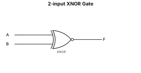
Create a clean digital logic circuit for a 2-input XNOR gate. Inputs: A and B Gate: 2-input XNOR gate Output: F Connect input A and input B directly to the XNOR gate. Connect the XNOR gate output to F. Display the Boolean expression exactly as: F = overline(A XOR B) Use ONE continuous horizontal bar above the entire expression A XOR B. The bar must cover the complete A XOR B expression. Do not put separate bars above A or B. Use a standard XNOR gate symbol, black lines, white background, straight horizontal input and output wires, and a clean textbook-style circuit diagram.
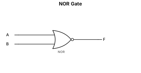
Create a clean digital logic circuit for a NOR gate. Inputs: A and B Gate: 2-input NOR gate Output: F Connect input A and input B to the NOR gate. Connect the NOR gate output to F. Display the Boolean expression exactly as: F = overline(A + B) Use ONE continuous horizontal bar above the entire expression A+B. The bar must cover both A and B and the plus sign. Do not put separate bars above A or B. Use a standard NOR gate symbol, black lines, white background, and a clean textbook-style circuit diagram.
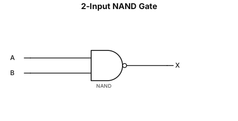
Create a clean digital logic circuit for a NAND gate. Inputs: A and B Gate: 2-input NAND gate Output: X Connect input A and input B to the NAND gate. Connect the NAND gate output to X. Display the Boolean expression as: X = AB with an overbar over the entire AB Use a standard NAND gate symbol, black lines, white background, and a clean textbook-style circuit diagram.
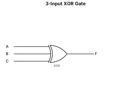
Create a 3-input XOR gate circuit. Inputs: A, B, C Gate: 3-input XOR Output: F Connect A, B, and C directly to the three inputs of the XOR gate. Label the output as F. Use a clean black-and-white digital logic circuit style.
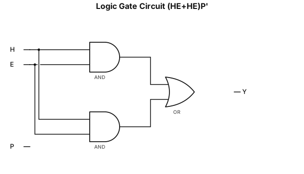
A logic gate circuit of (HE+HE)P'
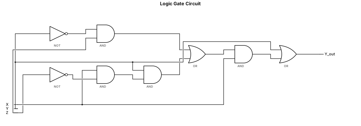
A logic gate circuit for Y + [X! YZ + XY! Z]X
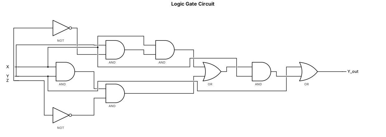
A logic gate circuit for Y+[X!YZ+XY!Z]X
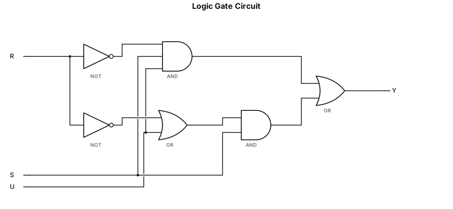
A logic gate circuit for [!(RSU)+(R'+U)]S
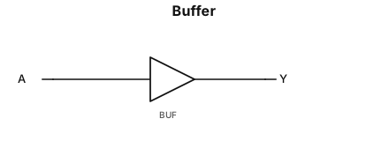
a buffer
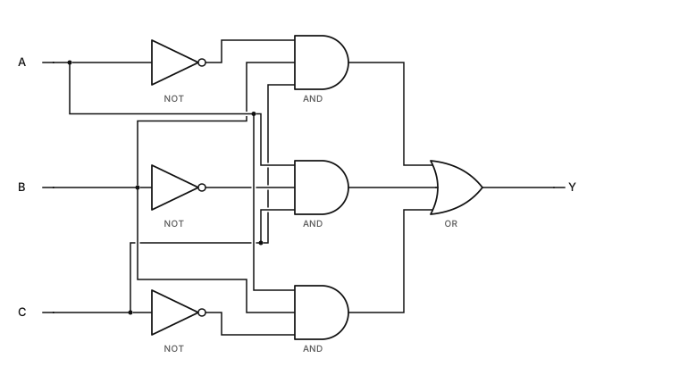
a trinary gate that only takes in inputs that have one 0 inside
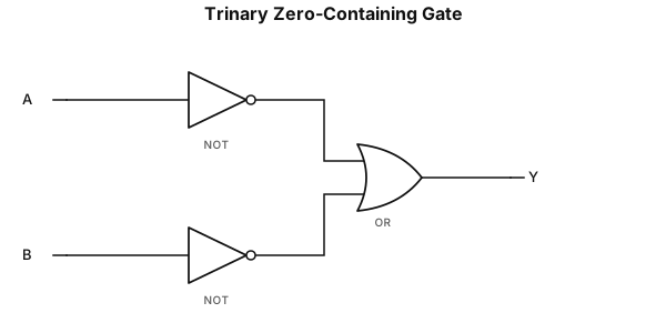
a trinary gate that only takes in inputs that have a 0 inside (01,02,00,10,20)
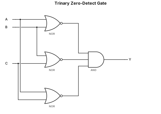
a trinary gate that only takes in inputs that have a 0 inside
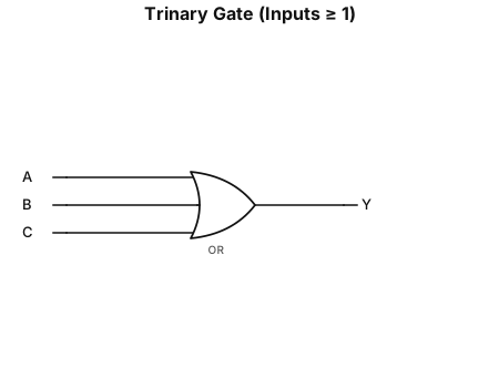
a trinary gate that only takes in inputs bigger than it equal to 1