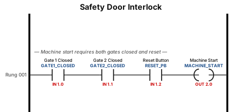
A safety door interlock circuit where a machine cannot start unless two safety gate switches are closed and a reset button is pressed
NODE ARCHIVE · REAL DIAGRAM BRIEFS
Diagram Examples from Real Visitor Prompts
Browse eligible diagrams shared by FreeDiagram visitors, inspect the exact prompts, and build your own version.
Browse 3314 real creationsCOMMUNITY OUTPUTS · EXACT PROMPTS
All visitor creations
Showing 2281–2304 of 3314. No stock examples or system defaults. Choose a tool, study a real result, then reopen its prompt as your starting point.
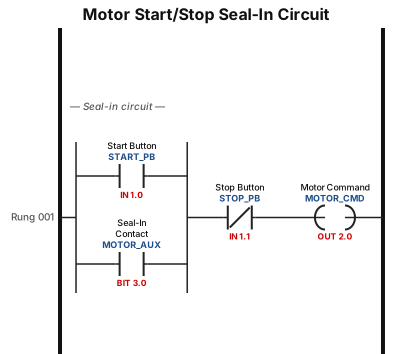
A motor start/stop seal-in circuit with a normally open start button, a normally closed stop button, and a seal-in contact around the start button
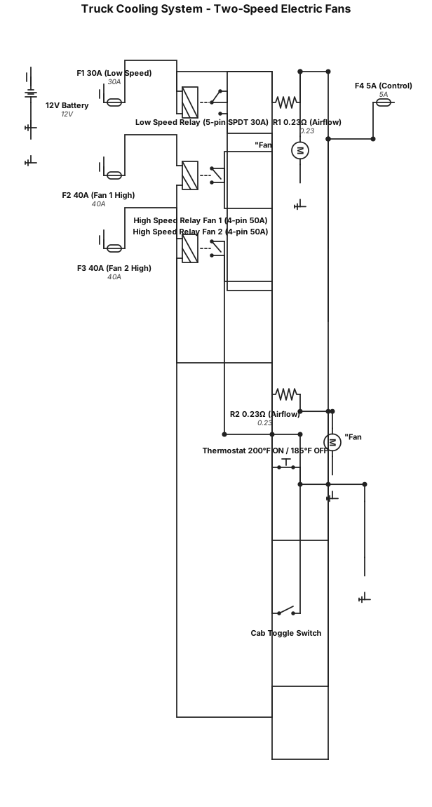
Create an automotive wiring diagram for a truck cooling system with two 12 V, two-wire electric fans that have two speeds: Low Speed: Battery positive → 30 A fuse (close to battery) → Pin 30 of a 5‑pin, 30 A SPDT relay. Pin 87 → 0.23 Ω resistor #1 → Positive terminal of Fan #1. Pin 87a → 0.23 Ω resistor #2 → Positive terminal of Fan #2. Both fan negative terminals go to chassis ground (10–12 AWG). Relay coil: Pin 85 fed from ignition-switched +12 V through a 5 A fuse; Pin 86 connected to a single-wire, normally open thermostat (200 °F ON / 185 °F OFF) that grounds to engine block. High Speed (AND Logic): Fan #1: Battery positive → 40 A fuse (close to battery) → Pin 30 of a 4‑pin, 50 A relay → Pin 87 to Fan #1 positive terminal → Fan #1 negative to chassis ground. Fan #2: Battery positive → 40 A fuse (close to battery) → Pin 30 of a 4‑pin, 50 A relay → Pin 87 to Fan #2 positive terminal → Fan #2 negative to chassis ground. Both high-speed relay coils: Pin 85 fed from ignition-switched +12 V (via same 5 A fuse as low-speed coil feed). Pin 86 connected in series to cab-mounted toggle switch → thermostat output wire → ground. This creates AND logic: high speed only runs when cab switch is ON and thermostat is closed (200 °F+). General Requirements: Show all relays with pin numbers (30, 85, 86, 87, 87a). Show fuse ratings and locations close to battery. Indicate wire gauge placeholders: 10–12 AWG for fan power/ground, 16–18 AWG for control wiring. Show resistors mounted in airflow for cooling. Use standard automotive wiring symbols and clear labels for each component.
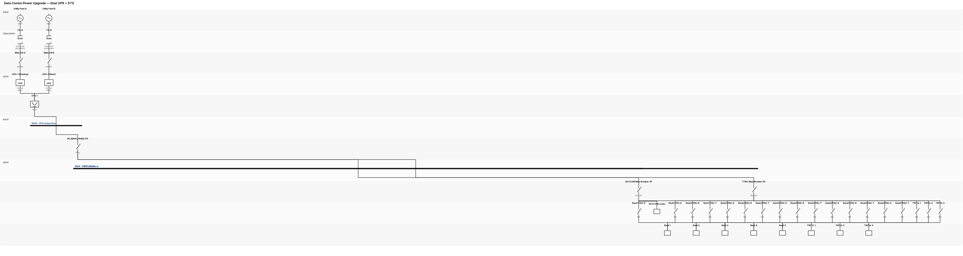
Data center power system with UPS and dual utility feeds. we need diagram for upgrade project, from single ups to dual ups source with STS to output. old line is UPS50KVA to RF_MAIN_PANEL175 then slipt two TTNC_Panel and SATCOM_Panel. from TTNC_Panel distribute to 5 rack with 3 PDU each phase R-S-T, and directly to TWTA1-3 each TWTA using 1 phase. TTNC Panel has 1(one) 3phase Main Breaker input and all output 220V via 16A MiniCircuitBreaker.
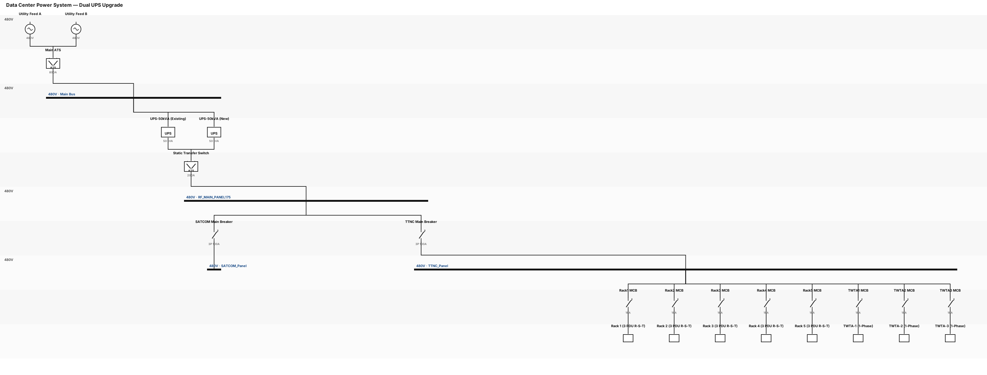
Data center power system with UPS and dual utility feeds. we need diagram for upgrade project, from signle ups to dual ups source with STS to output. old line is UPS50KVA to RF_MAIN_PANEL175 then slipt two TTNC_Panel and SATCOM_Panel. from TTNC_Panel distribute to 5 rack with 3 PDU each phase R-S-T, and directly to TWTA1-3 each TWTA using 1 phase. TTNC Panel has 1(one) 3phase Main Breaker input and all output via 16A MiniCircuitBreaker each line.
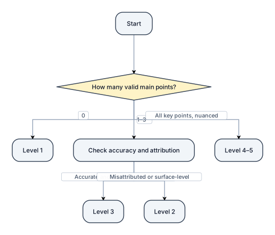
How many valid main points? 0 → Level 1 1–3 → Check accuracy and attribution. If accurate and correctly attributed → Level 3 If misattributed or surface-level → Level 2 All key points, nuanced → Level 4–5
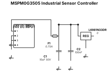
Create a clean professional ELECTRICAL SCHEMATIC, not a PCB layout and not an artistic illustration. The design is a low-cost industrial sensor controller based on TI MSPM0G3505. Use standard electronic schematic symbols. Show component reference designators and values. Use 0603 as the smallest passive package. Never use 0402. Prefer SOIC-8, SOT-23, SOT-223 and LQFP packages. IMPORTANT: Do not invent components. Do not invent connections. Do not add unnecessary components. Do not draw a conceptual block diagram. Draw actual electrical connections with wires and net labels. ================================================== POWER ===== J1 = 24V DC INPUT. 24V_IN → F1 → +24V_PROTECTED. F1 = 0.75A fuse. C1 = 10uF / 50V from +24V_PROTECTED to GND. C2 = 100nF from +24V_PROTECTED to GND. U2 = ST L6981N33DR, SOIC-8. Use U2 as a 24V to 3.3V buck converter. +24V

Create a professional, detailed electrical schematic for a low-cost industrial sensor controller based on the **TI MSPM0G3505SPMR**, 64-pin LQFP. The schematic must be electrically structured and readable, not a decorative illustration. Use standard IEC/ANSI schematic symbols, clear net labels, component reference designators, exact component values, and clearly separated functional blocks. IMPORTANT DESIGN REQUIREMENTS: * Optimize for LOW COST. * All passive SMD components must be **0603 minimum**. Never use 0402 or smaller. * Use SOIC-8, TSSOP, SOT-23, SOT-223 and LQFP packages where possible for easy manual soldering. * Show every passive component around the ICs. * Show exact component values. * Clearly show power rails and where each decoupling capacitor connects. * Clearly distinguish MAIN GROUND from ISOLATED SENSOR GROUND. * Do not electrically connect the isolated sensor ground to the main ground. * Use a clear galvanic isolation barrier. ============================================================ 1. MAIN POWER INPUT ============================================================ Input: J1 = 24 V industrial power input. 24V_IN → F1 → +24V_PROTECTED. F1: * 0.75 A fuse. Add an optional TVS diode footprint: D1 = TVS diode, DNP initially. Clearly mark it "DNP / OPTIONAL". Input capacitors: C1 = 10 µF / 50 V, 1206, X7R C2 = 100 nF / 50 V, 0603 Both connected from +24V_PROTECTED to GND_MAIN. ============================================================ 2. MAIN 24 V → 3.3 V POWER SUPPLY ================================= Use: U2 = **ST L6981N33DR** * Fixed 3.3 V output * Low Noise Mode * SOIC-8 The schematic must show the complete buck converter, including: * VIN connection * SW node * inductor * output capacitors * ground * feedback/fixed-output configuration * all required datasheet support components. Use: L1 = 22 µH shielded power inductor, approximately ≥2 A saturation/current rating. Suggested example: TDK B82464G

An org chart for a 30-person startup with a CEO, CTO, CMO, and VP of Sales at the top — then engineering, product, marketing, and sales teams below with their leads
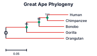
A phylogenetic tree of the great apes: humans, chimpanzees, bonobos, gorillas, and orangutans, with branch lengths and bootstrap support values
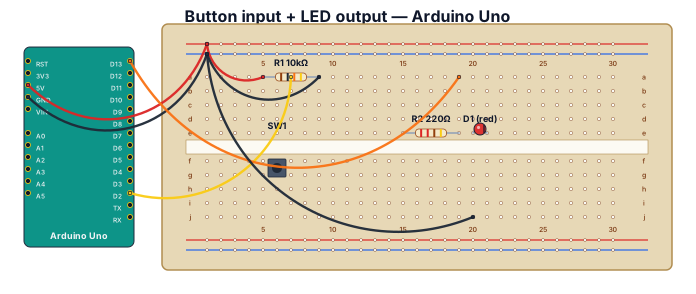
A breadboard wiring diagram for an Arduino Uno reading a button press and lighting an LED: button with pull-down resistor on D2, LED with 220-ohm resistor on D13

A mind map for planning a two-week trip — flights, hotels, activities, and budget Alors il faut que tu me fasses un schéma je suis en P SVT donc terminal donc il faut que tu me fasses un schéma avec quelques petites croquis à côté enfin une petite image à côté de chaque truc étape donc je te dis d'abord il faut que tu mets gravité par la suite il y a la racine placée horizontalement qui arrive ensuite il y a le déplacement des amis le places vers la partie inférieure qui arrive ensuite on a une perception de la gravité on a une modification de répartition des hormones ensuite ensuite il y a une modification de l'élongation entre les deux côtés de la racine ensuite on a une courbure ensuite la racine orientée vers le bas ensuite le gravitopisme et positive
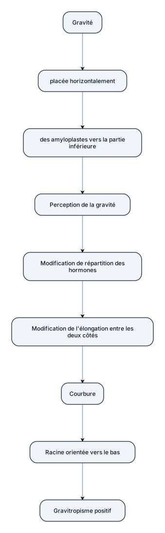
Alors il faut que tu me fasses un schéma je suis en P SVT donc terminal donc il faut que tu me fasses un schéma avec quelques petites croquis à côté enfin une petite image à côté de chaque truc étape donc je te dis d'abord il faut que tu mets gravité par la suite il y a la racine placée horizontalement qui arrive ensuite il y a le déplacement des amis le places vers la partie inférieure qui arrive ensuite on a une perception de la gravité on a une modification de répartition des hormones ensuite ensuite il y a une modification de l'élongation entre les deux côtés de la racine ensuite on a une courbure ensuite la racine orientée vers le bas ensuite le gravitopisme et positive

Design a complete PCB for an interactive emotional robot. The robot should: - Hear speech through a microphone and recognize positive or negative words. - Become happy when spoken to kindly and sad when insulted. - Display emotions through two animated eyes. - Look left, right, up and down. - Blink automatically. - Move its eyebrows, eyelids, mouth and head using servomotors. - Play sounds or speech through a speaker. Include the microcontroller, microphone, audio circuit, eye displays, servo drivers, 5V/3.3V power supplies, battery protection, connectors, and all necessary components. Provide the complete schematic, component values, pin connections, PCB layout, and basic firmware architecture.
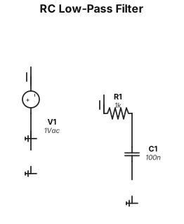
A simple RC low-pass filter with a 1 kΩ resistor and 100 nF capacitor
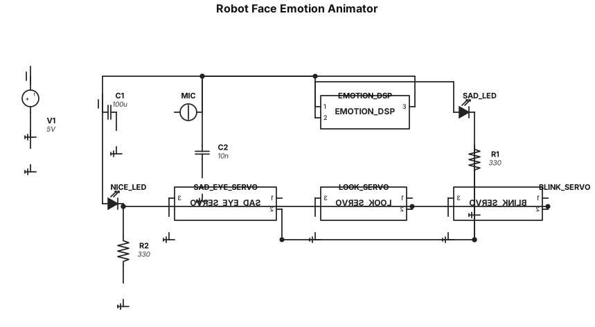
A board for animating facial features: when I say something sad, sadness appears on the robot's face, and when I say something nice, the face brightens, looks around, and blinks.
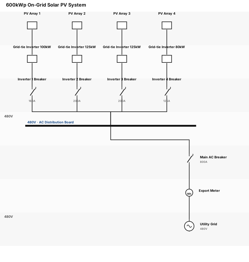
600kWp on grid solar SLD with 4 inverters 100kW, 125kW X 2 and 80kW. show acdb also
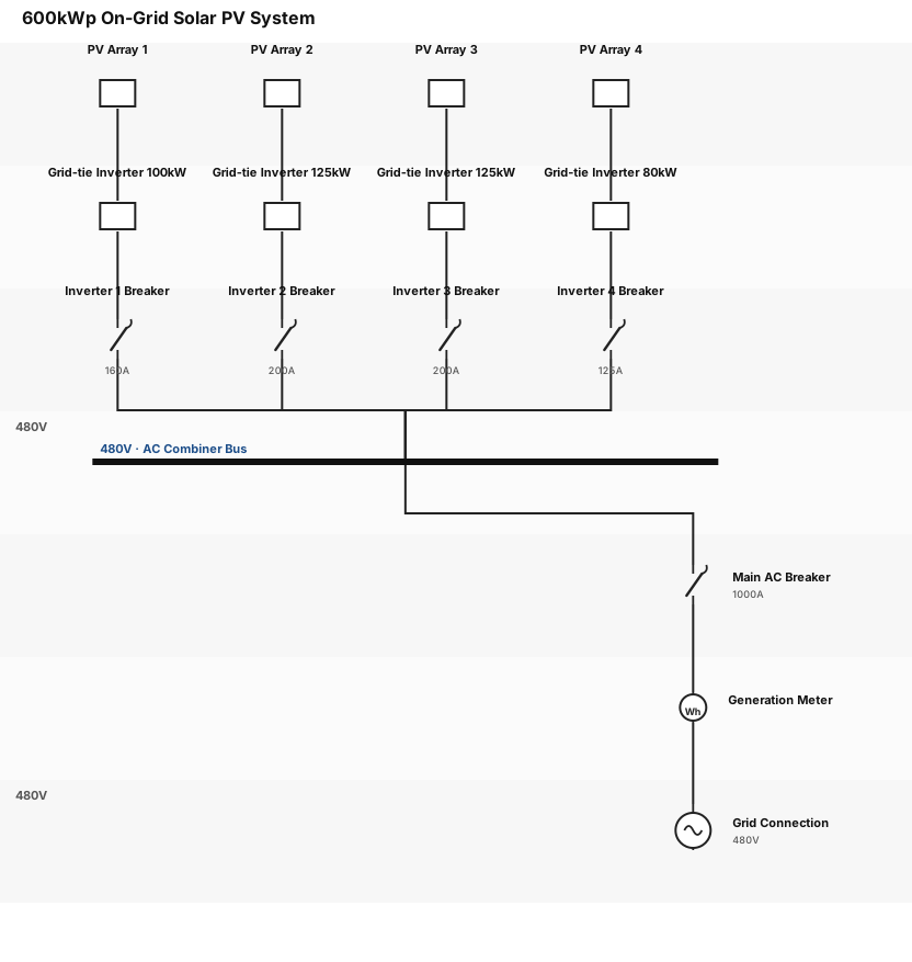
600kWp on grid solar SLD with 4 inverters 100kW, 125kW X 2 and 80kW

Öğrenme psikolojisi kuramları bana tek tek özellikleri ile içeren ve kurucuları kim kurucuların görselleri yani bu karikatür gibi de olabilir daha sonra bu öğrenme psikolojik kuramlarına mesela atıyorum bilimsel koşulma tepki sen koçuma bağlı hocam dikkatli değil yani bunların kurallarını kurallarını açıklayan bir tablo yani görsel tablo yapacaksın
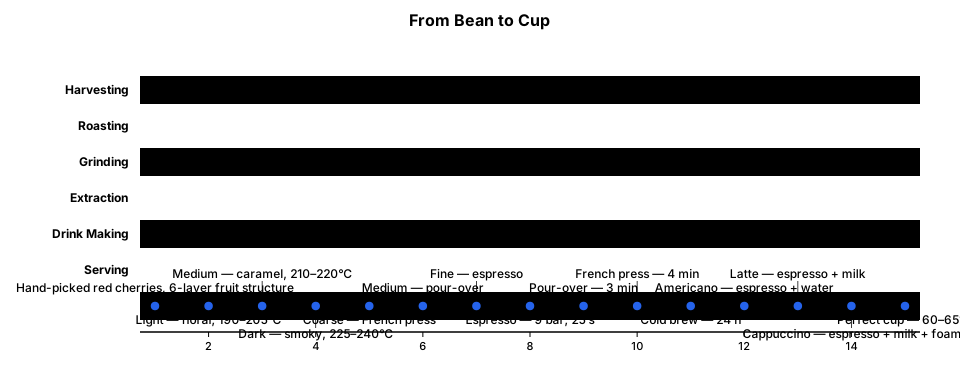
Create a vertical timeline infographic about coffee making process. Title: "From Bean to Cup" Main timeline steps: Harvesting – hand-picked red cherries, 6-layer fruit structure Roasting – 3 levels: Light (floral, 190–205°C), Medium (caramel, 210–220°C), Dark (smoky, 225–240°C) Grinding – coarse (French press), medium (pour-over), fine (espresso) Extraction – espresso (9bar, 25s), pour-over (3min), French press (4min), cold brew (24h) Drink Making – Americano (espresso+water), Latte (espresso+milk), Cappuccino (espresso+milk+foam) Serving – perfect cup at 60–65°C Style: warm brown tones, clean, modern
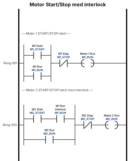
2 motorer betjenes fra hver sin START-STOP kontakt. Motor nummer 2 må kun kunne starte, når motor nummer I kører. Hvis motor nummer I stoppes, skal motor nummer 2 kunne køre videre.
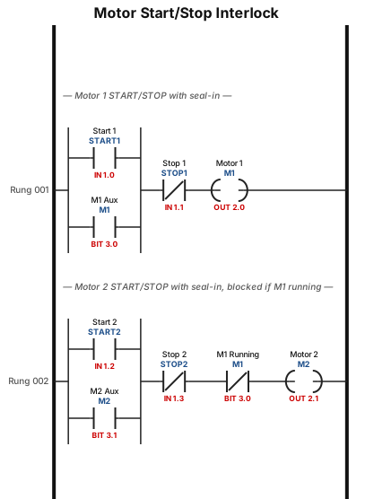
Kan du lave et ladderdiargram ud fra dette?:2 motorer betjenes fra hver sin START-STOP kontakt. Hvis motor nr. 1 startes først, må motor nr. 2 ikke kunne startes. Hvis motor nr. 2 startes først, skal motor nr. 1 kunne startes derefter, uden at udkoble motor nr. 2.
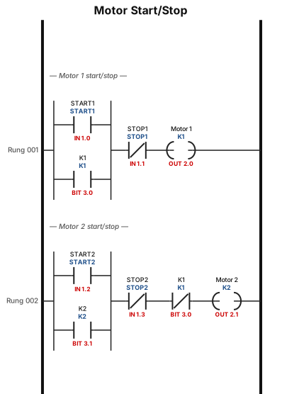
2 motorer betjenes fra hver sin START-STOP kontakt. Hvis motor nr. 1 startes først, må motor nr. 2 ikke kunne startes. Hvis motor nr. 2 startes først, skal motor nr. 1 kunne startes derefter, uden at udkoble motor nr. 2.
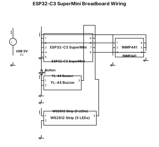
Breadboard wiring, microcontroller ESP32-C3 SuperMini powered via USB 5V. Module 1: INMP441 I2S microphone breakout, 6 pins. VDD to ESP32 3V3. GND to ESP32 GND. SD (data out) to ESP32 GPIO6. WS (word select) to ESP32 GPIO5. SCK (bit clock) to ESP32 GPIO4. L/R to ESP32 GND for left channel. Module 2: YL-44 active buzzer module, 3 pins. VCC to ESP32 VIN 5V. GND to ESP32 GND. IO trigger to ESP32 GPIO10. Module 3: WS2812 addressable LED strip with 5 LEDs in a row. 5V to ESP32 VIN. GND to ESP32 GND. DIN to ESP32 GPIO7. Module 4: momentary push button, 2 legs. One leg to ESP32 GPIO3 with internal pull-up, other leg to ESP32 GND. Wire colors: red for 5V and 3V3 power, black for ground, yellow for I2S signals SD WS SCK, orange for buzzer trigger GPIO10, green for LED data GPIO7, blue for button GPIO3.