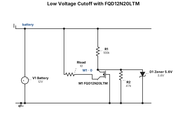
using FQD12N20LTM n-channel Mosfet design a circuit for a low voltage cut-off and on that will turn off the voltage at 6.4 and back on at 7.2 vdc detail each part
NODE ARCHIVE · REAL DIAGRAM BRIEFS
Diagram Examples from Real Visitor Prompts
Browse eligible diagrams shared by FreeDiagram visitors, inspect the exact prompts, and build your own version.
Browse 3261 real creationsCOMMUNITY OUTPUTS · EXACT PROMPTS
Circuit Diagrams
Showing 1–24 of 270. No stock examples or system defaults. Choose a tool, study a real result, then reopen its prompt as your starting point.
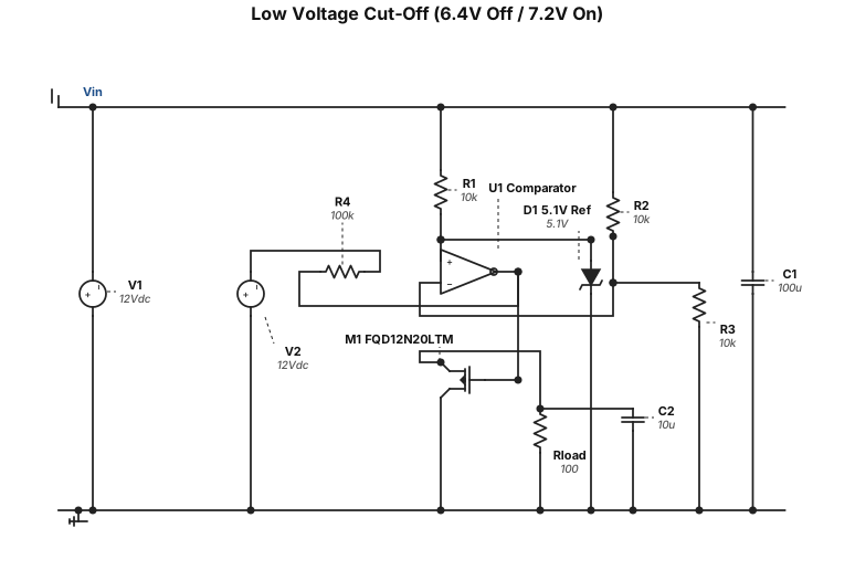
FQD12N20LTM n-channel Mosfet design a circuit for a low voltage cut-off and on that will turn off the voltage at 6.4 and back on at 7.2 vdc
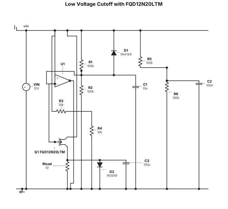
using a FQD12N20LTM n-channel Mosfet design a detailed circuit for a low voltage cut-off and on that will turn off the voltage at 6.4 and back on at 7.2 vdc
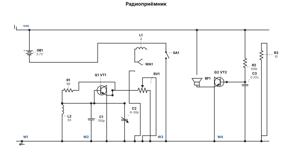
Сгенерируй принципиальную электрическую схему по следующему описанию. Используй стандартные УГО (условные графические обозначения) радиодеталей. Транзисторы NPN (полевые или биполярные, выводы: 1-Эмиттер, 2-База, 3-Коллектор). Компоненты: VT1, VT2 - биполярные NPN транзисторы. L1 - катушка связи (3-5 витков). L2 - контурная катушка (50-60 витков). C1 - конденсатор 150 пФ. C2 - подстроечный конденсатор 8-30 пФ (соединен параллельно C1). R1 - резистор 1 МОм. R2 - резистор 100 кОм. R3 - резистор 10 Ом. RV1 - потенциометр 10 кОм. C3 - конденсатор 0.22 мкФ. WA1 - антенна. BF1 - наушники. SA1 - выключатель. GB1 - источник питания (аккумулятор 3.7В). Соединения: 1. WA1 подключена к первому выводу L1. 2. Второй вывод L1 не подключен (висит в воздухе). 3. L2 и параллельная цепь (C1 || C2) образуют контур. Первый вывод контура подключен к База VT1. Второй вывод контура подключен к Эмиттер VT1. 4. R1 включен между Базой VT1 и Коллектором VT1. 5. Коллектор VT1 подключен к первому крайнему выводу RV1. 6. Второй крайний вывод RV1 подключен к общей минусовой шине. 7. Средний вывод (движок) RV1 подключен к первому выводу C3. 8. Второй вывод C3 подключен к Базе VT2. 9. R2 включен между Базой VT2 и плюсовой шиной питания. 10. Коллектор VT2 подключен к первому выводу BF1. 11. Второй вывод BF1 подключен к плюсовой шине питания. 12. Эмиттер VT2 подключен к первому выводу R3. 13. Второй вывод R3 подключен к общей минусовой шине. 14. Эмиттер VT1 подключен к общей минусовой шине. 15. Плюс GB1 подключен к плюсовой шине питания (к BF1 и R2). 16. Минус GB1 подключен к одному контакту SA1. 17. Второй контакт SA1 подключен к общей минусовой шине (к Эмиттеру VT1, R3 и RV1).
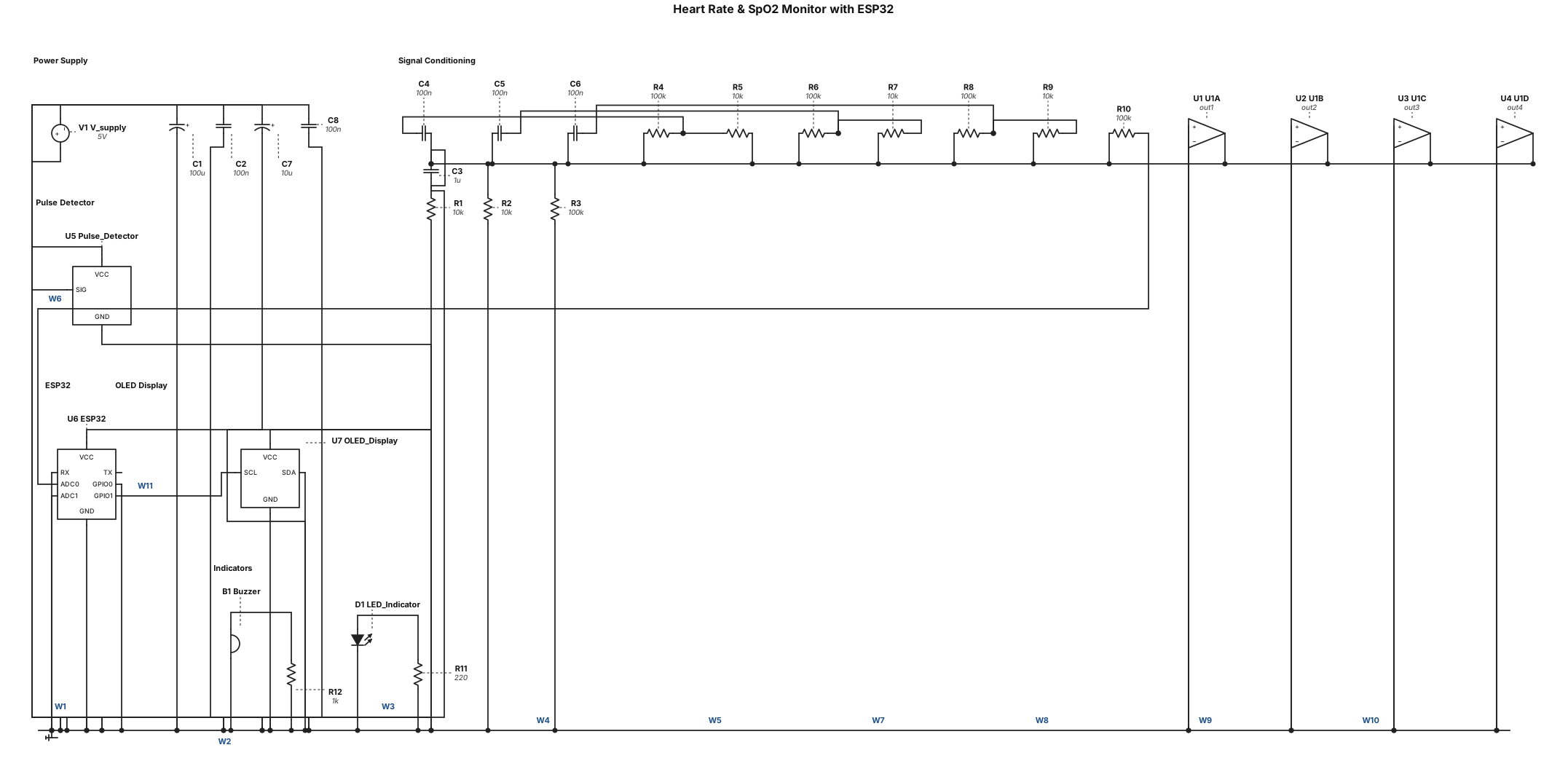
generate the mentioned heart beat modulator using an op amp and esp32 along with the other needed components to show the heart beat waves along with bpm on a led display and oxygen levels also we are using a ready pulse detector
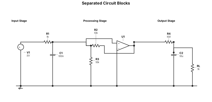
The circuit looks quite right. Can you separate visually the different circuits more from each other, so that i can see the inputs and outputs of the different boxes in wich the circuits shall go?
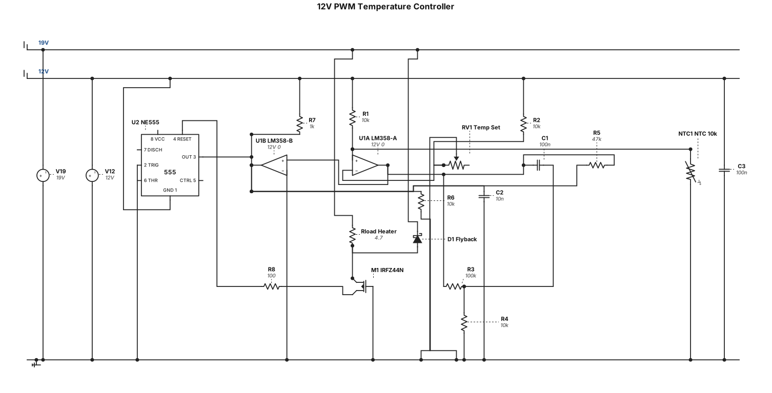
Hello. I want to create a Circuit to heat up a heating element (Resistor). The temperature of the resistor shall be measured via a thermistor and read in by an op amp. Maybe this should be a quad-op amp. The op amp should calculate the voltage for the next circuit, whitch ist driven by a NE 555 timer, providing a PWM-signal to control another circuit with a MOSFET as an amplifier for the heating element. I want to set a temperature for the heating element via a potentiometer. As an OP-amp i have for example one LM358. Can you make me a diagram with an explanation. Every circuit should later be packed in an individual box. Thank you. The circuits should work with 12 Volts. Only the mosfets Drain-Source Voltage is 19 Volts.
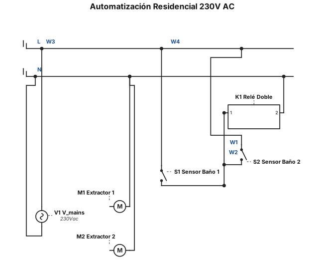
Diseña un esquema eléctrico residencial de automatización a 230V AC. Incluye los siguientes componentes etiquetados: 'Sensor Baño 1', 'Sensor Baño 2', 'Relé Doble' (con bobina A1-A2 y dos contactos independientes NO 1 y NO 2), 'Extractor 1' y 'Extractor 2'. Las salidas de fase de ambos sensores deben conectarse en paralelo al borne A1 de la bobina del relé. El borne A2 va a la línea de Neutro. Conecta la Fase directa a las entradas comunes (COM) de ambos contactos del relé. La salida NO 1 debe alimentar al Extractor 1 y la salida NO 2 debe alimentar al Extractor 2. Conecta el Neutro a todos los componentes."
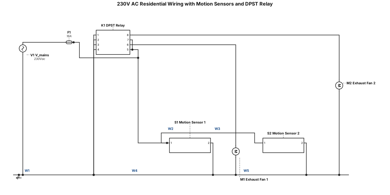
Draw a 230V AC residential wiring diagram. Components: 'Motion Sensor 1', 'Motion Sensor 2', 'DPST Relay' (Double Pole Single Throw relay with coil terminals A1/A2 and two Normally Open contacts), 'Exhaust Fan 1', and 'Exhaust Fan 2'. Connect the switch leg outputs of both Motion Sensor 1 and Motion Sensor 2 in parallel to the relay coil terminal A1. Connect coil terminal A2 to the Neutral line. Connect direct Hot/Line to the common terminals of both relay contacts. Connect contact NO 1 to Exhaust Fan 1, and contact NO 2 to Exhaust Fan 2. Connect Neutral to all components.
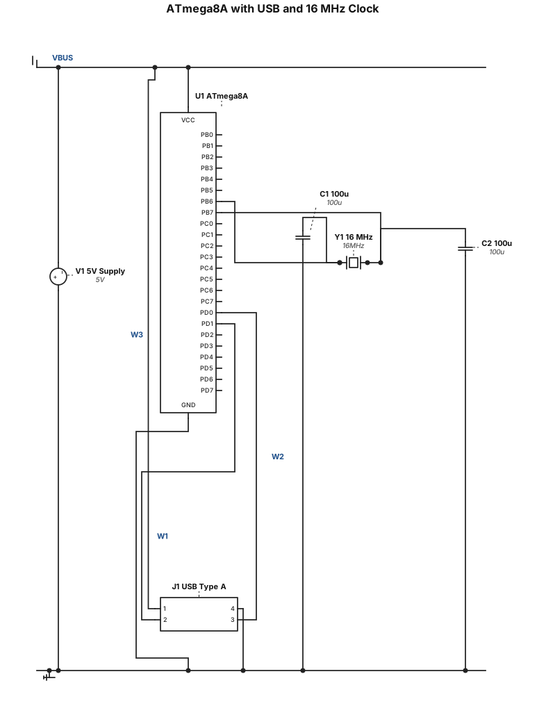
add an atmega8a microcontroller and a 16 MHz quartz clock with two 100 microfarad disk capacitors, a type A USB input, and 5V power supply and connect the USB pins to the microcontroller
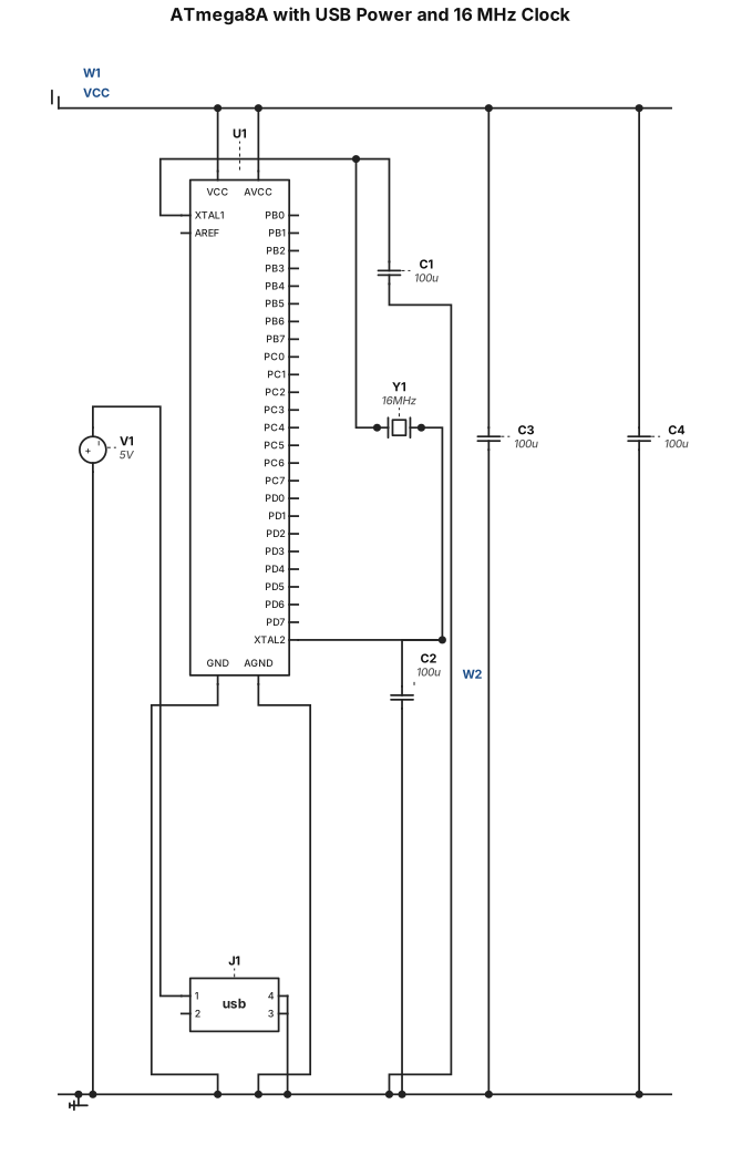
add an atmega8a microcontroller and a 16 MHz quartz clock with two 100 microfarad disk capacitors, a type A USB input, and 5V power supply
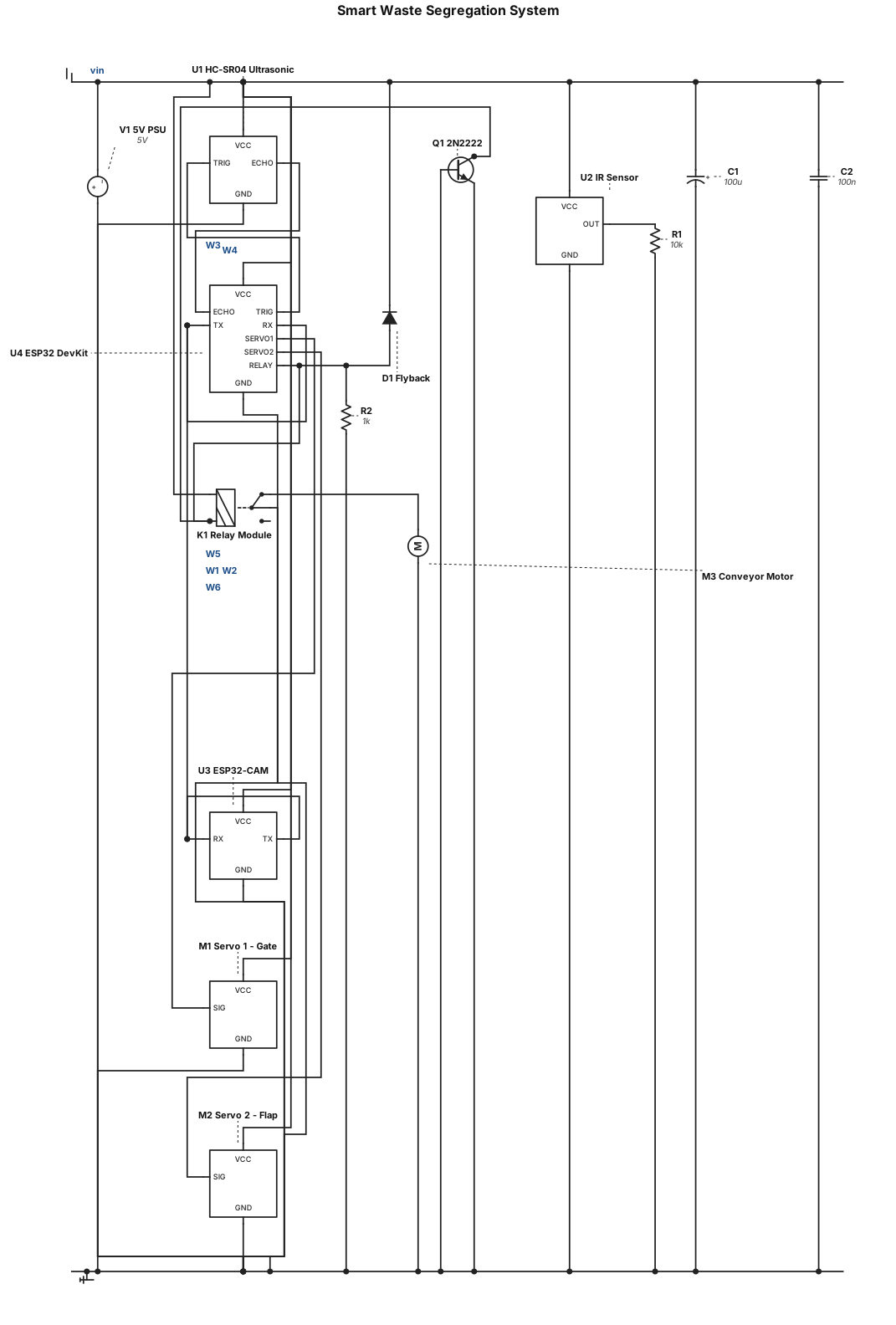
Hi, I am working on a Smart Waste Segregation Project. My Project Idea The main aim of my project is to automatically identify plastic and non-plastic waste and separate them into different sections. Components I Have - ESP32 DevKit – main controller - ESP32-CAM – captures the image of the waste - Ultrasonic sensor – detects the object/distance - IR sensor – detects the presence of an object - 2 Servo motors – moves the waste to the correct section - Relay module - Breadboard - Jumper wires - 5V power supply How I Want It to Work 1. A waste item is placed into the system. 2. The ultrasonic/IR sensor detects the object. 3. The ESP32-CAM captures its image. 4. The system identifies whether it is plastic or non-plastic. 5. The ESP32 receives the result. 6. Based on the result, the servo motor moves the waste to the correct section. 7. Then the system is ready for the next item. Important Requirement If multiple plastic and non-plastic items are put together, I want the system to process them one by one, so that the camera can identify each item properly. I need help with the complete circuit connection, ESP32 + ESP32-CAM communication, image classification method, coding, and the mechanical separation mechanism. My final goal is to make a proper working model where: Waste detected → Image captured → Plastic/Non-Plastic identified → Automatically separated.
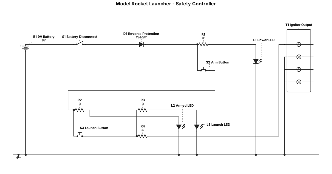
Design a simple circuit for a model rocket launcher with wired remote with battery disconnect, button safety and lights for each state then final ignition button with launch light Make a simplifies version that can be soldered by a notice with minimal parts and experience Show all steps along the way and the renders of diagrams as they are generated. Create electrical circuit diagram and solder guide with diagram or graphics overview and step by step. Then package everything together for sharing
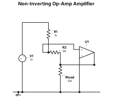
A non-inverting op-amp amplifier circuit with a gain of 10, using a 1 kΩ input resistor and a 9 kΩ feedback resistor
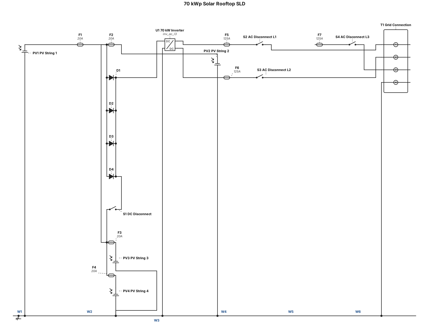
i need a 70 kwp solar Rootop sld
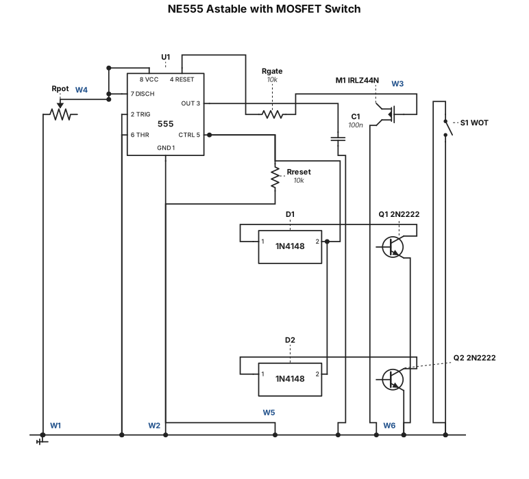
NE555 timer astable circuit with MOSFET switch. Components: NE555 IC (8-pin), IRLZ44N N-MOSFET, two 2N2222 NPN transistors, four 1N4148 diodes, one WOT switch. 555 pins 2+6 to 47k pot and 100nF cap. Pin 3 through 10k to MOSFET gate. Pin 4 pulled to 5V through 10k, two diodes from transistor collectors into pin 4. MOSFET drain to IGT_IN, source to IGT_OUT and GND.
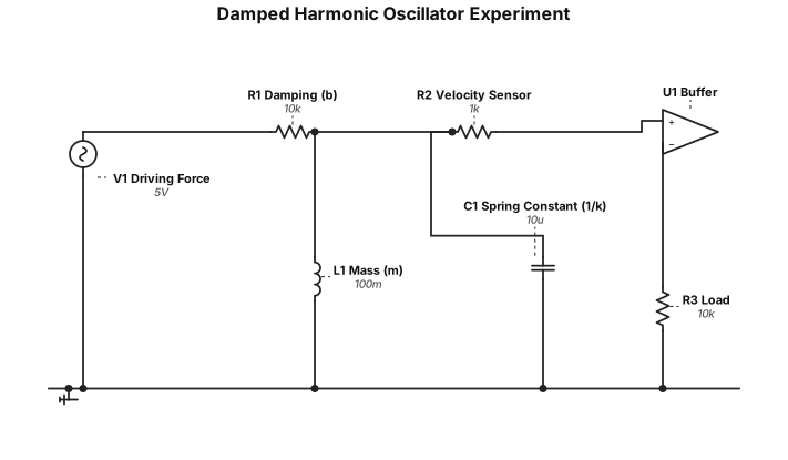
a set up for a damped harmonic oscillator experiment using springs
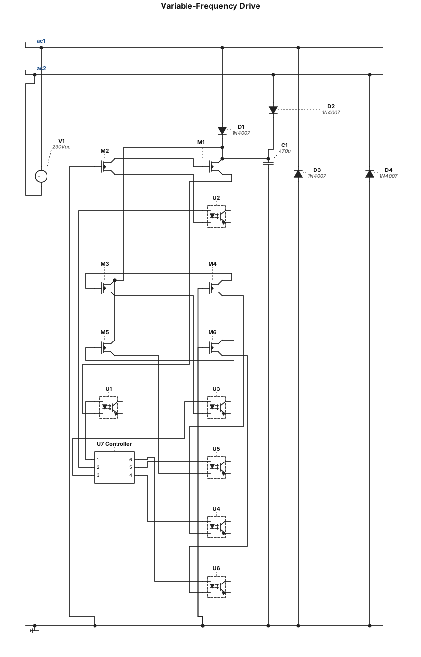
variable-frequency drive consists of a bridge rectifier , six N-channel MOSFETs , gate drivers, and optocouplers. A controller generates six PWM signals to control the switching of the MOSFETs.
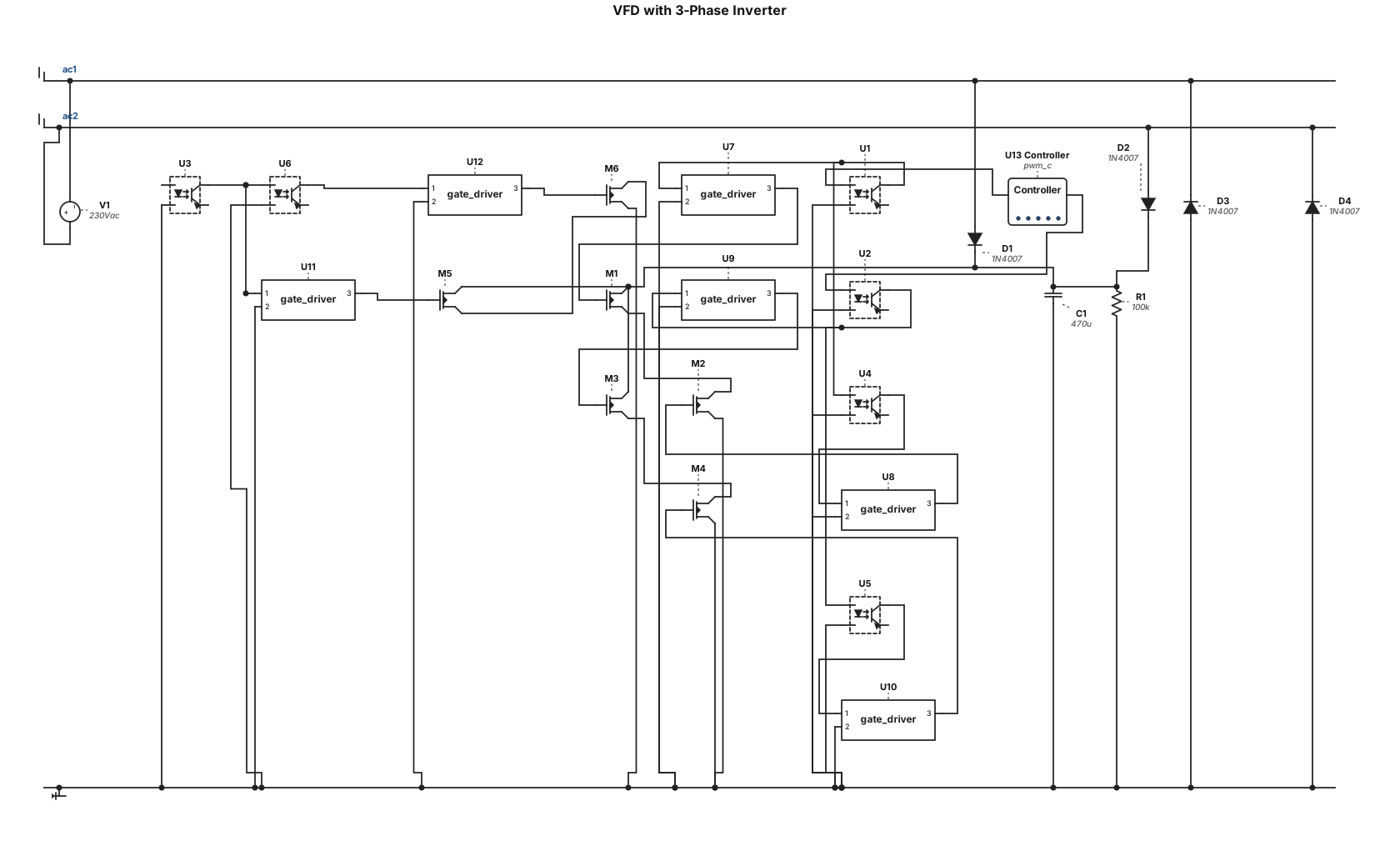
a vfd circuit with a bridge rectictifier , a six n-channel mosfets inverter bridge, gate drivers, optocouplers connected to a controller that outputs 3 pmw signals
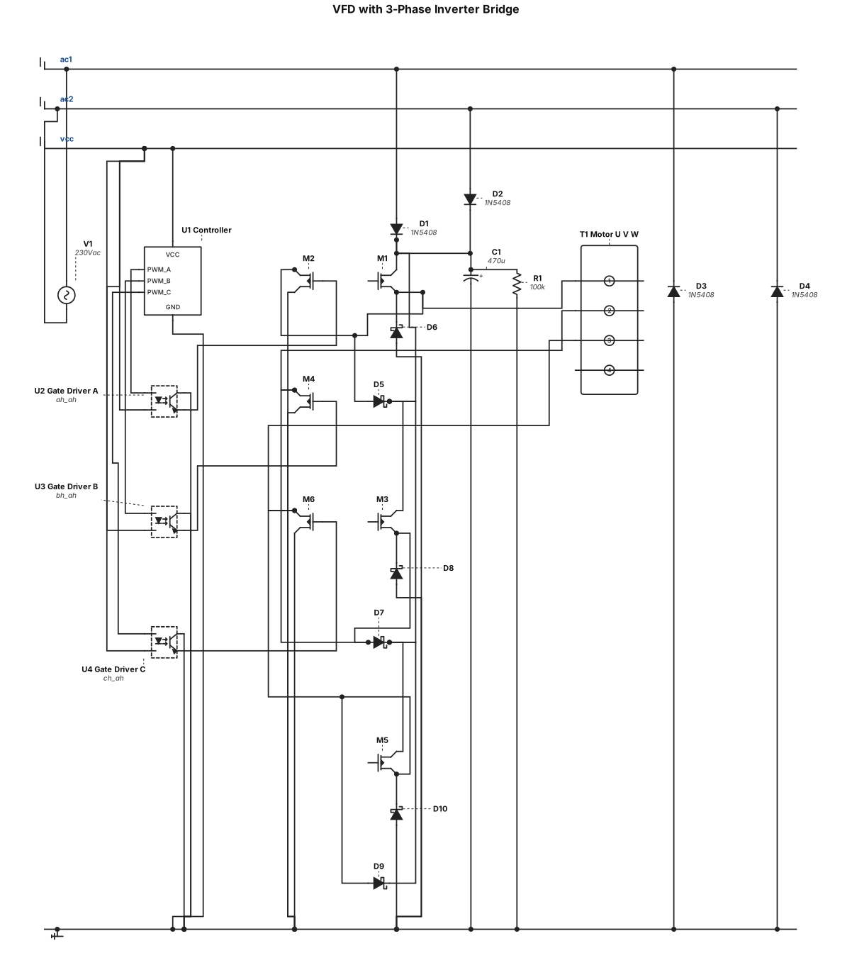
a vfd circuit with a bridge rectictifier , a six n-channel mosfets inverter bridge, gate drivers, optocouplers connected to a controller that outputs 3 pmw signals one per phase
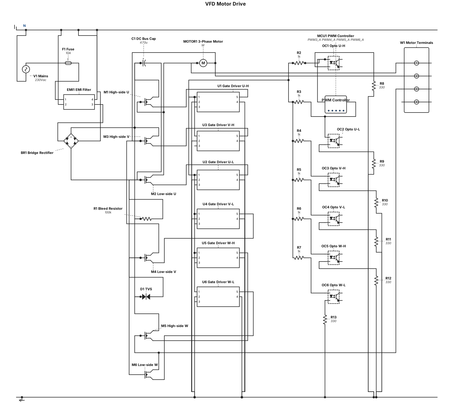
a vfd circuit with a bridge rectictifier , a six n-channel mosfets inverter bridge, gate drivers, optocouplers connected to a controller that outputs six pmw signals
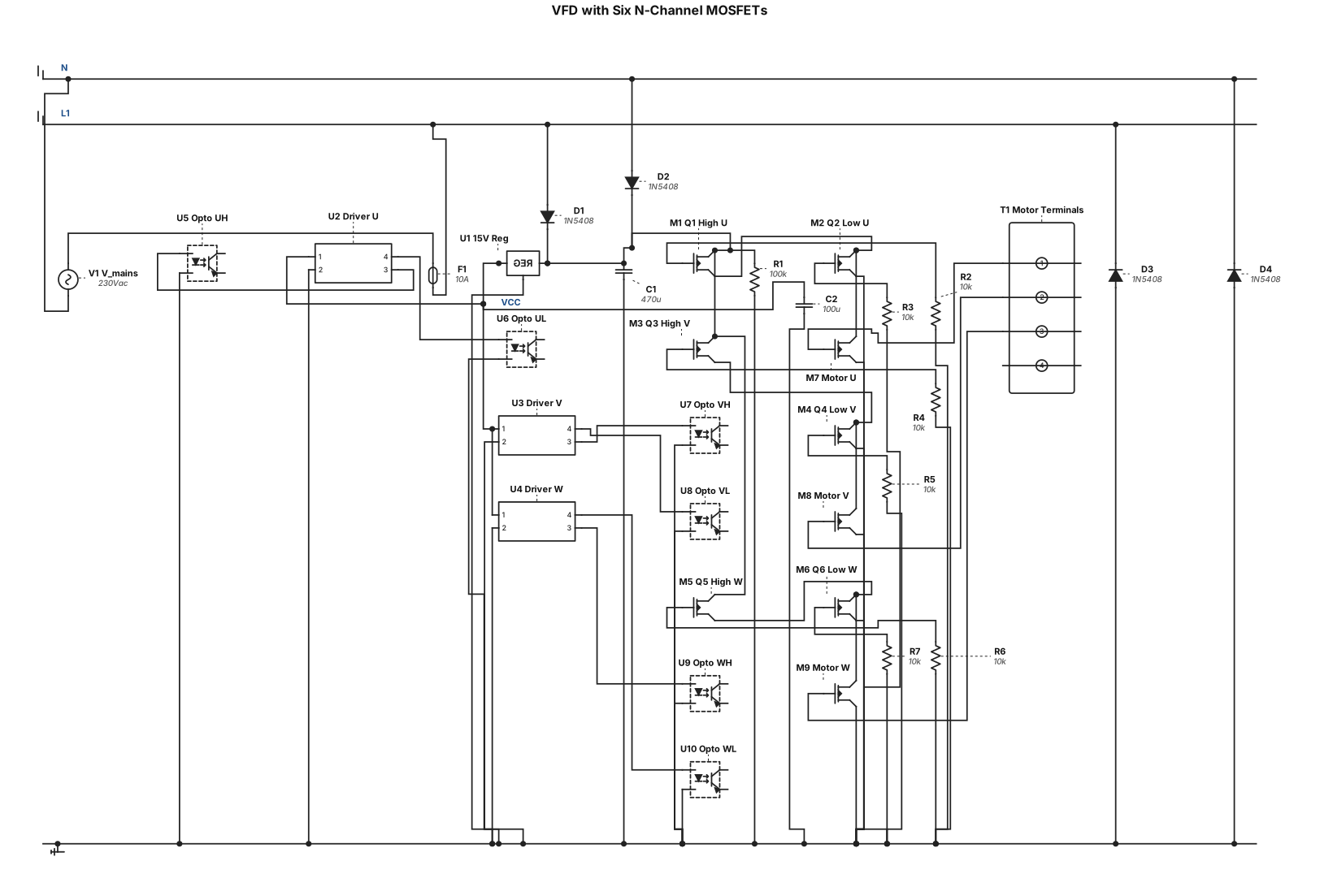
a vfd circuit with a six n-channel mosfets with a bridge rectictifier , gate drivers and optocouplers
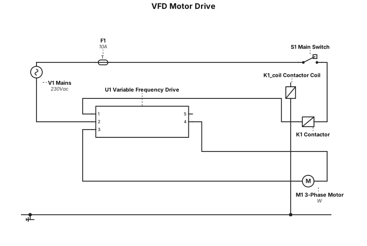
a vfd circuit
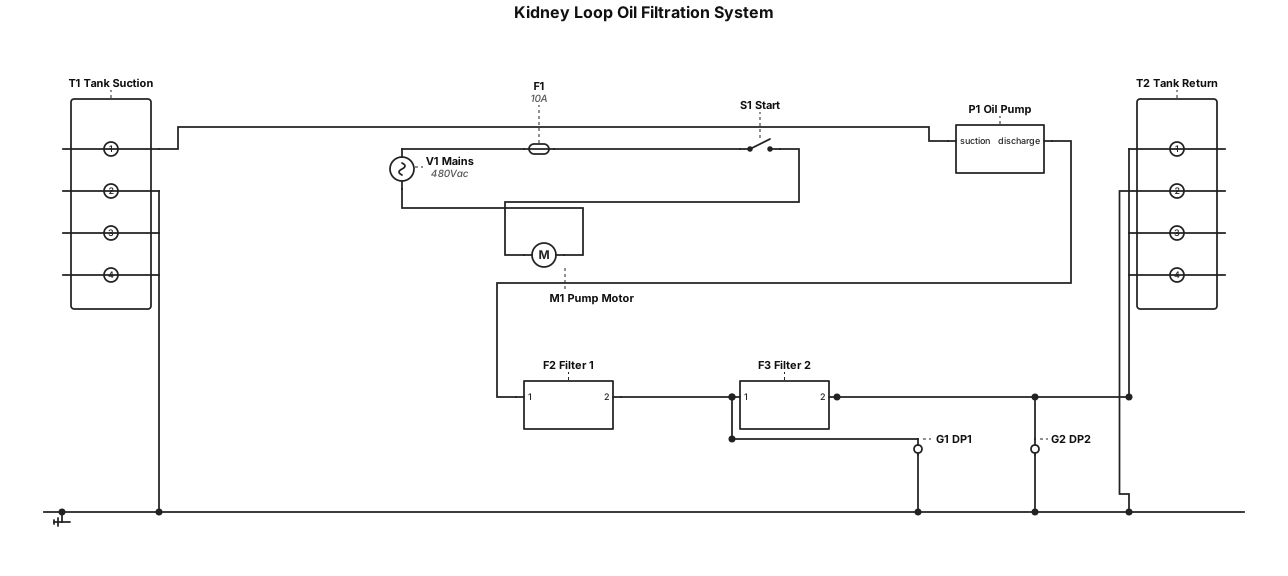
A kidney loop oil filteration sysytem with two particulate filter