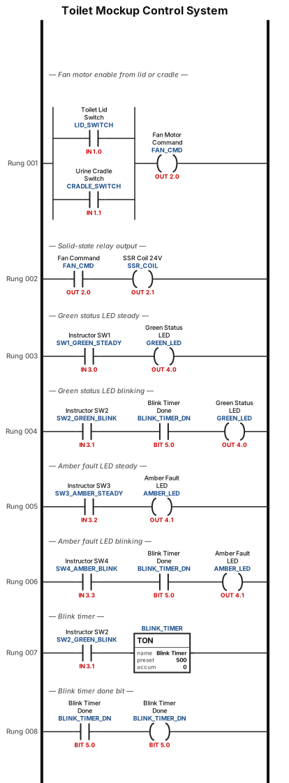
A control wiring and logic diagram for a toilet mockup system: opening the toilet lid switch or lifting the urine cradle switch commands an Arduino to energize a 24V fan motor through a solid-state relay, while a 4-switch instructor box sets the Green status and Amber fault LEDs to steady, blinking or off states, powered by isolated 5V logic and 24V motor power rails.
NODE ARCHIVE · REAL DIAGRAM BRIEFS
Diagram Examples from Real Visitor Prompts
Browse eligible diagrams shared by FreeDiagram visitors, inspect the exact prompts, and build your own version.
Browse 3261 real creationsCOMMUNITY OUTPUTS · EXACT PROMPTS
Ladder Logic
Showing 1–24 of 57. No stock examples or system defaults. Choose a tool, study a real result, then reopen its prompt as your starting point.
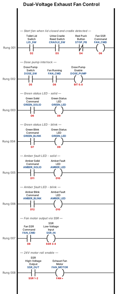
This system diagram illustrates a dual-voltage electrical control architecture centered around an microcontroller and a DC power supply. The power supply is divided into two galvanically isolated domains: a low-voltage 5VDC that powers the Arduino board's 5V/GND header pins and the UBL 1100 4-Switch Box, and a high-voltage +24 VDC motor rail (Channel 1) dedicated solely to running a heavy-duty exhaust fan . At the center, four dry-contact field switches on the toilet mockup the toilet lid switch (D2), urine cradle reed switch (D3), red push button (D4), and dose pump switch (D5) connect between their designated Arduino digital pins and a shared 5VDC common ground bus. The UBL 1100 instructor switch box sends four active-high signal wires into Arduino pins D6 (Green Solid), D7 (Green Blink), D11 (Amber Solid), and D12 (Amber Blink), which dynamically command a Green Status LED on pin D9 (via a series 330" " Ωresistor) and an Amber Fault LED on pin D10 (via a series 510" " Ωresistor) [1]. Completing the high-power circuit, Arduino output pin D8 and GND connect across the low-voltage input terminals (Pins 3 & 4) of a DC-to-DC Solid-State Relay (SSR), while the relay's high-voltage output terminals (Pins 1 & 2) switch the continuous +24.0" V DC" power feed to the Red wire (FAN +) of the fan motor, whose Black wire (FAN -) returns directly to the isolated 24" V" power supply ground.

I have a Mitsubishi FX5U 32M PLC, an MGS1600GY magnetic sensor, 2 BLVD KRD Type R motor drivers, a motor, and 2 BLHM5100KC GFS motors. I’m going to assemble them as an AGV. With your intelligence, make the ladder diagram in detail and make sure the motor PID works well.
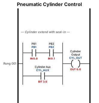
A ladder logic program for a pneumatic cylinder: when PB1 input 0 , output is 0, if pb2 is 0 ,output is 0,when pb1 is 1,output is 0,when pb2 is 1,output is 0,use AND gate with seal in
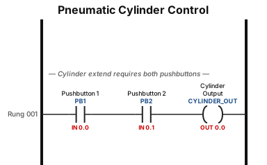
A ladder logic program for a pneumatic cylinder: when PB1 input 0 , output is 0, if pb2 is 0 ,output is 0,when pb1 is 1,output is 0,when pb2 is 1,output is 0,use AND gate
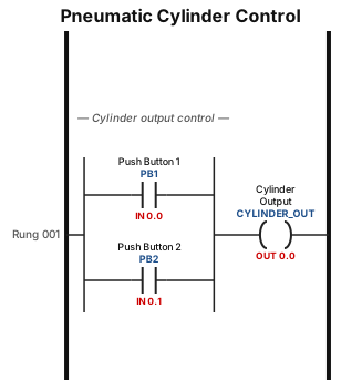
A ladder logic program for a pneumatic cylinder: when PB1 input 0 , output is 0, if pb2 is 0 ,output is 0,when pb1 is 1,output is 0,when pb2 is 1,output is 0,use OR gate
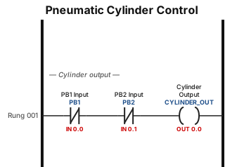
A ladder logic program for a pneumatic cylinder: when PB1 input 0 , output is 0, if pb2 is 0 ,output is 0,when pb1 is 1,output is 0,when pb2 is 1,output is 0
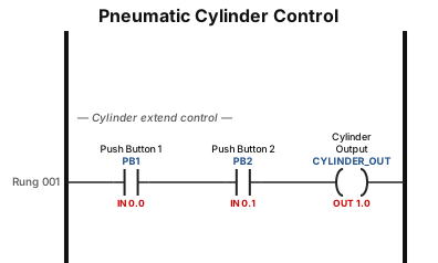
A ladder logic program for a pneumatic cylinder: when 2 PB input 1 , output is 1,if pb1 is 0,out is 0
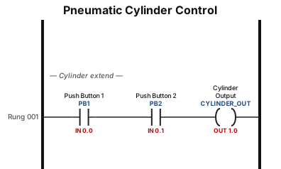
A ladder logic program for a pneumatic cylinder: when 2 PB input 1 , output is 1
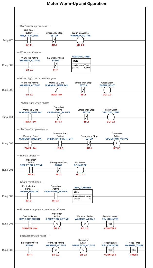
The system process takes 10 seconds to warm up and should display a green light during warm up. The warm up process should be started by pressing a button on the HMI screen. Once the warm up process is complete, a yellow light should inform the operator the system is ready. The operator is then required to push a button to start operation of a DC motor. The photoelectric sensor will count the number of revolutions completed by the motor shaft. The process is ended once ten revolutions are completed. To run the next process, the system will need to undergo warm up again. An emergency stop button should be included in the system, this should terminate any running process when pressed.
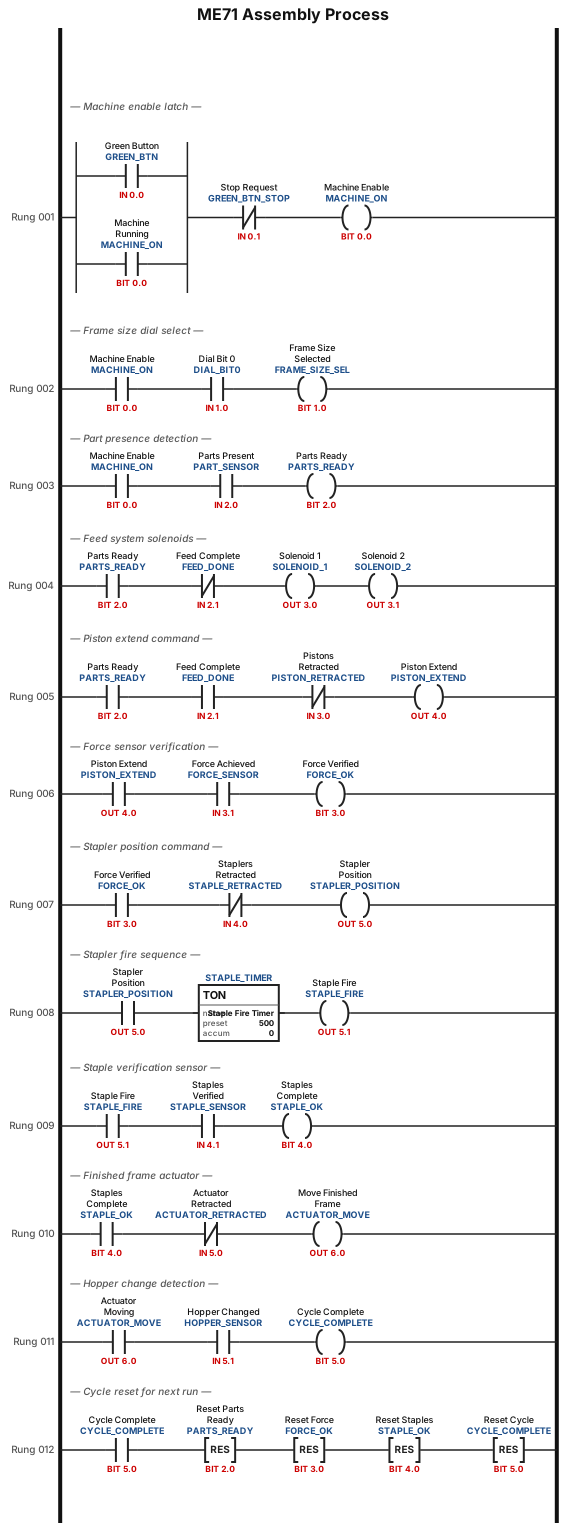
A ladder logic program for a conveyor belt system: start button seals in the motor, a ME71 Assembly Process Written Beforehand: Set Dial to 0 or 1 to determine frame size 1st: Green Button turns on the machine (also works as a stop switch, if needed) 2nd: Green Button sends signal to sensors which determine if the machine has parts or is empty (if it has stuff then it passes a 1 signal) and if it passes then two solenoids are powered and a feed system brings the assembly pieces into place for the pistons 3rd: Pneumatic pistons push the frames into place and a sensor detects the approprtiate force was pushed onto the frame 4th: Stapler guns are moved into place and fire at 4 points then retracted 5th: Sensor determines the frame has been stapled then an actuator moves the finished frame out of the assembly 6th: A final sensor determines there has been a change in the hopper (finished product area) mass or visual marker and runs the cycle again
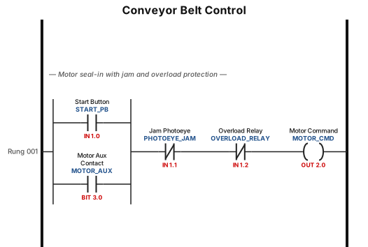
A ladder logic program for a conveyor belt system: start button seals in the motor, a photoeye stops the belt when a jam is detected, and an overload relay trips the circuit
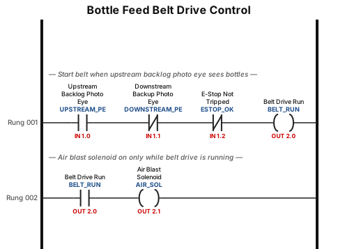
The installation of a photo eye upstream prior to the belt drive will trigger the belt drive to start / stop to maintain a bottle prime for the inverter which will ensure consistent flow of containers through the Inverter. The photo eye would work in the manner that once a required back log of containers is met, the belt drive is triggered to begin feeding containers into the inverter. The belt drive would run continuously until the upstream photo eye is no longer seeing bottles. When the upstream photo eye doesn’t see bottles, the belt drive will stop rotating until the photo eye sees containers to identify that the required back log has been achieved. A second photoeye will be installed downstream of the inverter and act as a bottle backup sensor which will stop the belt drive if the conveyor is backing up with bottles due to the filler stopping. The control system will also include an air solenoid that controls the air blast so that it is not continuously blowing. The air will only be on while the belt drive is running.
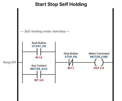
Start Stop Self Holding
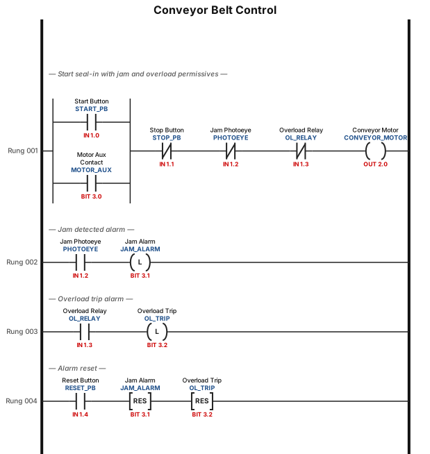
A ladder logic program for a conveyor belt system: start button seals in the motor, a photoeye stops the belt when a jam is detected, and an overload relay trips the circuit
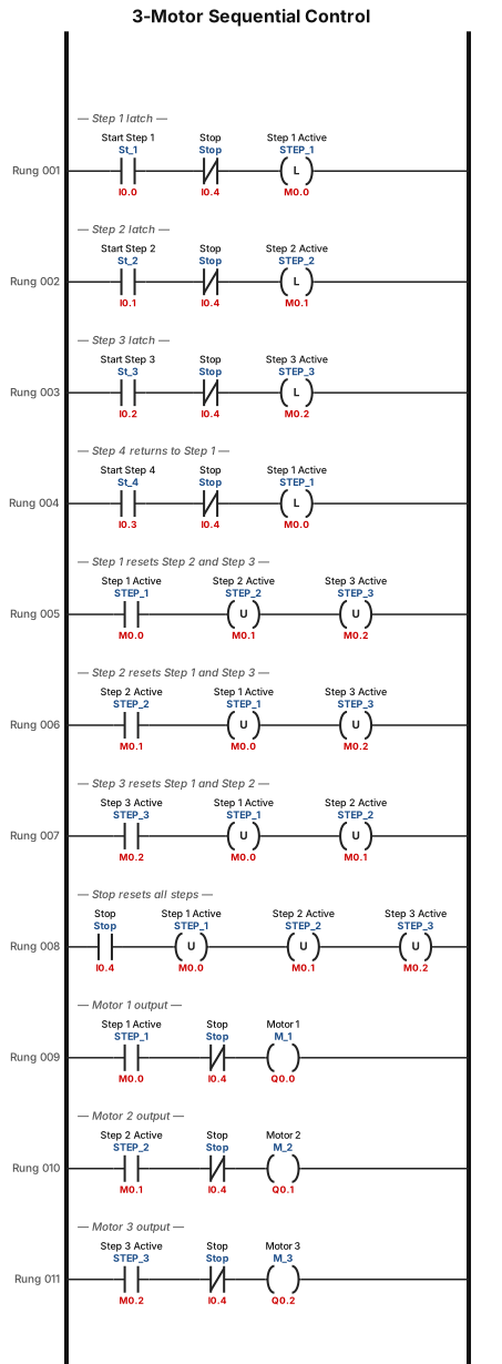
A ladder logic program forCreate a Siemens TIA Portal Ladder Logic (LAD) program for a sequential control system with 3 motors: Motors: M_1, M_2, M_3 Inputs: St_1 = Start push button for sequence step 1 St_2 = Start push button for sequence step 2 St_3 = Start push button for sequence step 3 St_4 = Start push button for sequence step 4 Stop = Emergency/Stop push button Sequence: 1. When St_1 is pressed: M_1 = ON M_2 = OFF M_3 = OFF 2. When St_2 is pressed: M_1 = OFF M_2 = ON M_3 = OFF 3. When St_3 is pressed: M_1 = OFF M_2 = OFF M_3 = ON 4. When St_4 is pressed: Return to step 1: M_1 = ON M_2 = OFF M_3 = OFF The sequence must operate cyclically: Step 1 → Step 2 → Step 3 → Step 1 → ... At any time, when Stop is pressed: M_1 = OFF M_2 = OFF M_3 = OFF and the sequence is reset. Use internal memory bits for the sequence states if needed. Implement the logic as Siemens TIA Portal LAD using contacts, coils, SET/RESET or equivalent latching logic. Make sure only one motor is ON in each sequence step.
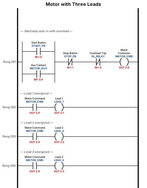
A ladder logic program for a motor with three leads
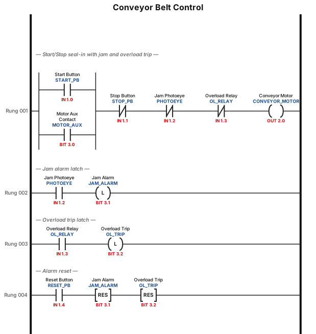
A ladder logic program for a conveyor belt system: start button seals in the motor, a photoeye stops the belt when a jam is detected, and an overload relay trips the circuit
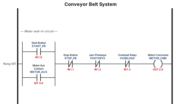
A ladder logic program for a conveyor belt system: start button seals in the motor, a photoeye stops the belt when a jam is detected, and an overload relay trips the circuit
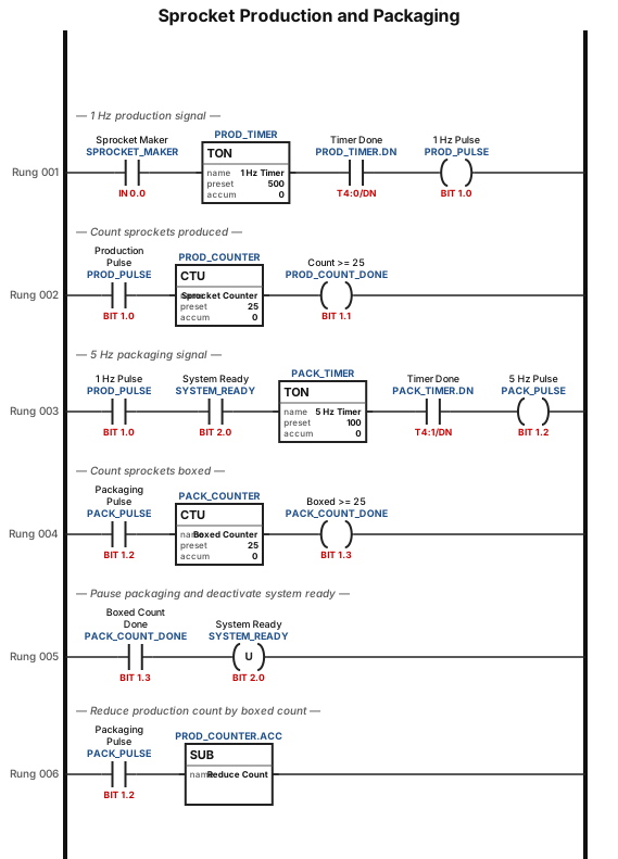
As long as a specific discrete input (SPROCKET_MAKER) is active, a continuous 1 Hz periodic signal is produced. Each sprocket produced will increment a counter. When the number of sprockets meets or exceeds 25, the counter sends an active signal. The count can exceed 25. As long as the incoming 1 Hz discrete signal is active, a continuous 5 Hz periodic signal is produced. The 5 Hz periodic signal will not be produced if a specific discrete signal (SYSTEM_READY) is inactive. Once 25 sprockets have been boxed, the periodic signal pauses and the SYSTEM_READY state changes to inactive. The SYSTEM_READY state must be manually changed from inactive to active before the packaging can continue. Each sprocket boxed reduces total count from the first counter.
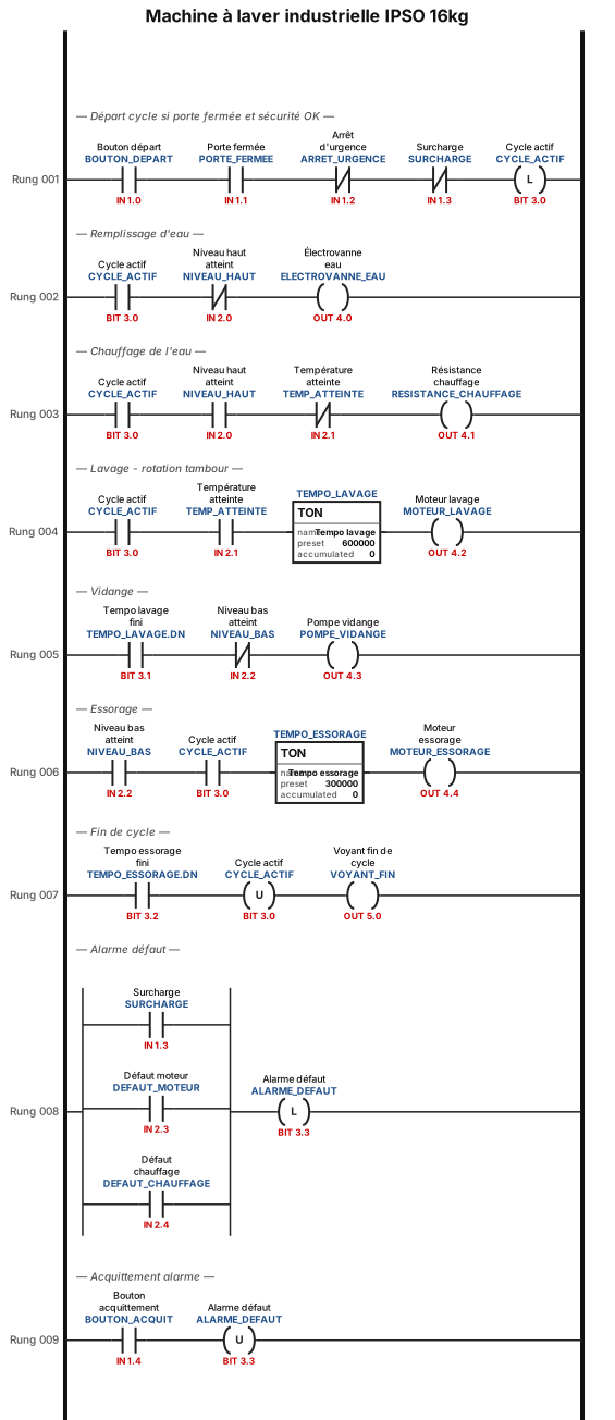
plc pour machine a laver indutrielle ipso 16kg
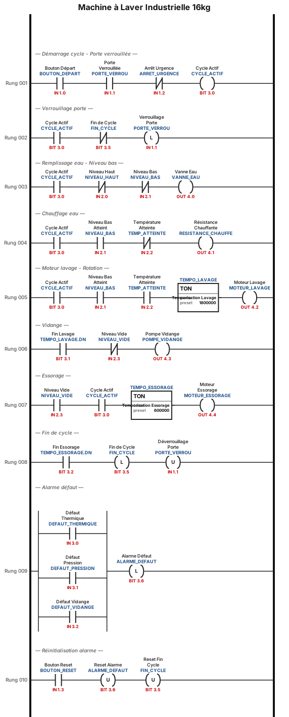
machine a laver industriel 16kg
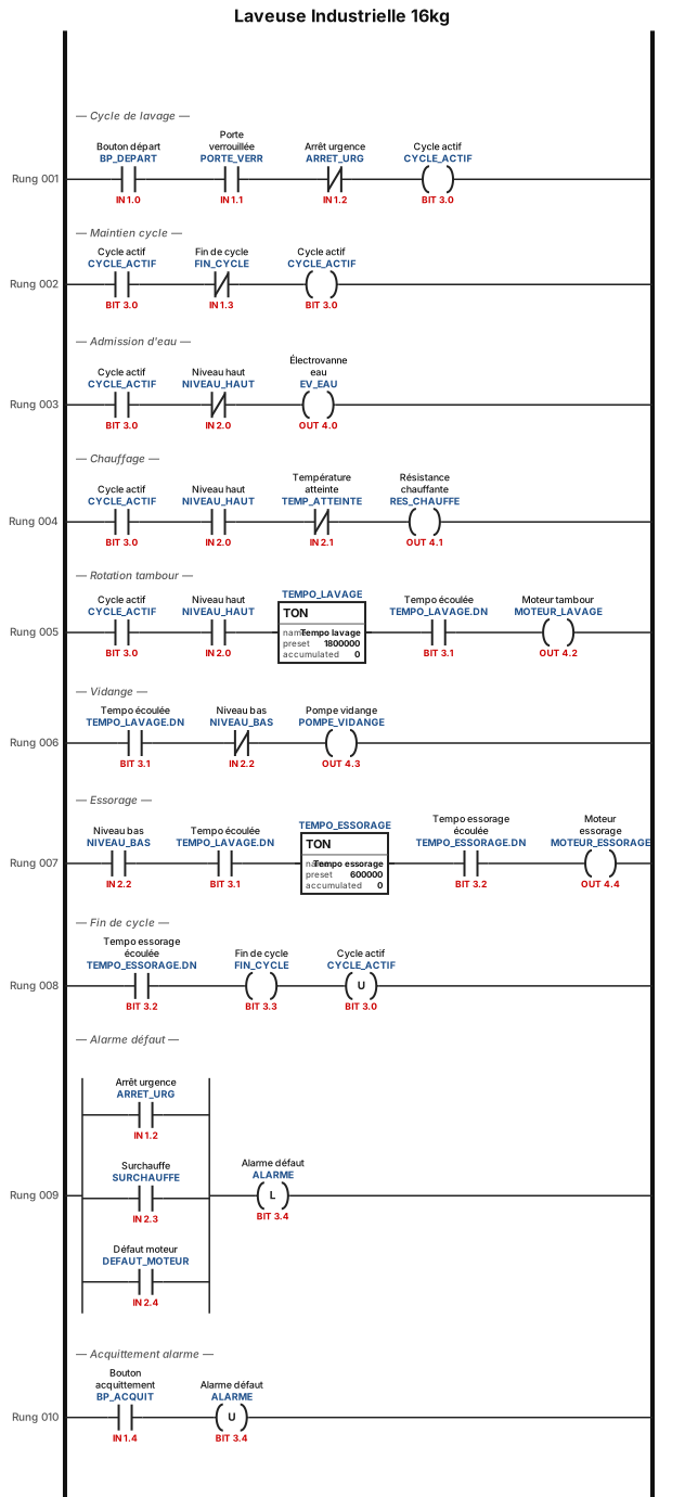
laveuse industriel 16kg
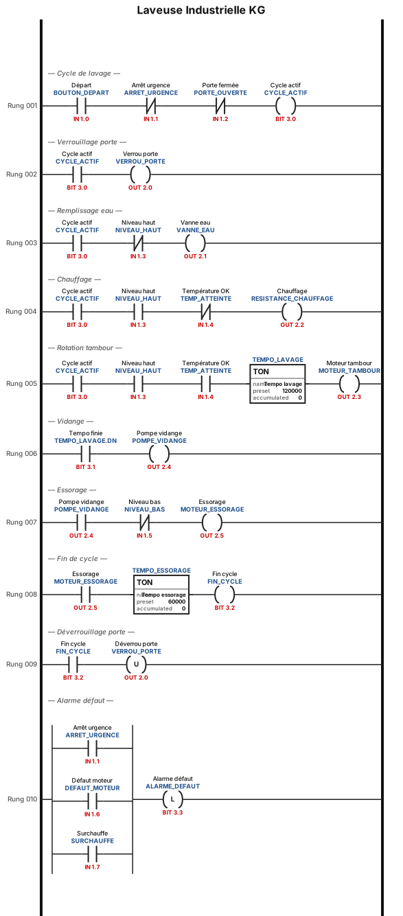
laveuse industriel kg