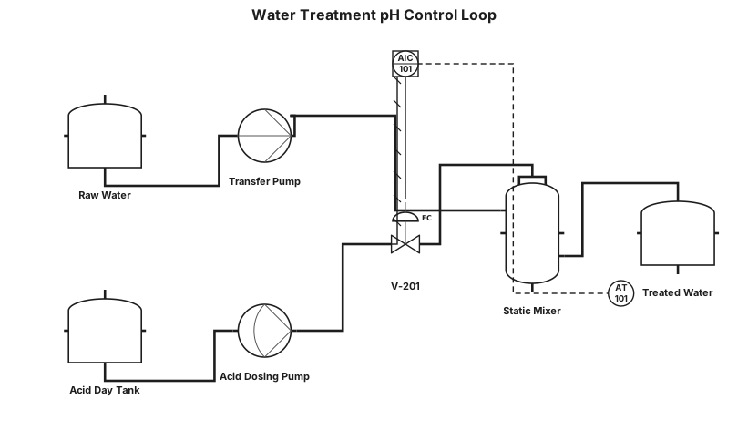
Water treatment loop with pH control and dosing pump
NODE ARCHIVE · REAL DIAGRAM BRIEFS
Diagram Examples from Real Visitor Prompts
Browse eligible diagrams shared by FreeDiagram visitors, inspect the exact prompts, and build your own version.
Browse 3261 real creationsCOMMUNITY OUTPUTS · EXACT PROMPTS
Pid
Showing 1–24 of 142. No stock examples or system defaults. Choose a tool, study a real result, then reopen its prompt as your starting point.
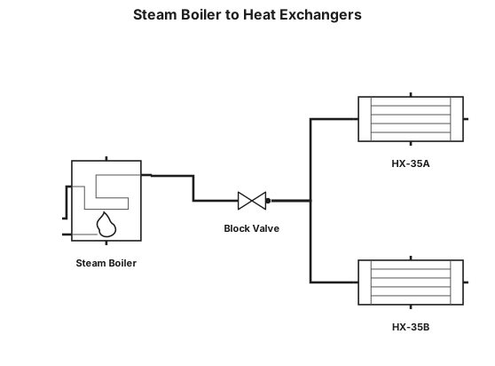
160# steam boiler to a block valve to heat exchangers HX35A/B to process
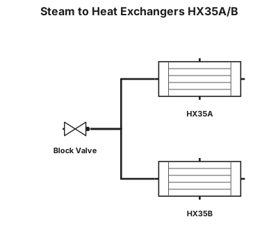
160# steam to a block valve to heat exchangers HX35A/B to process
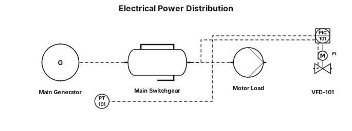
i need electrical diagram
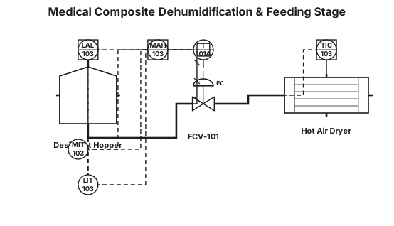
Generate a clean, high-precision ANSI/ISA-5.1-2024 P&ID diagram for a Medical Composite Dehumidification & Feeding Stage. EQUIPMENT: - EQ-HOP-101: Desiccant Hopper (DCS-connected). - EQ-DRY-101: Hot Air Dryer (120.0 °C). - FCV-101: Feeding Control Valve (Fail Closed - FC). INSTRUMENTATION & CLOSED LOOPS (LOOP 103): - LIT-103: Ultrasonic Level Transmitter on EQ-HOP-101 (Setpoint: 80%, Low Alarm LAL-103 < 20%). - TIC-103: PID Dryer Temp Controller for EQ-DRY-101 (Setpoint: 120.0 °C, RTD Pt100). - MIT-103: Moisture Transmitter ISO 15512 in pellets (Setpoint <= 200 ppm, High Moisture Alarm MAH-103 > 200 ppm). SAFETY INTERLOCK (I-101A): - Draw a red dashed safety interlock line from MIT-103 (MAH-103 trigger) to Safety Logic Box [I-101A]. - Connect [I-101A] via red dashed line to close FCV-101 (FC) and disable barrel feeding upon high moisture. CONNECTIONS: - Main Process Line (thick solid black): Granule feed to EQ-HOP-101, through FCV-101 to EQ-DRY-101, discharging to Injection Barrel inlet. - Electrical/DCS Signal (dashed line): LIT-103, TIC-103, MIT-103 to DCS/PLC. - Include ISA legend for line types and FC valve position.
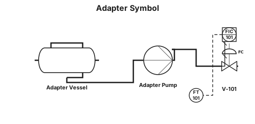
adapter

a pump connected to a 6" pipe. Off of that pipe are 8 connections via T's, with an isolation valve at the connection point, and then a 4" line coming off of it with a sanitary connection at the end. At the end of the header loop back to the inlet of the pump

a pump connected to a 6" pipe. Off of that pipe are 8 connections via T's, with an isolation valve at the connection point, and then a 4" line coming off of it with a sanitary connection at the end

a pump connected to a 4" pipe. Off of that pipe are 8 connections via T's, with an isolation valve at the connection point, and then a 4" line coming off of it with a sanitary connection at the end
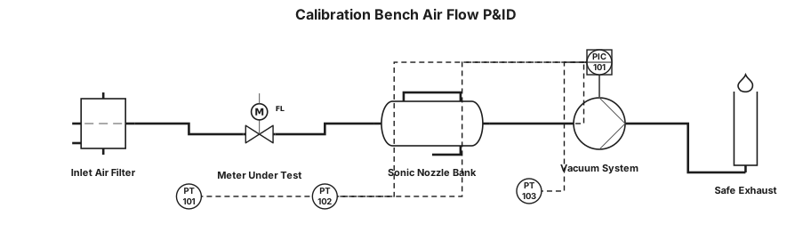
The P&ID shows how air enters the calibration bench, passes through the meter under test, is referenced by the sonic-nozzle bank, and is finally drawn through the vacuum system to safe exhaust.”

A P&ID for a Gas metering and calibration unit where atmospheric air passes the inlet isolation valve and filter, where differential pressure is monitored. It then passes through the straight-run flow conditioner and into the UUT test section. This is where the customer’s meter is installed and secured. Reference — Downstream, the flow reaches the upstream plenum and the 20-nozzle critical-flow bank. The selected calibrated nozzle or nozzle combination establishes the reference flow under controlled pressure and temperature conditions. This is the metrology heart of the system. Vacuum & exhaust — The reference flow then enters the vacuum manifold. The P&ID provides low-flow and high-flow suction branches with blower, non-return and isolation protection. The discharge is routed through the silencer to the safe exhaust. Controls & safety — The PLC/HMI supervises the sequence, measurements and permissives. The design includes pressure, temperature, vibration and other monitoring, together with clamp/interlock and safe shutdown functions. A calibration result should only be accepted when the reference and test conditions are valid and stable. Close — In summary, the P&ID provides the complete calibration architecture: controlled inlet, protected UUT, traceable sonic-nozzle reference, selectable suction, monitored operation and safe exhaust. The next step is to close detailed engineering items before construction release.
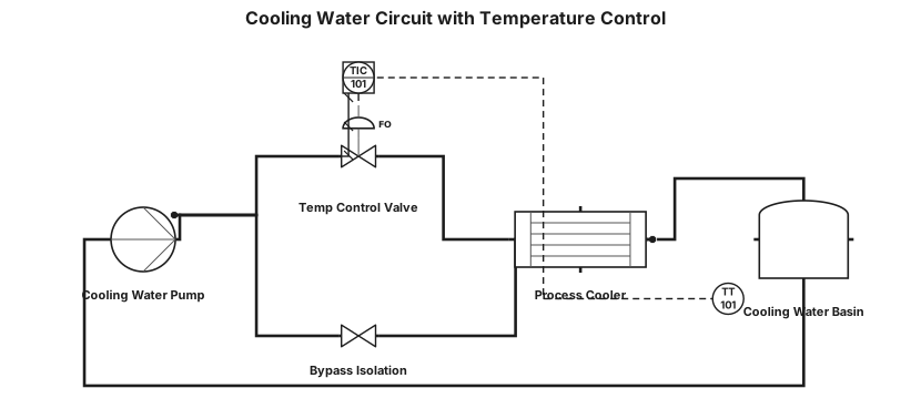
Cooling water circuit with temperature control valve and bypass
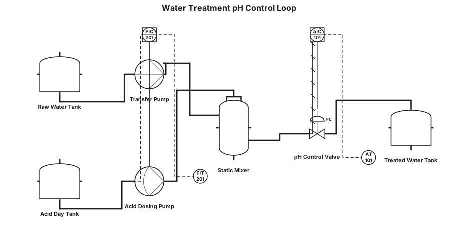
Water treatment loop with pH control and dosing pump
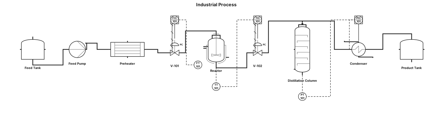
A P&ID for an industrial process
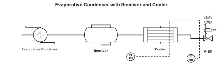
a evapourative condensor and it outlet is a receiver and it outlet is cooler put valve and PT and TT
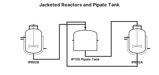
MAKE P&IF WHICH HAVE IPR02A AND IPR02B JACKATED REACTOR AND IPT05 PIPATE TANK AND LINE GOING IN IPR02A TO IPT05 AND IPR02B AND IPT05 LINE GO IN IPR02A
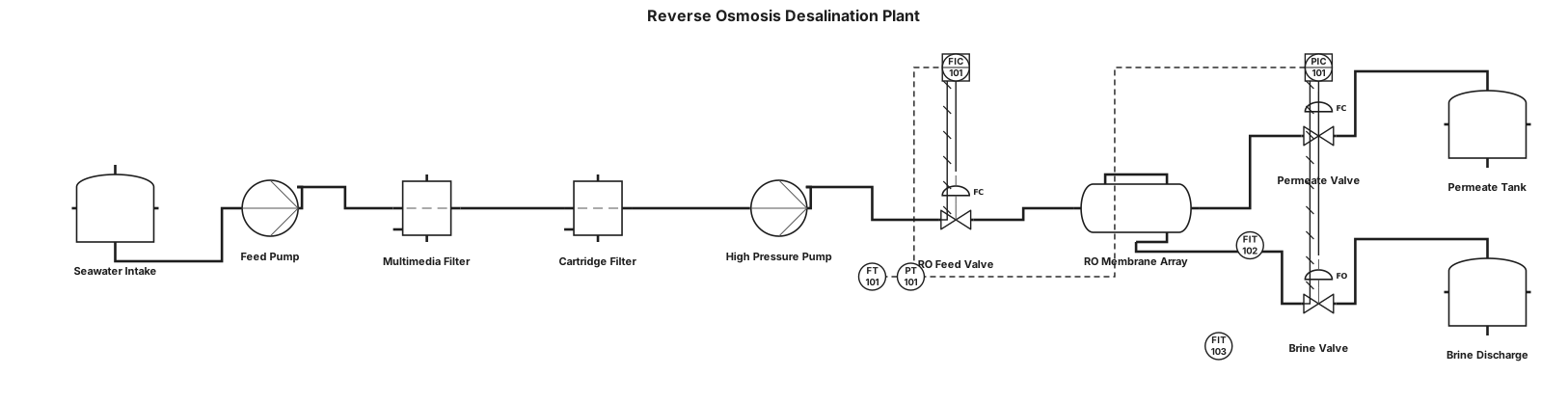
A P&ID for a reverse osmosis desalination plant
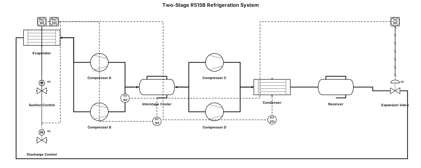
two stage refrigeration system for R515B with tandem scroll compressors and inter stage cooler vessel
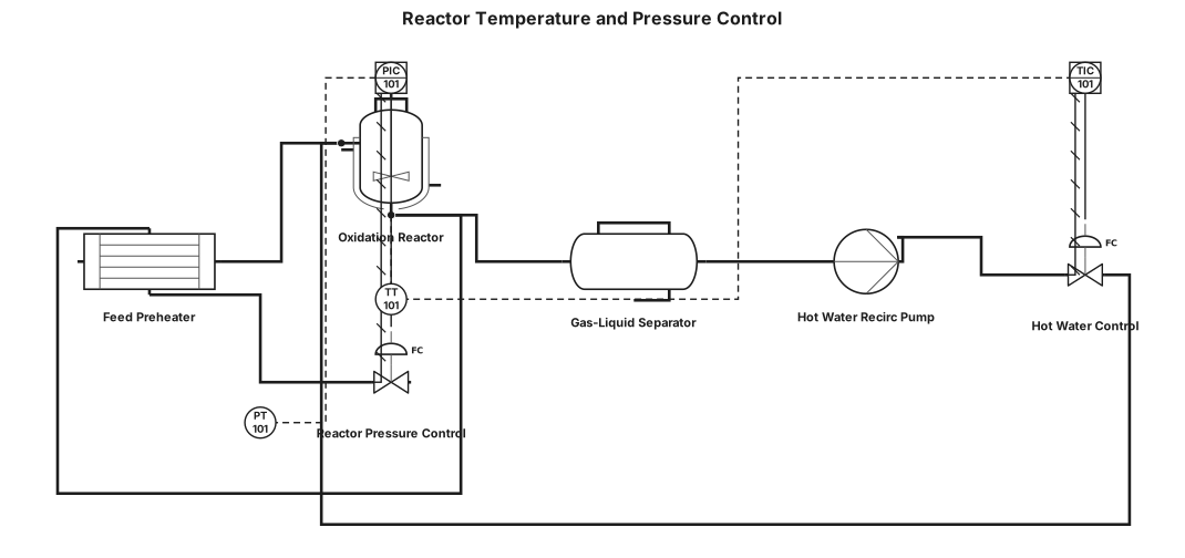
Feed gas is preheated in FP-01 using heat recovered from reactor effluent before entering reactor R-101. The oxidation reaction is highly exothermic, and heat is removed by circulating hot water through the shell side of the reactor. The heated water is separated into GLS-1 and recirculated by P-01. Reactor pressure is controlled through the effluent-side pressure control valve while reactor temperature is controlled through hot water circulation.
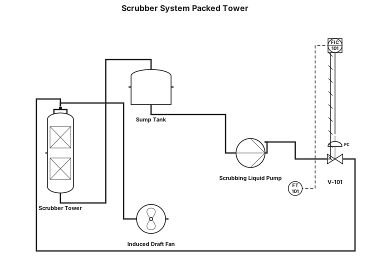
Scrubber system packed tower
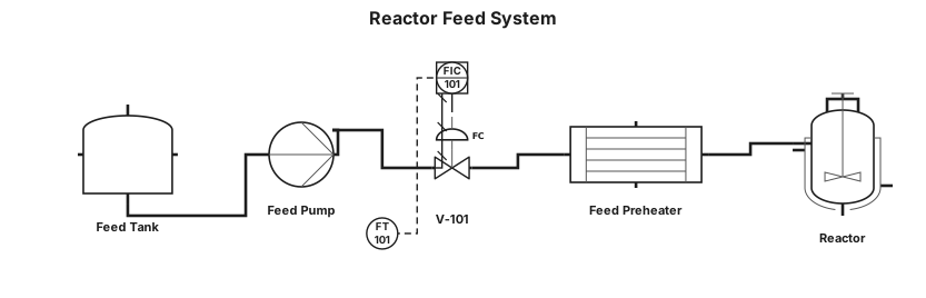
A P&ID for a chemical reactor feed system: feed tank, centrifugal pump, flow transmitter with a PID controller driving a control valve, and a heat exchanger before the reactor inlet
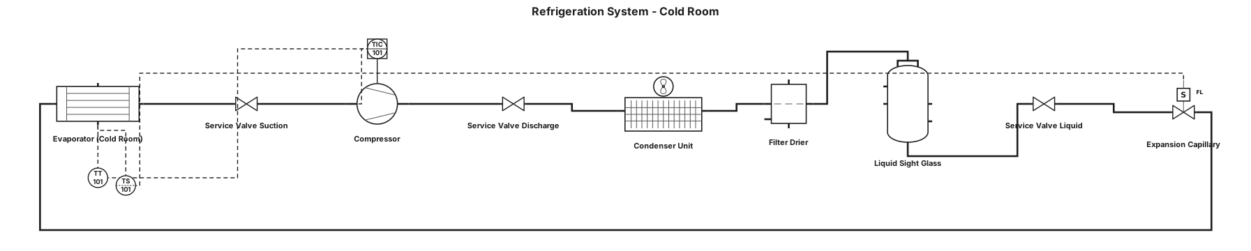
La instalación está formada por una unidad condensadora, un evaporador situado en el interior de la cámara, un compresor, un condensador, un filtro deshidratador, un visor de líquido, un capilar de expansión, un termostato y diferentes conexiones y válvulas de servicio. Todos estos componentes trabajan conjuntamente para permitir la circulación del refrigerante y la transferencia de calor.
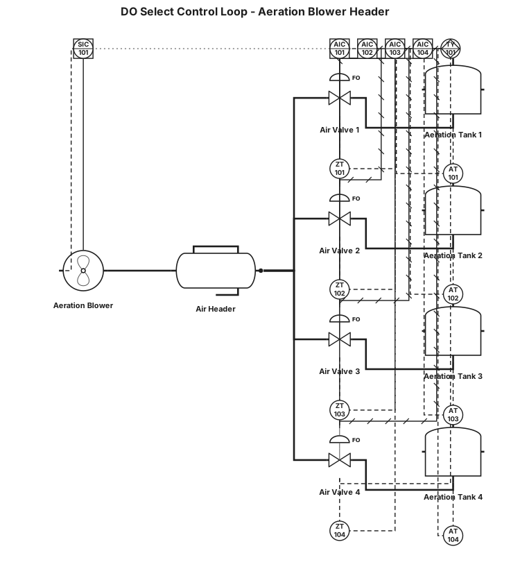
Here is the design for your Dissolved Oxygen (DO) Select Control Loop (often called a Most-Open-Valve or Valve-Position-Control strategy). This setup ensures that all four tanks get enough oxygen while running your blower at the lowest, most energy-efficient speed possible. 📋 Process Description 1. Each of the 4 tanks has its own DO Sensor and its own Modulating Air Valve. 2. Individual PID controllers modulate each valve to maintain the specific DO setpoint for that tank. 3. A High Selector (TY-01) continuously monitors the position (% open) of all 4 valves. 4. The highest valve position is passed to a Master Blower Controller. 5. If the most open valve is open too wide (e.g., >85%), the blower speeds up to provide more header pressure. If it is too closed (e.g., <75%), the blower slows down to save energy.
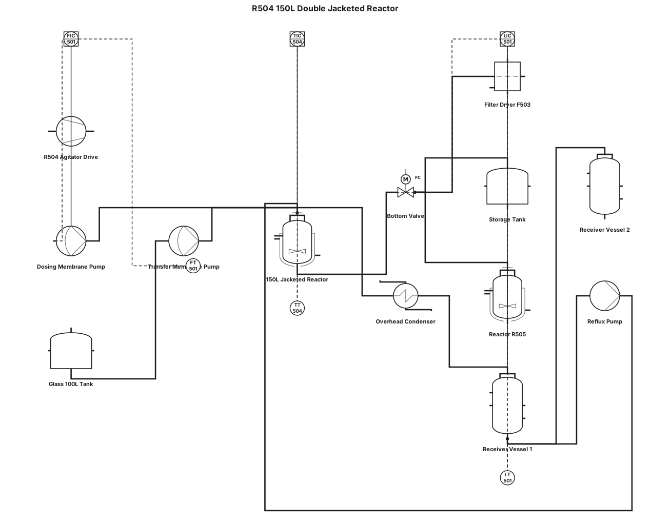
A P&ID for a chemical reactor : R504 150L double jacketed reactor with mixer; 1 bottom valve, 3 outlet possibilities (1 to filter dryer F503, 1 to storage tank and one to R505), 3 product entries one with dosing membrane pump, one trough a glass 100L tank and one trough a membrane pump, one condensing line with 2 receptors vessels for distillation and one reflux line.