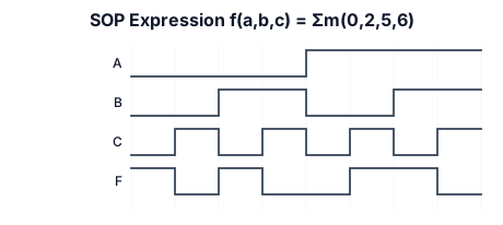
a timing diagram for sop expression f(a,b,c)=sigma m(0,2,5,6)
NODE ARCHIVE · REAL DIAGRAM BRIEFS
Diagram Examples from Real Visitor Prompts
Browse eligible diagrams shared by FreeDiagram visitors, inspect the exact prompts, and build your own version.
Browse 1014 real creationsCOMMUNITY OUTPUTS · EXACT PROMPTS
Timing Diagrams
Showing 1–24 of 26. No stock examples or system defaults. Choose a tool, study a real result, then reopen its prompt as your starting point.

A timing diagram for an I2C read transaction: \left(AB\right)+\left(\overline{B}c\right)
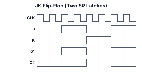
A timing diagram for an JK flip flop designed using two SR latches. show clk, J,K ,the output of the first latch, and the output of the second latch.
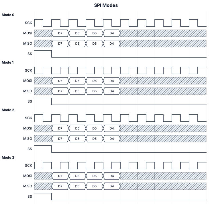
SPI with 4 modes, show time zero with vertical bar
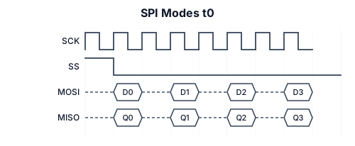
SPI with 4 modes, show t0
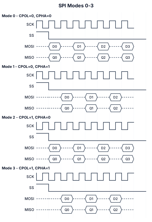
SPI with 4 modes
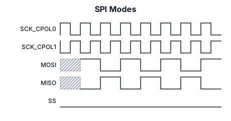
SPI Modes
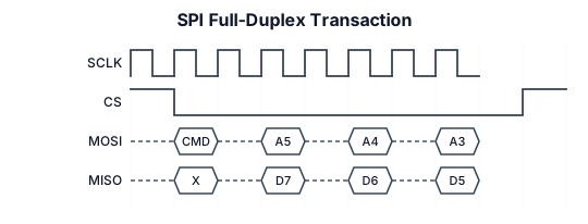
SPI full-duplex transaction with SCLK, MOSI, and MISO signals
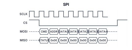
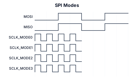
A timing diagram for an SPI Modes: (mosi/miso bit data), sclk (mode 0) cpol=0, cpha=0, sclk (mode 1) cpol=0, cpha=1, sclk (mode 3) cpol=1, cpha=0, sclk (mode 3) cpol=1, cpha=1
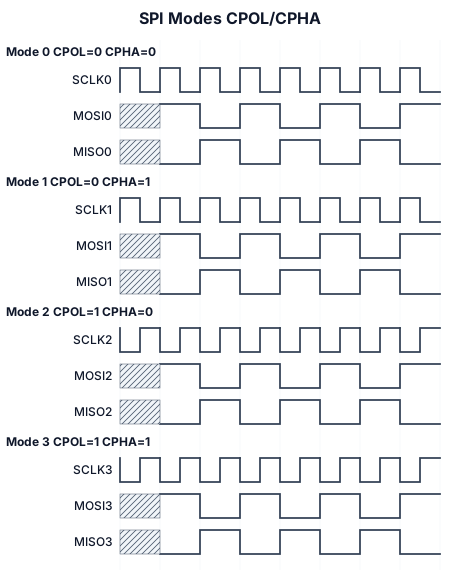
A timing diagram for an SPI Modes: (mosi/miso) (bit data), sclk (mode 0) cpol=0, cpha=0, sclk (mode 1) cpol=0, cpha=1, sclk (mode 3) cpol=1, cpha=0, sclk (mode 3) cpol=1, cpha=1
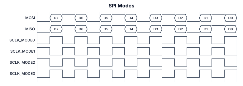
A timing diagram for an SPI Modes: mosi/miso(bit data), sclk (mode 0) cpol=0, cpha=0, sclk (mode 1) cpol=0, cpha=1, sclk (mode 3) cpol=1, cpha=0, sclk (mode 3) cpol=1, cpha=1
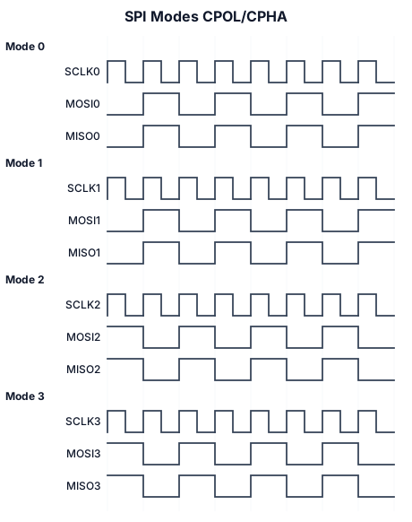
A timing diagram for an SPI Modes: mosi/miso data, sclk (mode 0) cpol=0, cpha=0, sclk (mode 1) cpol=0, cpha=1, sclk (mode 3) cpol=1, cpha=0, sclk (mode 3) cpol=1, cpha=1
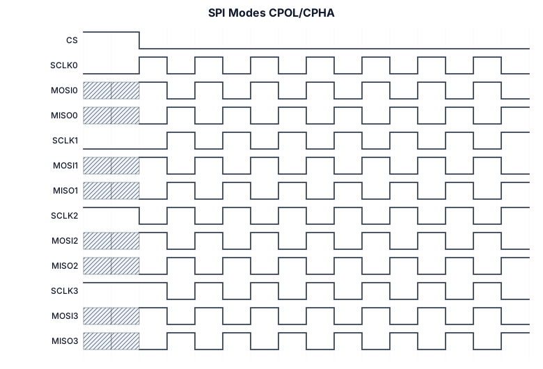
A timing diagram for an SPI Modes: mosi/miso, sclk (mode 0) cpol=0, cpha=0, sclk (mode 1) cpol=0, cpha=1, sclk (mode 3) cpol=1, cpha=0, sclk (mode 3) cpol=1, cpha=1
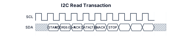
A timing diagram for an I2C read transaction: SCL clock, SDA with START condition, 7-bit address byte, ACK bit, data byte, and STOP condition
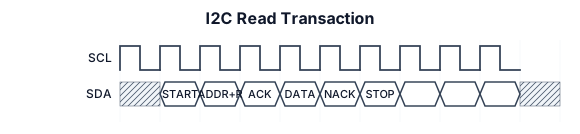
A timing diagram for an I2C read transaction: SCL clock, SDA with START condition, 7-bit address byte, ACK bit, data byte, and STOP condition
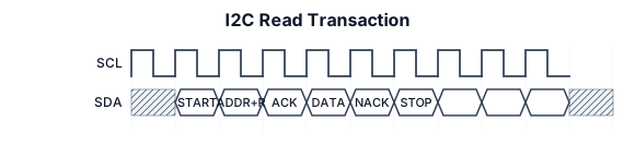
A timing diagram for an I2C read transaction: SCL clock, SDA with START condition, 7-bit address byte, ACK bit, data byte, and STOP condition

Start all signals at 0 besides LT03 A signal SV06 which and its timer SV06T which asserts after a 3 cycle delay if 51P or 51G1 asserts. Have 51P assert after 10 cycles for the duration of 20 cycles A signal SV05 and its dropout deay 3600 cycles, the dropout indicates that the signal SV05T will remain high as SV05 is high, if SV05 deasserts SV05T will dropout after 3600 cycles. The signal logic is R_TRIG SV06T AND (LT03 OR LT04) # TRIGGER FOR OVERCURRENT (RESET COUNTER WHEN TIMED OUT) SECTIONALIZER COUNT Provide LT03 signal as passivley active

A signal SV06 which and its timer SV06T which asserts after a 3 cycle delay if 51P or 51G1 asserts. Have 51P assert after 10 cycles for the duration of 20 cycles A signal SV05 and its dropout deay 3600 cycles, the dropout indicates that the signal SV05T will remain high as SV05 is high, if SV05 deasserts SV05T will dropout after 3600 cycles. The signal logic is R_TRIG SV06T AND (LT03 OR LT04) # TRIGGER FOR OVERCURRENT (RESET COUNTER WHEN TIMED OUT) SECTIONALIZER COUNT Provide LT03 signal as passivley active
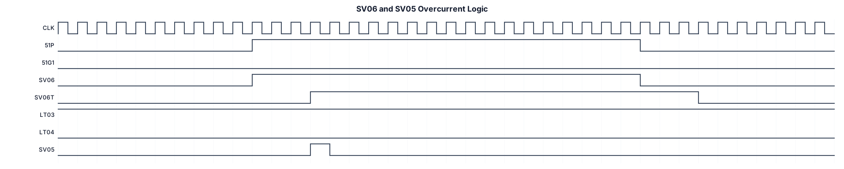
A signal SV06 which and its timer SV06T which asserts after a 3 cycle delay if 51P or 51G1 asserts. Have 51P assert after 10 cycles for the duration of 20 cycles A signal SV05 and its dropout deay 3600 cycles. The signal logic is R_TRIG SV06T AND (LT03 OR LT04) # TRIGGER FOR OVERCURRENT (RESET COUNTER WHEN TIMED OUT) SECTIONALIZER COUNT Provide LT03 signal as passivley active
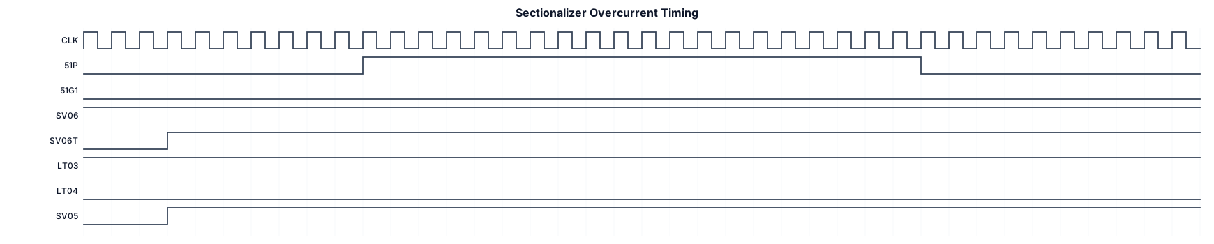
A signal SV06 which asserts immediately and its timer SV06T which asserts after a 3 cycle delay if 51P or 51G1 asserts. Have 51P assert after 10 cycles for the duration of 20 cycles A signal SV05 and its dropout deay 3600 cycles. The signal logic is R_TRIG SV06T AND (LT03 OR LT04) # TRIGGER FOR OVERCURRENT (RESET COUNTER WHEN TIMED OUT) SECTIONALIZER COUNT Provide LT03 signal as passivley active

A signal SV06 which asserts after a 3 cycle delay if 51P or 51G1 asserts. Have 51P assert after 10 cycles for the duration of 20 cycles

A signal SV06 which asserts if 51P or 51G1 asserts. Have 51P assert after 10 cycles for the duration of 20 cycles

A timing diagram for an I2C read transaction: SCL clock, SDA with START condition, 7-bit address byte, ACK bit, data byte, and STOP condition
Focused examples and prompt ideas
Start with the complete visitor wall above, then use these focused collections when you want a narrower subject and more prompt context.
The first curated collection is being prepared.