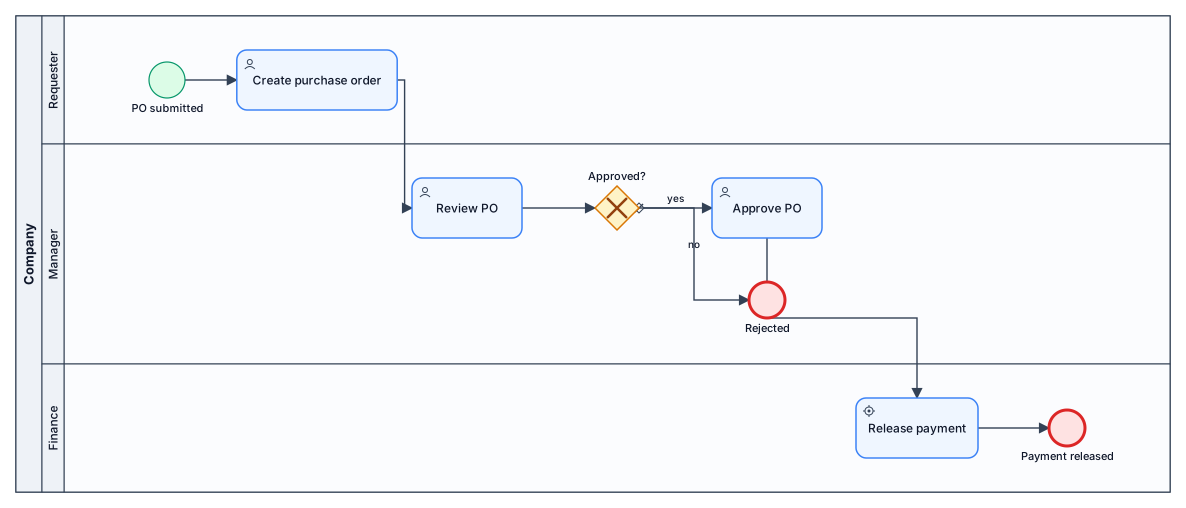
A BPMN diagram of a purchase-order approval process across three lanes: requester submits a PO, manager reviews and approves or rejects, finance releases payment
NODE ARCHIVE · REAL DIAGRAM BRIEFS
Diagram Examples from Real Visitor Prompts
Browse eligible diagrams shared by FreeDiagram visitors, inspect the exact prompts, and build your own version.
Browse 3327 real creationsCOMMUNITY OUTPUTS · EXACT PROMPTS
All visitor creations
Showing 2881–2904 of 3327. No stock examples or system defaults. Choose a tool, study a real result, then reopen its prompt as your starting point.
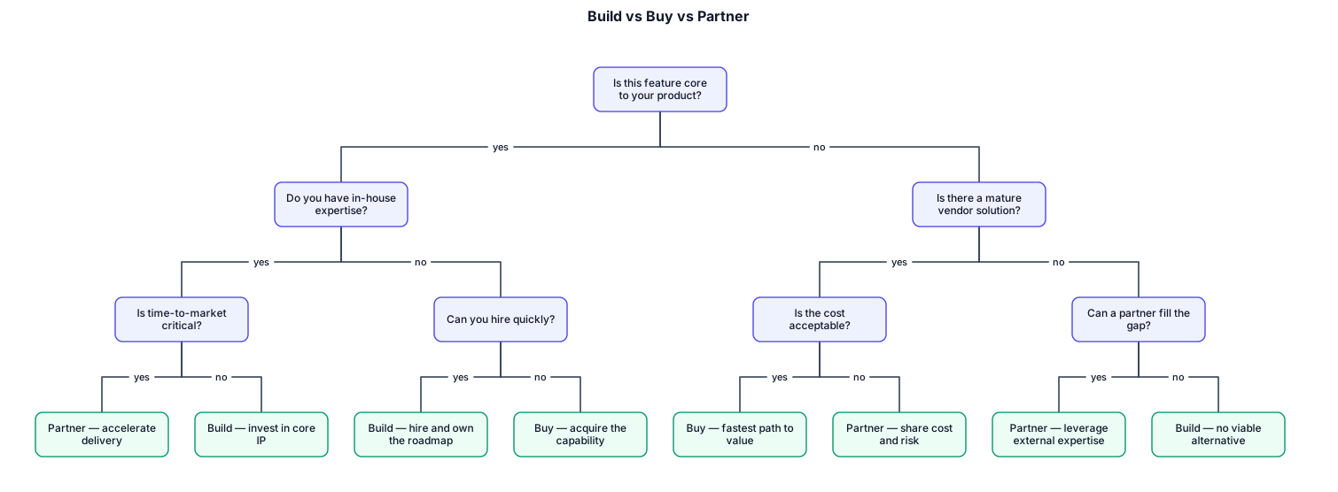
A decision tree for whether a startup should build, buy, or partner for a new feature
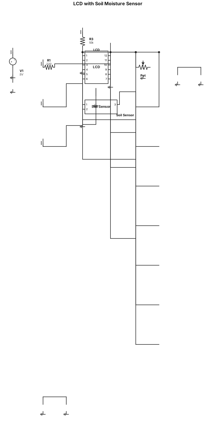
Create a circuit diagram with these exact connections: LCD: VSS → GND VDD → 5V VO → Potentiometer middle pin RS → D7 RW → GND E → D8 D4 → D9 D5 → D10 D6 → D11 D7 → D12 A/LED+ → 5V through 220Ω resistor K/LED− → GND Potentiometer: One end → GND Other end → 5V Middle pin → LCD VO Soil Moisture Sensor: VCC → 5V GND → GND SIG/AO → A0
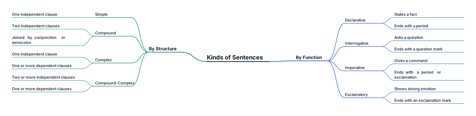
kinds of sentences

Senior Mechanical Engineer 1 Mechanical Engineer 0 Mech. Supervisor 1 Instrumentation Supervisor 1 Plant Operators 30 Water Feature Technician 3 Chemist / Lab Technician 1 Heavy Duty Pump Technician 2 Instrumentation Technician 2 HVAC Engineer 2 HVAC Supervisor 6 Senior AC Technician 12 Chiller Technician 18 HVAC Technician 75 Asst. AC Technician 40 Control Technician 4 Pump Technician 8 Duct Man / AC Technician 2 Insulator Technician 2 Sr. Electrical Engineer 1 Electrical Engineer 1 Electrical Supervisor (Power) 3 Electrical Supervisor (Low Current) 4 Electrical Technician (MV System) 6 Electrical Technician (LV System) 18 Generator Technician 2 Technician Power Control 2 Technician - ELV / Electronic 6 BMS Control Room Operator 5 LV / MV Cable Jointer 1 Substation Operator 21 Assistant Electrician 15 Driver 10 Coordinator 1 HSE Engineer 4

Senior Mechanical Engineer 11,000.00 1 Mechanical Engineer 8,000.00 0 Mech. Supervisor 3,000.00 1 Instrumentation Supervisor 3,000.00 1 Plant Operators 2,300.00 30 Water Feature Technician 1,750.00 3 Chemist / Lab Technician 2,500.00 1 Heavy Duty Pump Technician 2,000.00 2 Instrumentation Technician 2,000.00 2 HVAC Engineer 6,500.00 2 HVAC Supervisor 3,000.00 6 Senior AC Technician 2,500.00 12 Chiller Technician 3,500.00 18 HVAC Technician 1,750.00 75 Asst. AC Technician 1,000.00 40 Control Technician 2,400.00 4 Pump Technician 2,000.00 8 Duct Man / AC Technician 1,500.00 2 Insulator Technician 3,000.00 2 Sr. Electrical Engineer 10,000.00 1 Electrical Engineer 7,500.00 1 Electrical Supervisor (Power) 3,000.00 3 Electrical Supervisor (Low Current) 3,000.00 4 Electrical Technician (MV System) 2,000.00 6 Electrical Technician (LV System) 2,000.00 18 Generator Technician 2,000.00 2 Technician Power Control 2,500.00 2 Technician - ELV / Electronic 1,800.00 6 BMS Control Room Operator 3,000.00 5 LV / MV Cable Jointer 2,000.00 1 Substation Operator 2,000.00 21 Assistant Electrician 1,200.00 15 Driver 2,000.00 10 Coordinator 4,000.00 1 HSE Engineer 5,000.00 4
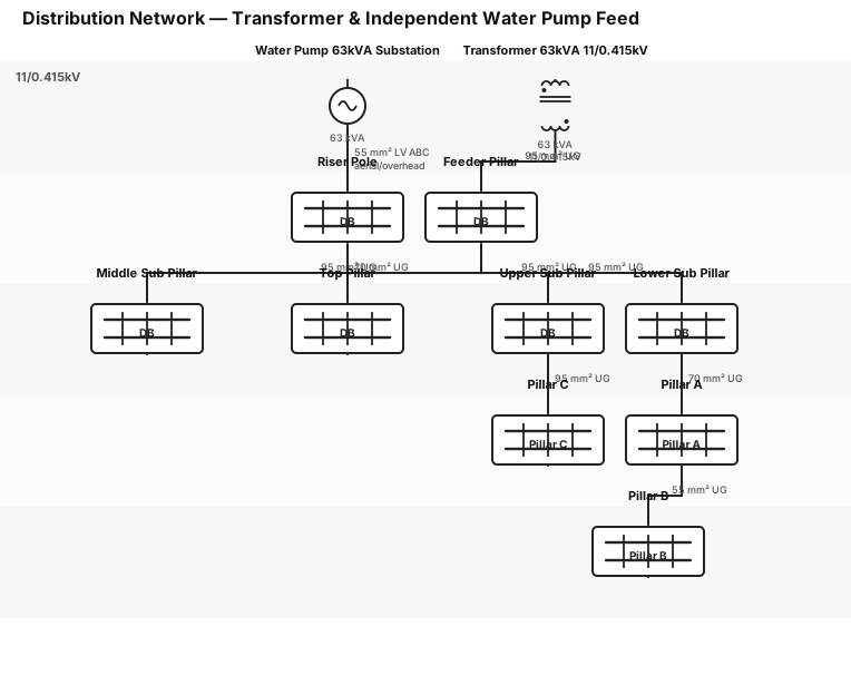
Create a single line diagram (SLD) for an electrical distribution system with the following components and connections, arranged top-to-bottom in a hierarchical layout: Transformer — 63kVA, 11/0.415kV (use standard 2-winding transformer symbol) Transformer connects to Feeder Pillar via 95sqmm UG cable Feeder Pillar has 3 outgoing feeds, all via 95sqmm UG cable, to: Lower Sub Pillar Middle Sub Pillar Upper Sub Pillar Lower Sub Pillar connects onward to Pillar A via 70sqmm UG cable Pillar A connects onward to Pillar B via 55sqmm UG cable Upper Sub Pillar connects onward to Pillar C via 95sqmm UG cable Middle Sub Pillar has no further downstream connection Separately, show a second independent feed (not connected to the transformer above): Water Pump 63kVA Substation (separate source) connects to a Riser Pole via LV ABC 55sqmm aerial cable (label this segment as aerial/overhead) Riser Pole connects to Top Pillar via 70sqmm UG cable (underground) Use standard electrical/panel symbols where available (transformer symbol, distribution panel/pillar boxes with bus bar lines, breaker marks at connection points). Label every cable segment with its size and type (UG = underground, LV ABC = aerial bunched cable). Visually separate the water pump/top pillar branch from the main transformer branch to show they are electrically independent systems on the same drawing.

I need a web chart with 5 pillars and description all in one page for my front desk team. In middle want Guest service experience and all the pillars connecting to it like a web. here is the info: PRESTIGE MOUNTAIN RESORT ROSSLAND GUEST EXPERIENCE FLOW NOTICE → ANTICIPATE → PERSONALIZE Observe Think Ahead Make It About Them ↓ ↓ ↓ ACT → FOLLOW UP Take Initiative Show You Care NOTICE • What do I observe? • What matters to this guest? • What have they told me about themselves? ANTICIPATE • What will they need next? • What questions can I answer before they ask? PERSONALIZE • Use names • Remember details • Tailor recommendations • Recognize special occasions ACT • Take ownership • Offer help • Prevent problems • Create memorable moments FOLLOW UP • Continue conversations • Ask about their plans • Follow up on previous discussions • Show you remembered
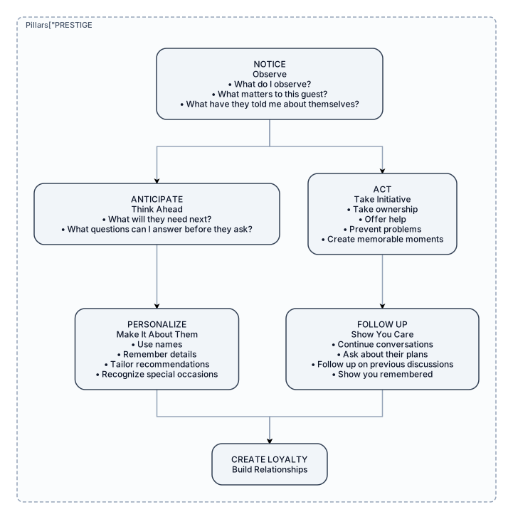
I need a web chart with 5 pillars and describtion all in one page for my front desk team here is the info: PRESTIGE MOUNTAIN RESORT ROSSLAND GUEST EXPERIENCE FLOW NOTICE → ANTICIPATE → PERSONALIZE Observe Think Ahead Make It About Them ↓ ↓ ↓ ACT → FOLLOW UP → CREATE LOYALTY Take Initiative Show You Care Build Relationships NOTICE • What do I observe? • What matters to this guest? • What have they told me about themselves? ANTICIPATE • What will they need next? • What questions can I answer before they ask? PERSONALIZE • Use names • Remember details • Tailor recommendations • Recognize special occasions ACT • Take ownership • Offer help • Prevent problems • Create memorable moments FOLLOW UP • Continue conversations • Ask about their plans • Follow up on previous discussions • Show you remembered

I need a web chart with 5 pillars and describtion all in one page for my front desk team here is the info: PRESTIGE MOUNTAIN RESORT ROSSLAND GUEST EXPERIENCE FLOW NOTICE → ANTICIPATE → PERSONALIZE Observe Think Ahead Make It About Them ↓ ↓ ↓ ACT → FOLLOW UP → CREATE LOYALTY Take Initiative Show You Care Build Relationships NOTICE • What do I observe? • What matters to this guest? • What have they told me about themselves? ANTICIPATE • What will they need next? • What questions can I answer before they ask? PERSONALIZE • Use names • Remember details • Tailor recommendations • Recognize special occasions ACT • Take ownership • Offer help • Prevent problems • Create memorable moments FOLLOW UP • Continue conversations • Ask about their plans • Follow up on previous discussions • Show you remembered ASK ↓ LISTEN ↓ LEARN WHAT MATTERS ↓ PERSONALIZE ↓ CREATE CONNECTION ↓ CREATE LOYALTY EVERY SHIFT Learn 1 Meaningful Thing Anticipate 1 Need Create 1 Memorable Moment Leave Every Guest Feeling: WELCOME • UNDERSTOOD • VALUED CARED FOR • CONFIDENT • APPRECIATED

An org chart for a 50-person tech company with engineering, product, design, sales, and ops
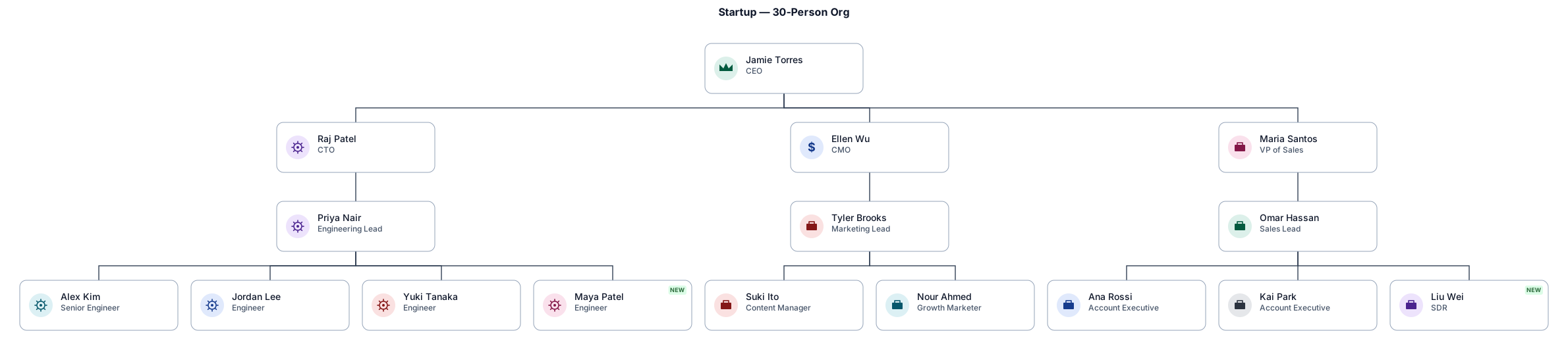
An org chart for a 30-person startup with a CEO, CTO, CMO, and VP of Sales at the top — then engineering, product, marketing, and sales teams below with their leads

Low-pressure exhaust steam from the turbine enters the direct-contact condenser HE-201, where it is condensed by intimate contact with circulating cooling water; the non-condensable gases (NCGs) collect at the top of HE-201 and are routed via stream 5 to reinjection, while the condensed steam mixed with cooling water ("brine") collects at the bottom of HE-201 and is pumped by P-202 via stream 6 to preheating. The cooling water side is served by cooling tower CT-201, which receives warm cooling water return from the condensing loop plus fresh makeup water (cooling water supply); cooled water collects in the CT-201 basin and is pumped by P-201 via stream 8 back up to HE-201 to sustain the direct-contact condensing duty, closing the loop with return stream 7 feeding into CT-201. Blowdown is taken from the cooling water circuit near CT-201/P-201 via stream 9 to reinjection to control dissolved solids buildup, and a second cooling water supply take-off exits the circuit to an off-page user. Key equipment: HE-201 (direct-contact condenser, vertical vessel), CT-201 (cooling tower), P-201 (cooling water circulation pump, CT-201→HE-201), P-202 (brine/condensate pump, HE-201→preheating); for the P&ID, add line numbers and pipe specs on all segments, isolation valves at every equipment nozzle, check valves on both pump discharges, level control (LT/LC) on the HE-201 hotwell driving P-202 and the brine control valve, conductivity-based blowdown control (AT/valve) on stream 9, basin level/makeup control on CT-201, pressure/temperature instrumentation (PT/TT) on the exhaust steam line and HE-201, and sheet-number references on all off-page connectors (turbine, NCG reinjection, preheating, cooling water supply/source, blowdown reinjection).
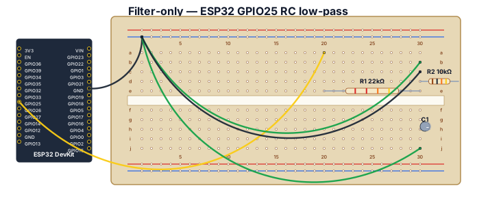
Create a FILTER-ONLY Fritzing-style breadboard close-up. Show one generic ESP32 DevKit on the left and one breadboard. Do NOT include the potentiometer or LCD. Exact placement and wiring: connect ESP32 GND to the breadboard blue ground rail. Connect ESP32 GPIO25 with a yellow jumper to breadboard row 20 on the a-e side. Place R1, 22 kOhm, from row 20 to row 30 on the a-e side, so it is in series with GPIO25. Row 30 is the OUT node. Place R2, 10 kOhm, from row 30 to the blue GND rail. Place C1, polarized electrolytic 10 uF, from row 30 to the blue GND rail, with its positive (+) lead in row 30 and negative (-) lead in the GND rail. Add a clearly labeled green OUT / DUT SIGNAL jumper from row 30. Add DUT GND to the blue ground rail. Use labels GPIO25 PWM, R1 22k, OUT, R2 10k, C1 10uF, capacitor + and -, DUT SIGNAL, DUT GND. Include a red warning label: NEVER CONNECT DUT DIRECTLY TO GPIO25. Ensure every connection follows breadboard row connectivity and do not add any other components or wires.
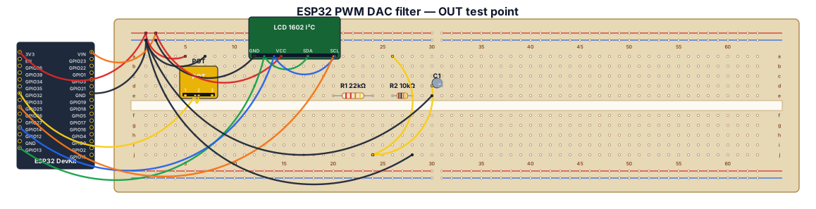
Create a clear Fritzing-style breadboard wiring diagram for a Freenove ESP32 WROVER CAM board (a generic ESP32 DevKit representation is acceptable), a 10k potentiometer, an I2C LCD1602, two resistors, and one polarized electrolytic capacitor. Exact connections: potentiometer outer pins to ESP32 3.3V and GND, center wiper to GPIO32. LCD1602 GND to GND, VCC to 5V, SDA to GPIO13, SCL to GPIO14. Filtered PWM output: GPIO25 connects ONLY to one end of R1 22k ohm; the other end of R1 is the OUT node. From the OUT node connect R2 10k ohm to GND. Also connect C1 10uF electrolytic from OUT to GND, with capacitor positive (+) at OUT and negative (-) at GND. Label OUT as the DUT analog input/test point and connect DUT ground to the common GND rail. Clearly show a common ground rail, resistor values, capacitor polarity, GPIO labels, and emphasize that the DUT must connect to OUT after R1, never directly to GPIO25.
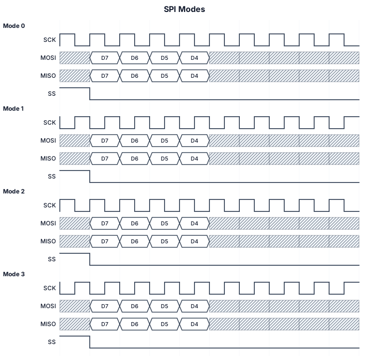
SPI with 4 modes, show time zero with vertical bar
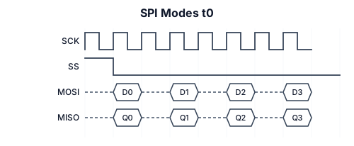
SPI with 4 modes, show t0
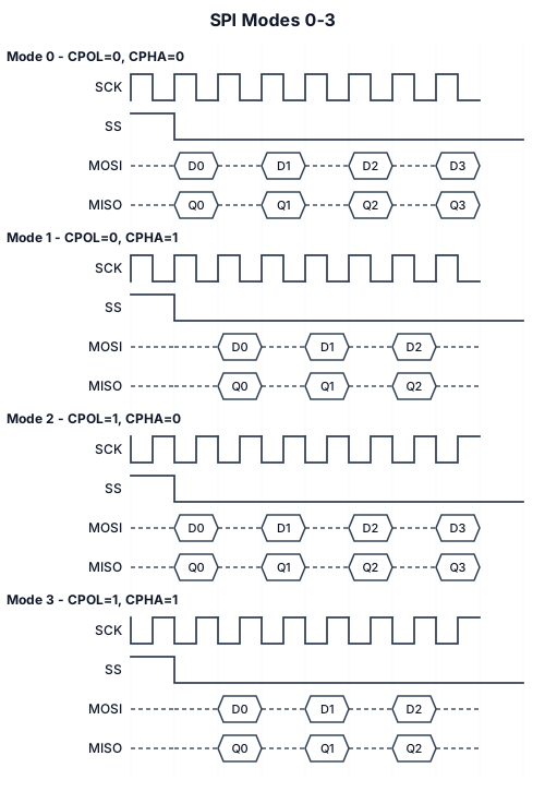
SPI with 4 modes
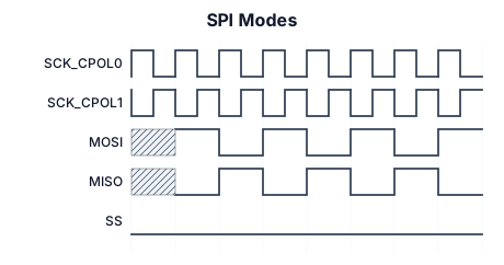
SPI Modes
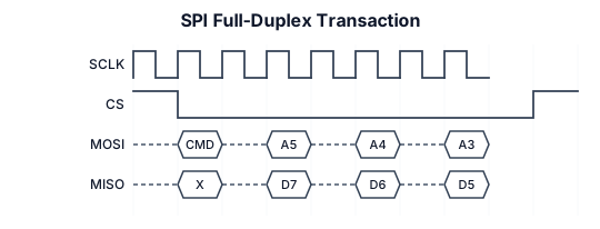
SPI full-duplex transaction with SCLK, MOSI, and MISO signals
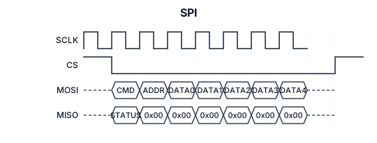
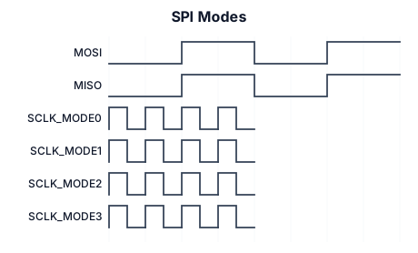
A timing diagram for an SPI Modes: (mosi/miso bit data), sclk (mode 0) cpol=0, cpha=0, sclk (mode 1) cpol=0, cpha=1, sclk (mode 3) cpol=1, cpha=0, sclk (mode 3) cpol=1, cpha=1
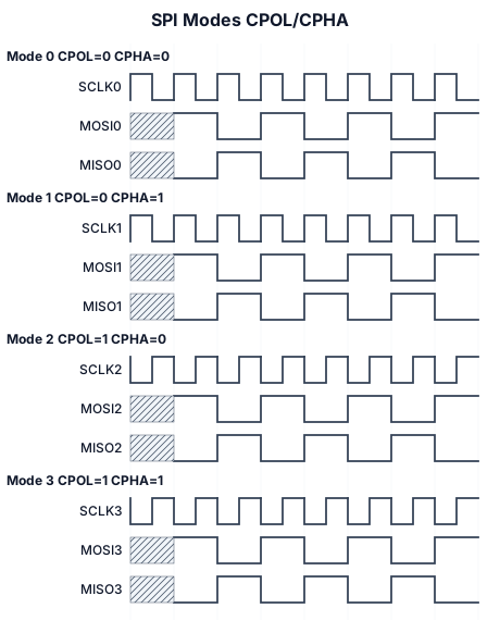
A timing diagram for an SPI Modes: (mosi/miso) (bit data), sclk (mode 0) cpol=0, cpha=0, sclk (mode 1) cpol=0, cpha=1, sclk (mode 3) cpol=1, cpha=0, sclk (mode 3) cpol=1, cpha=1
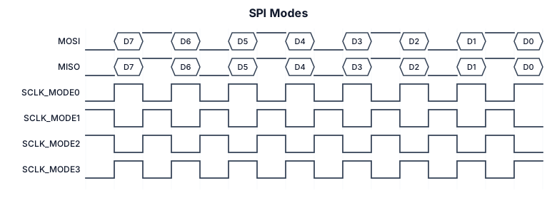
A timing diagram for an SPI Modes: mosi/miso(bit data), sclk (mode 0) cpol=0, cpha=0, sclk (mode 1) cpol=0, cpha=1, sclk (mode 3) cpol=1, cpha=0, sclk (mode 3) cpol=1, cpha=1