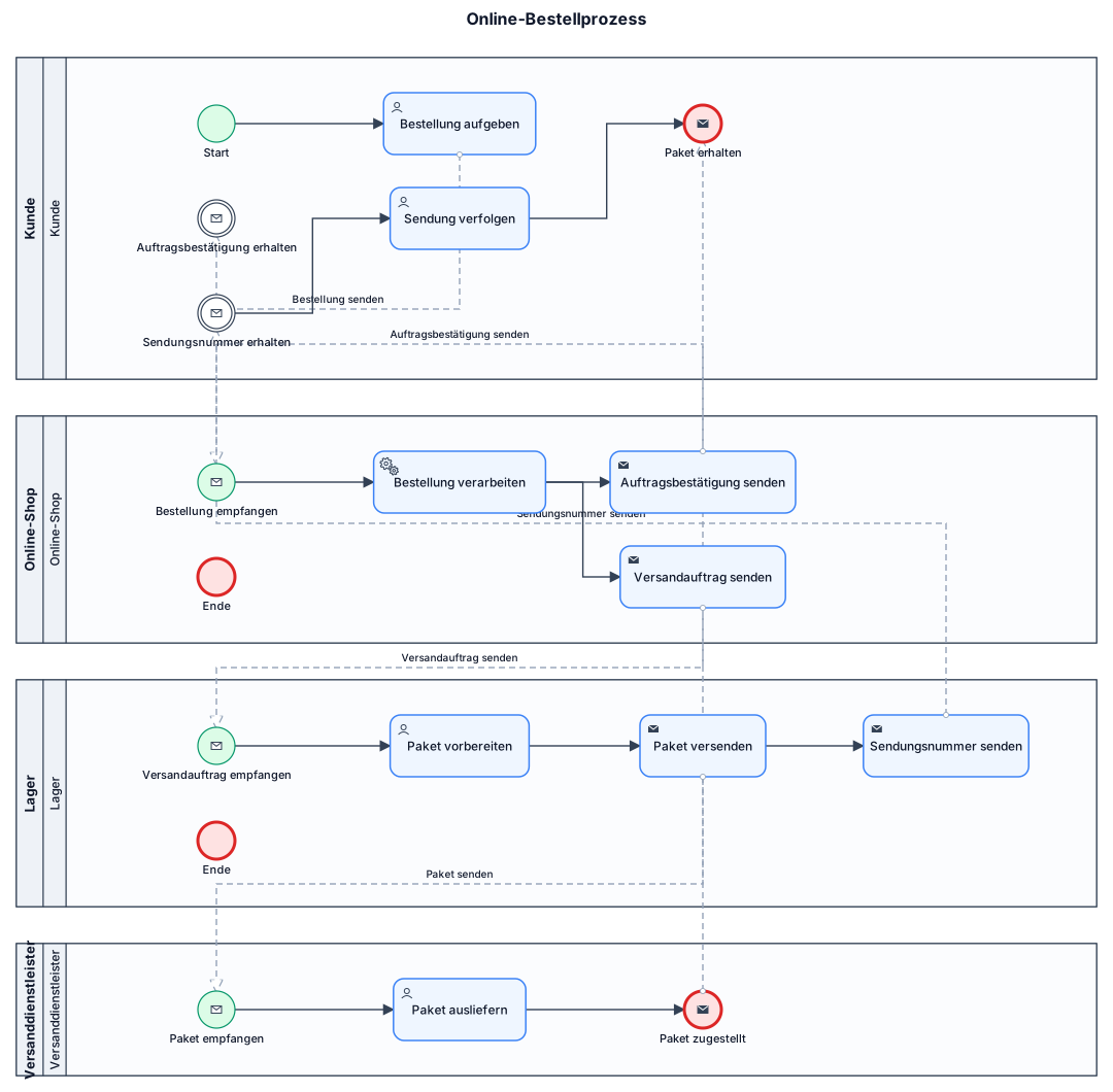
Please correct the existing BPMN 2.0 diagram without deleting the four participants. Fix the following problems: 1. The customer initiates the process. Use a normal start event followed by the task “Bestellung aufgeben”. 2. The online shop receives the order and sends an order confirmation to the customer. 3. The warehouse must receive the shipping order BEFORE preparing and shipping the package. 4. The customer receives the tracking number only after the shipment has been prepared for dispatch. 5. The shipping provider receives the package before delivering it. 6. The customer tracks the shipment and finally receives the package. Use proper BPMN 2.0 semantics: * Separate pools for independent participants. * Sequence flows within pools. * Message flows between pools. * Correct start and end events. * No duplicate or contradictory events. Make sure all activities and connections are visible and logically consistent.
Diagram Examples from Real Visitor Prompts
Browse eligible diagrams shared by FreeDiagram visitors, inspect the exact prompts, and build your own version.
Browse 3267 real creationsAll visitor creations
Showing 361–384 of 3267. No stock examples or system defaults. Choose a tool, study a real result, then reopen its prompt as your starting point.
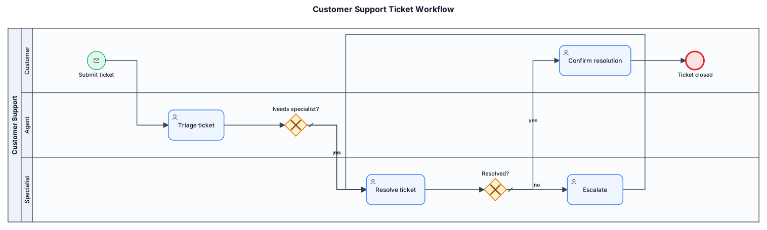
A BPMN diagram of a customer support ticket workflow: customer submits ticket, agent triages, specialist resolves or escalates, customer confirms resolution
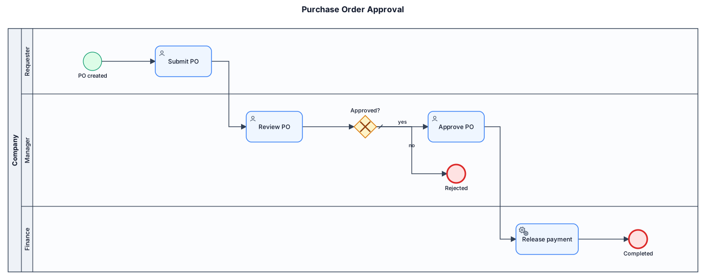
A BPMN diagram of a purchase-order approval process across three lanes: requester submits a PO, manager reviews and approves or rejects, finance releases payment
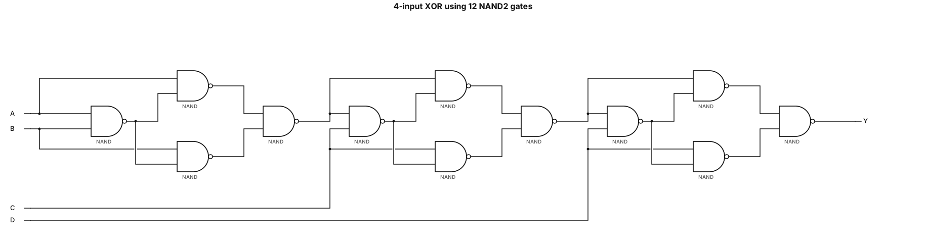
Draw a 4-input XOR logic circuit using ONLY 2-input NAND gates. Boolean function: Y = A XOR B XOR C XOR D STRICT REQUIREMENTS: - Use exactly 12 NAND2 gates. - Only inputs A, B, C, D are available. - No complementary inputs. - Do NOT use XOR, XNOR, AND, OR, NOT, or NAND3 gates. - Do NOT simplify or change the gate structure. Use these exact connections: Stage 1: N1 = NAND(A, B) N2 = NAND(A, N1) N3 = NAND(B, N1) X1 = NAND(N2, N3) Stage 2: N4 = NAND(X1, C) N5 = NAND(X1, N4) N6 = NAND(C, N4) X2 = NAND(N5, N6) Stage 3: N7 = NAND(X2, D) N8 = NAND(X2, N7) N9 = NAND(D, N7) Y = NAND(N8, N9) Draw all 12 NAND2 gates with labeled wires and inputs, from left to right. Total NAND2 gates = 12. Each NAND2 has 2 NMOS. Total NMOS = 24.
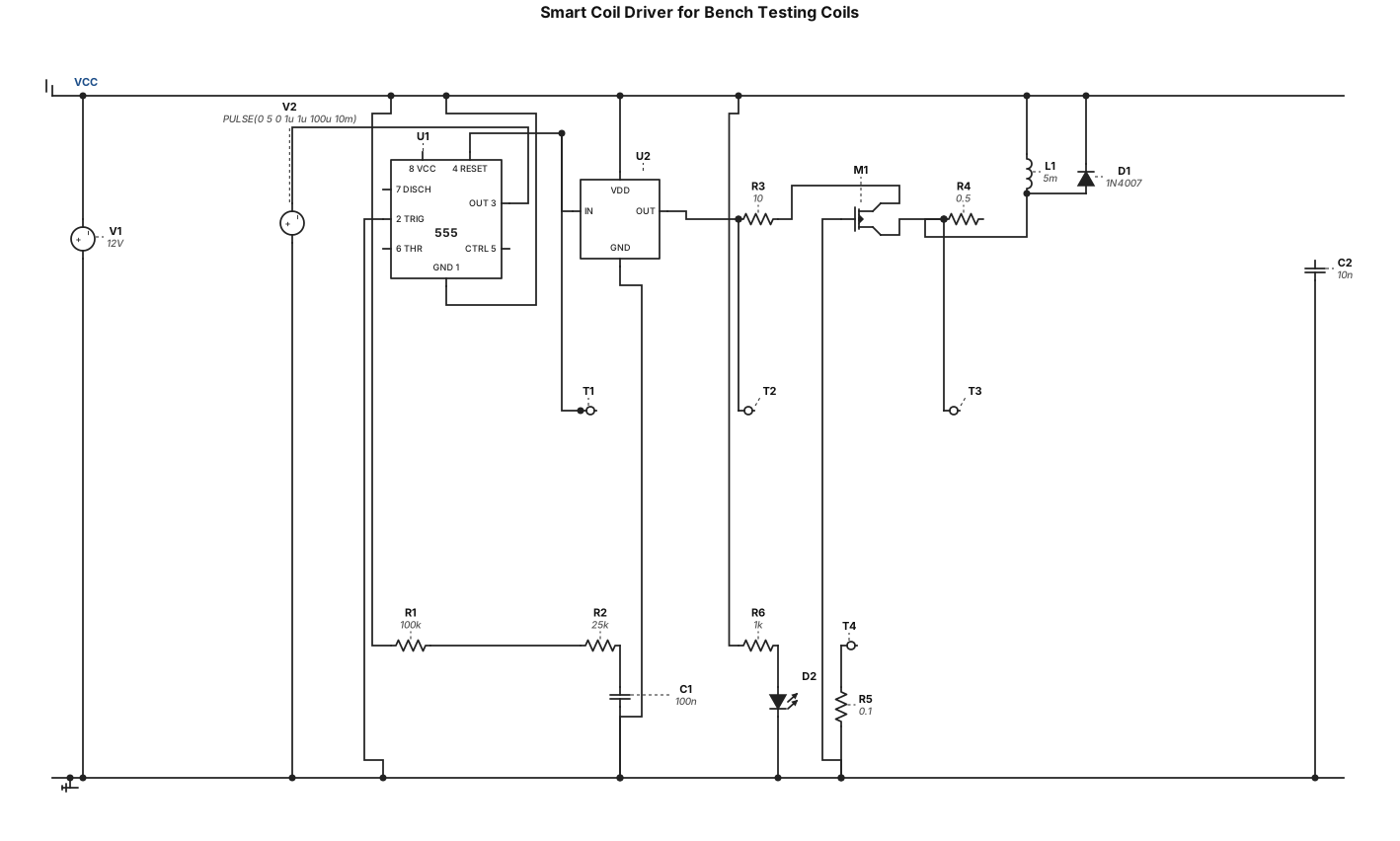
design a smart coil driver to bench test coils 2.5ms dwell . no arduino
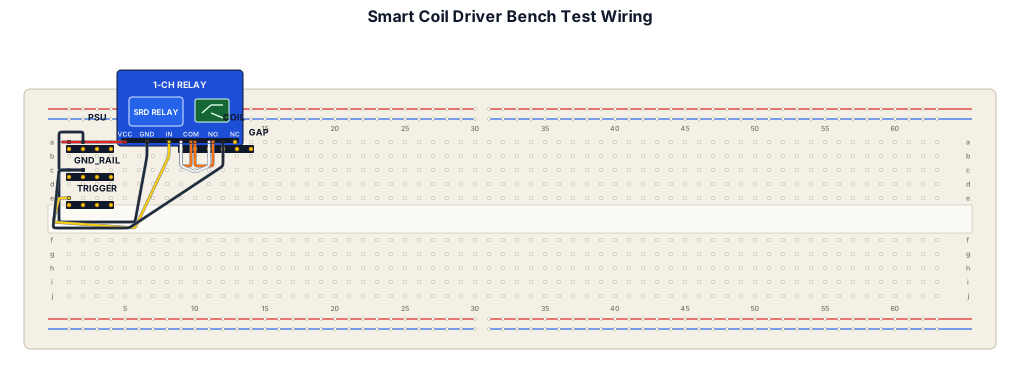
draw a wiring diagram for a smart coil driver to bench test coils

Директор, Маркетолог, Специалист по закупкам, Заведующий складом, Промышленный дизайнер, Инженер-конструктор, Специалист по электронике, Специалист по сертификации, Технолог, Оператор ТПА (термопластавтомата), Монтажник РЭА (радиоэлектронной аппаратуры), Сборщик прототипов / Сборщик-комплектовщик, Контролер ОТК, Юрист, Бухгалтер. Сделай диаграмму где важные професии верху, идут в низ к неважным
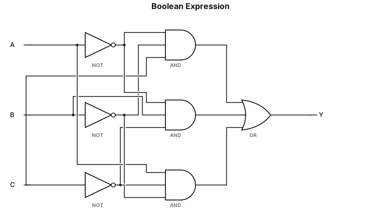
Y = (!A & !B & C) | (!A & B & !C) | (A & !B & !C)
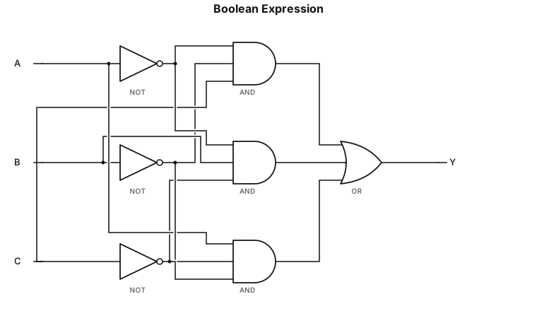
Y = Ā B̄ C + Ā B C̄ + A B̄ C̄
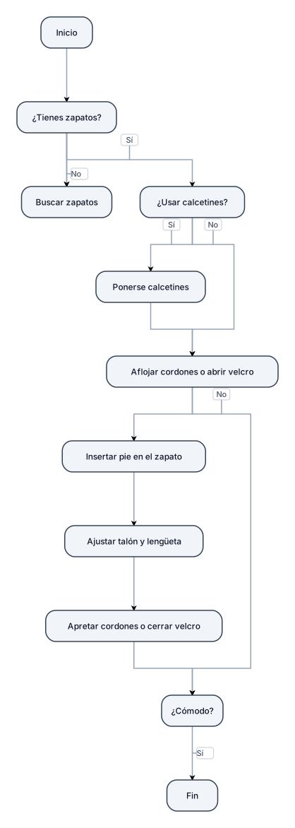
hazme un diagrama de flujo de como ponerse zapatos
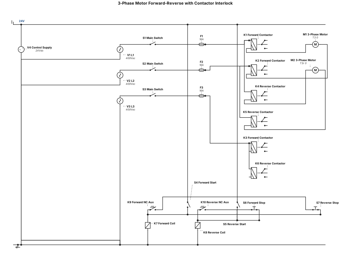
general main switch 3 phase with contactor for forward and contactor for backward with nc auxillary for protection each contactor working it.
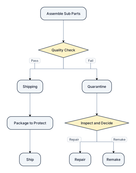
Assemble Sub parts move to Quaility, pass move to shipping, fail move to Quarantine at shipping package to protect and ship in quarantine inspect and decide to repair or remake

Assemble parts, move to QC, pass move to shipping fail more to quarantine
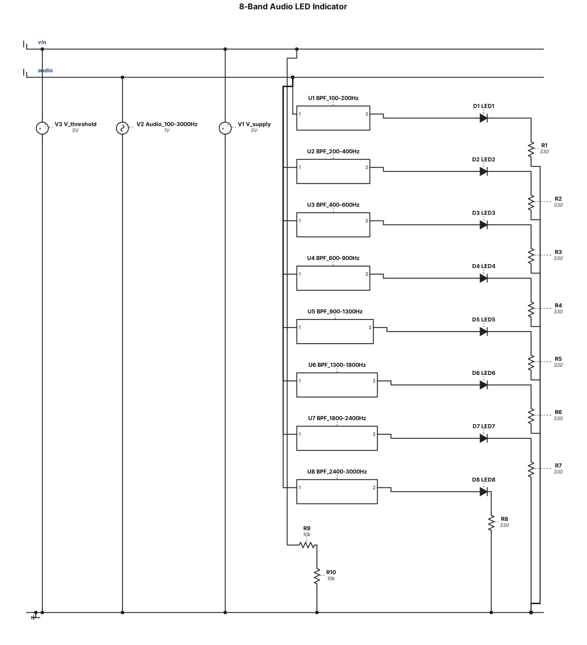
Voltage supply 5 V. Input signal is an audiosignal 100 to 3000 Hz. This signal should be split in 8 frequency bands and a led should indicate if the the frequencys in this band contribute to the whole signal (compared to a treshold), in a 1/0 setting: the output should be one (led full on) when strenght of signal in band is over treshold, otherwise output should be 0. Use as few components as possible.
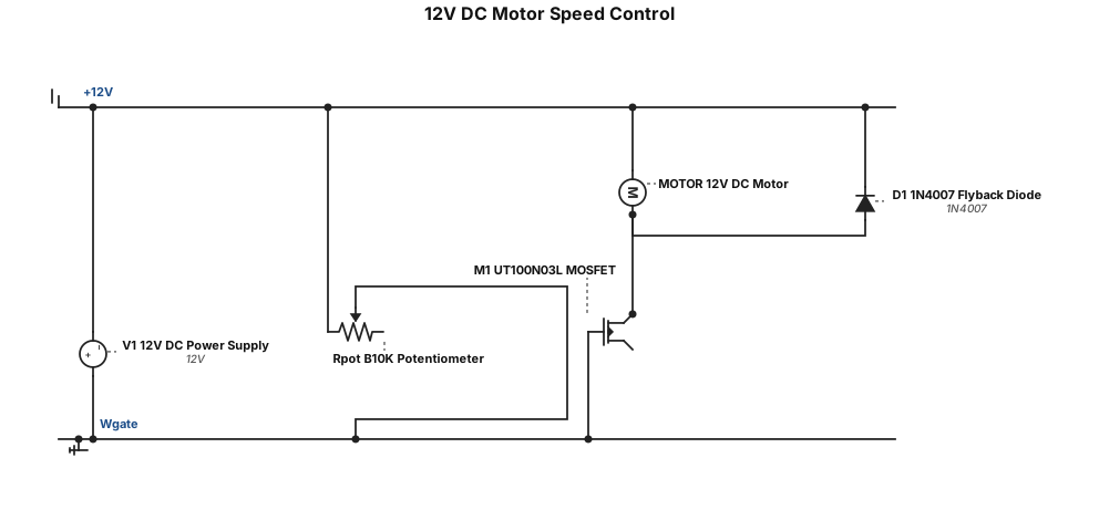
Generate a clean, structured schematic diagram for a 12V DC Motor Speed Control Circuit using an N-channel MOSFET. Components to include and label: 1. "12V DC Power Supply" (+12V and GND) 2. "B10K Potentiometer" (Pins: 1 = Left/GND, 2 = Wiper/Output, 3 = Right/+12V) 3. "UT100N03L MOSFET" (Pins labeled clearly: G = Gate, D = Drain, S = Source) 4. "12V DC Motor" (Terminals: Positive and Negative) 5. "1N4007 Flyback Diode" (Protection across the motor) Wiring Connections to map out: - Connect the 12V Power Supply Positive (+12V) to Pin 3 of the B10K Potentiometer and to the Positive terminal of the 12V DC Motor. - Connect the 12V Power Supply Negative (GND) to Pin 1 of the B10K Potentiometer and to the Source (S) pin of the UT100N03L MOSFET. - Connect Pin 2 (Wiper) of the B10K Potentiometer directly to the Gate (G) pin of the UT100N03L MOSFET. - Connect the Negative terminal of the 12V DC Motor to the Drain (D) pin of the UT100N03L MOSFET. - Place the 1N4007 Flyback Diode in parallel across the 12V DC Motor terminals, with the Cathode (striped side) connected to the motor's positive terminal and the Anode connected to the motor's negative terminal. Layout Orientation: Arrange left-to-right starting with the 12V Power Supply, moving to the Potentiometer, then the UT100N03L MOSFET, and placing the Motor at the top right. Use standard electrical engineering symbols for clarity.
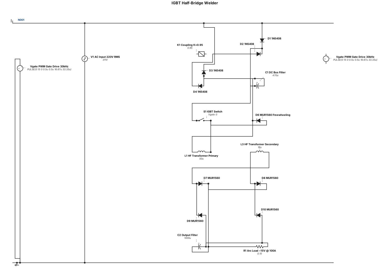
* === 1-IGBT HALF-BRIDGE WELDER === * Simpan sebagai: welder.cir → buka di LTspice → F9 * AC Input 220V RMS V1 N001 0 AC 311 * Bridge Rectifier D1 N001 VBUS+ D=1N5408 D2 N002 VBUS+ D=1N5408 D3 VBUS- N001 D=1N5408 D4 VBUS- N002 D=1N5408 * DC Bus Filter C1 VBUS+ VBUS- 470u * IGBT (switch model) S1 VBUS+ PHASE Vgate 0 SWIGBT * Freewheeling Diode D6 PHASE VBUS- D=MUR1560 * HF Transformer (coupled inductors, ratio 5:3) L1 PHASE VBUS- 50uH L3 N003 N004 18uH K1 L1 L3 0.95 * Secondary Bridge Rectifier D7 N003 OUT+ D=MUR1560 D8 N004 OUT+ D=MUR1560 D9 OUT- N003 D=MUR1560 D10 OUT- N004 D=MUR1560 * Output Filter C2 OUT+ OUT- 1000u * Arc Load (~15V @ 100A) R1 OUT+ OUT- 0.15 * Gate Drive: PWM 30kHz, 50% duty Vgate GND PULSE(0 15 0 0.5u 0.5u 16.67u 33.33u) * IGBT Model .MODEL SWIGBT SW(Ron=0.005 Roff=1e9 Vt=0 Voff=0) * Transient: 2ms, step 10ns .TRAN 0 2m 0 10u .END
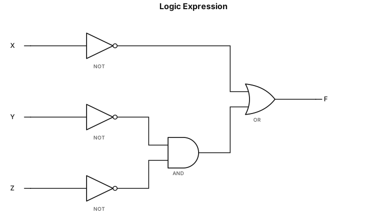
X'+Y'Z'
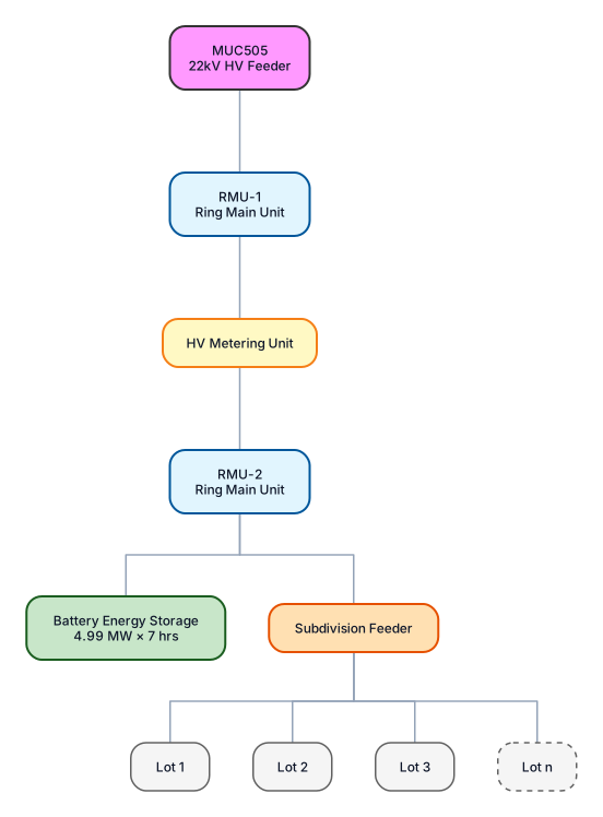
I want to draw a high level electrical SLD based on following: HV feeder MUC505 22kV Coming of this is an RMU which then connected back into the feeder. This RMU is to support an light industrial subdivision and the subdivision load is to be metered so associated with the RMU will be a HV metering unit. Out of this will be another separate RMU which will then have two load connections, 1 going to a capacity battery 4.99MW x 7hrs. The other load connection will be a feeder that suppliers the individual lots. The lot connections do not need to be shown in detail they can just be shown as branches. Show say 1 to 3 lots as an example and then draw such that implies it continues beyond 3 lots (ie. like 1, 2, 3 etc. etc. but in drawing terms). MUC needs to be a line and with two branches then feeding first RMU and HV meter before going into next RMU which then branches to capacity battery load and feeder supplying a number of subdivision lot loads with the lot loads shown as branches of that. Instead of trying to do as an SLD do as a flow chart instead. That looks good. Use same hiearchy but make it look a little more like an SLD by using some typical electrical symbols
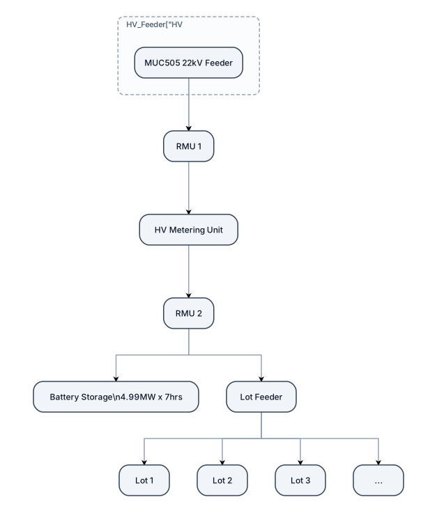
I want to draw a high level electrical SLD based on following: HV feeder MUC505 22kV Coming of this is an RMU which then connected back into the feeder. This RMU is to support an light industrial subdivision and the subdivision load is to be metered so associated with the RMU will be a HV metering unit. Out of this will be another separate RMU which will then have two load connections, 1 going to a capacity battery 4.99MW x 7hrs. The other load connection will be a feeder that suppliers the individual lots. The lot connections do not need to be shown in detail they can just be shown as branches. Show say 1 to 3 lots as an example and then draw such that implies it continues beyond 3 lots (ie. like 1, 2, 3 etc. etc. but in drawing terms). MUC needs to be a line and with two branches then feeding first RMU and HV meter before going into next RMU which then branches to capacity battery load and feeder supplying a number of subdivision lot loads with the lot loads shown as branches of that. Instead of trying to do as an SLD do as a flow chart instead

I want to draw a high level electrical SLD based on following: HV feeder MUC505 22kV Coming of this is an RMU which then connected back into the feeder. This RMU is to support an light industrial subdivision and the subdivision load is to be metered so associated with the RMU will be a HV metering unit. Out of this will be another separate RMU which will then have two load connections, 1 going to a capacity battery 4.99MW x 7hrs. The other load connection will be a feeder that suppliers the individual lots. The lot connections do not need to be shown in detail they can just be shown as branches. Show say 1 to 3 lots as an example and then draw such that implies it continues beyond 3 lots (ie. like 1, 2, 3 etc. etc. but in drawing terms). MUC needs to be a line and with two branches then feeding first RMU and HV meter before going into next RMU which then branches to capacity battery load and feeder supplying a number of subdivision lot loads with the lot loads shown as branches of that

I want to draw a high level electrical SLD based on following: HV feeder MUC505 22kV Coming of this is an RMU which then connected back into the feeder. This RMU is to support an light industrial subdivision and the subdivision load is to be metered so associated with the RMU will be a HV metering unit. Out of this will be another separate RMU which will then have two load connections, 1 going to a capacity battery 4.99MW x 7hrs. The other load connection will be a feeder that suppliers the individual lots. The lot connections do not need to be shown in detail they can just be shown as branches. Show say 1 to 3 lots as an example and then draw such that implies it continues beyond 3 lots (ie. like 1, 2, 3 etc. etc. but in drawing terms).
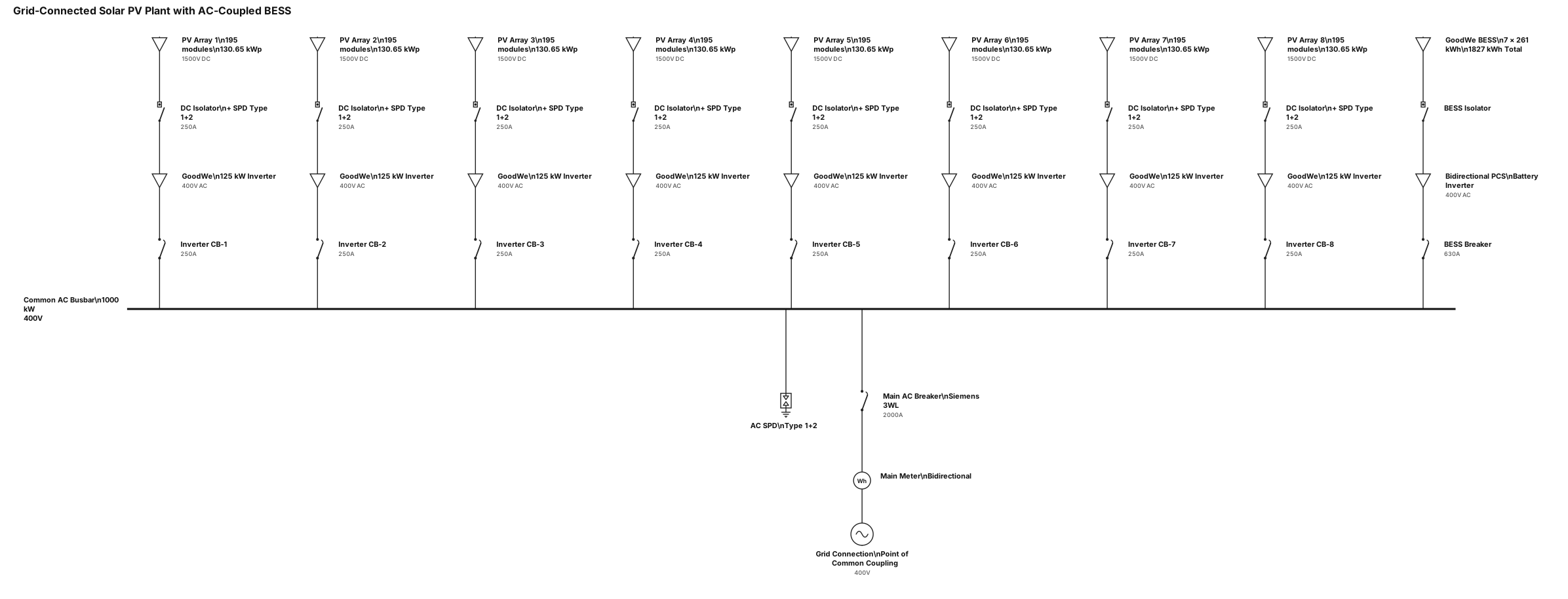
Create a professional electrical Single Line Diagram (SLD) for a grid-connected solar PV power plant with AC-coupled battery energy storage. Use standard IEC electrical symbols and a clear, engineering-grade layout. 1. Solar PV Array * Total number of PV modules: 1,560 modules. * Module manufacturer: aiko. * Module rated power: 670 Wp each. * Total installed DC capacity: 1,045.2 kWp. * Distribute the PV array across 8 GoodWe 125 kW inverters. * Show the PV strings connected to the respective inverters, with appropriate DC isolators and DC surge protection devices (SPDs) where applicable. 2. PV Inverters * Quantity: 8 units. * Manufacturer: GoodWe. * Rated AC power: 125 kW per inverter. * Total inverter AC capacity: 1,000 kW. * Provide a dedicated 250 A circuit breaker for each inverter. * Connect all eight inverter feeders to a common AC distribution busbar. 3. Main AC Protection * Main circuit breaker: 2,000 A. * Manufacturer: Siemens. * Connect the main breaker between the common AC busbar and the main point of connection. * Show appropriate AC surge protection, grounding, and protection devices as required by the final electrical design. 4. Battery Energy Storage System (BESS) * Manufacturer: GoodWe. * Battery energy capacity: 7 unit of261 kWh per battery system. * Configuration: AC-coupled battery storage system. * Show the battery system connected on the AC side through its dedicated bidirectional battery inverter / PCS, with the required AC circuit breaker, isolation, and protection. * Clearly distinguish the battery system from the PV inverters. 5. Metering and Grid Connection
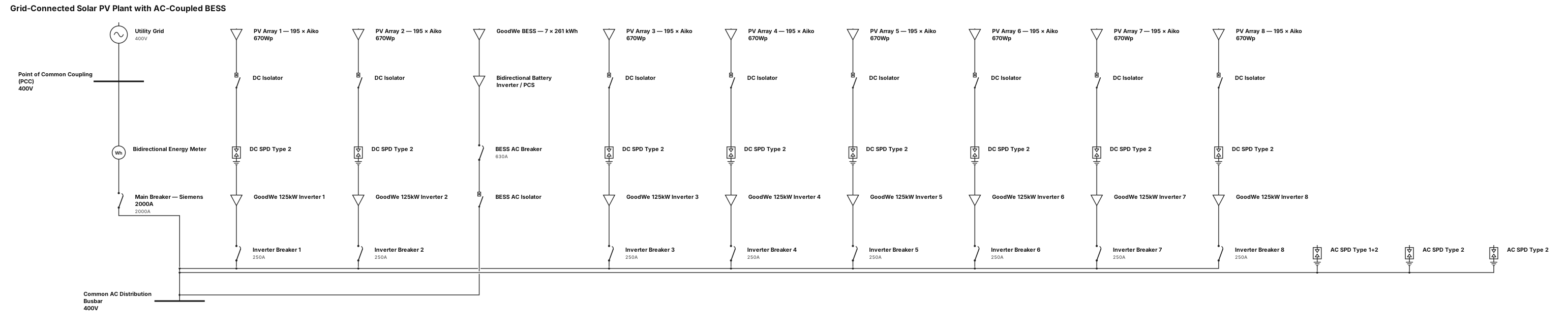
Create a professional electrical Single Line Diagram (SLD) for a grid-connected solar PV power plant with AC-coupled battery energy storage. Use standard IEC electrical symbols and a clear, engineering-grade layout. 1. Solar PV Array * Total number of PV modules: 1,560 modules. * Module manufacturer: aiko. * Module rated power: 670 Wp each. * Total installed DC capacity: 1,045.2 kWp. * Distribute the PV array across 8 GoodWe 125 kW inverters. * Show the PV strings connected to the respective inverters, with appropriate DC isolators and DC surge protection devices (SPDs) where applicable. 2. PV Inverters * Quantity: 8 units. * Manufacturer: GoodWe. * Rated AC power: 125 kW per inverter. * Total inverter AC capacity: 1,000 kW. * Provide a dedicated 250 A circuit breaker for each inverter. * Connect all eight inverter feeders to a common AC distribution busbar. 3. Main AC Protection * Main circuit breaker: 2,000 A. * Manufacturer: Siemens. * Connect the main breaker between the common AC busbar and the main point of connection. * Show appropriate AC surge protection, grounding, and protection devices as required by the final electrical design. 4. Battery Energy Storage System (BESS) * Manufacturer: GoodWe. * Battery energy capacity: 7*261 kWh per battery system. * Configuration: AC-coupled battery storage system. * Show the battery system connected on the AC side through its dedicated bidirectional battery inverter / PCS, with the required AC circuit breaker, isolation, and protection. * Clearly distinguish the battery system from the PV inverters. 5. Metering and Grid Connection * Include a bidirectional energy meter at the main point of connection to the utility grid. * Show the utility grid, point of common coupling (PCC), and the main metering arrangement. * Clearly indicate the direction of power flow for both grid export and battery charging.

I have a Mitsubishi FX5U 32M PLC, an MGS1600GY magnetic sensor, 2 BLVD KRD Type R motor drivers, a motor, and 2 BLHM5100KC GFS motors. I’m going to assemble them as an AGV. With your intelligence, make the ladder diagram in detail and make sure the motor PID works well.