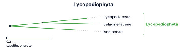
Draw a phylogenetic tree diagram of:lycopodiophyta
NODE ARCHIVE · REAL DIAGRAM BRIEFS
Diagram Examples from Real Visitor Prompts
Browse eligible diagrams shared by FreeDiagram visitors, inspect the exact prompts, and build your own version.
Browse 3275 real creationsCOMMUNITY OUTPUTS · EXACT PROMPTS
All visitor creations
Showing 433–456 of 3275. No stock examples or system defaults. Choose a tool, study a real result, then reopen its prompt as your starting point.
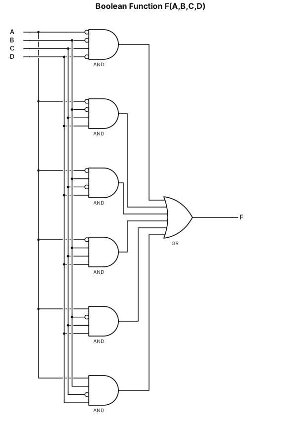
F(A ,B ,C ,D) = A'B'CD' + A'B'CD + A'BC'D + A'BCD + AB'CD + ABC'D
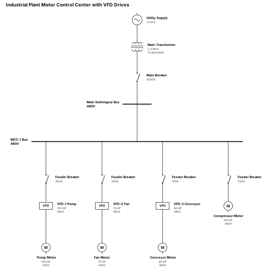
Industrial plant motor control center with VFD drives
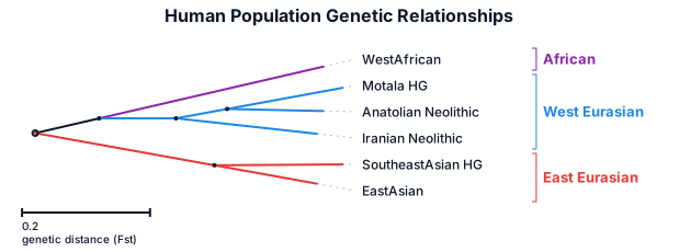
Create a phylogenetic tree showcasing the genetic relationships between these ancient and modern human populations - 1. West African populations, 2. Iranian Neolithic (Zagros), 3. Anatolian Neolithic (Barcın), 4. European Mesolithic Hunter-Gatherers (Motala), 5. Modern Southeast Asian Hunter-Gatherers and 6. Modern East Asian populations.
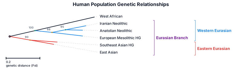
Create a phylogenetic tree showcasing the genetic relationships between these ancient and modern human populations - 1. West African populations, 2. Iranian Neolithic (Zagros), 3. Anatolian Neolithic (Barcın), 4. European Mesolithic Hunter-Gatherers (Motala), 5. Modern Southeast Asian Hunter-Gatherers and 6. Modern East Asian populations. Within the graphic both Western and Eastern Eurasian should descend from a single Eurasian Branch
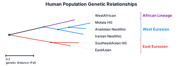
Create a phylogenetic tree showcasing the genetic relationships between these ancient and modern human populations - 1. West African populations, 2. Iranian Neolithic (Zagros), 3. Anatolian Neolithic (Barcın), 4. European Mesolithic Hunter-Gatherers (Motala), 5. Modern Southeast Asian Hunter-Gatherers and 6. Modern East Asian populations
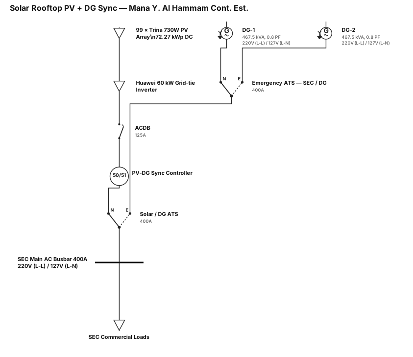
A single-line diagram for a SOLAR ROOFop project Mana Y. Al Hammam Cont. Est. commercial building Solar grid tie-in with inverter huawei 60 kw dc 72.27 kwp 99 * 730 trina pv module,acdb - 125 A,PV-DG SYNC CONTROLLER PANEL TO SYNC sec 220 v (L-L)/127 V (L-N) MAIN AC BUS BAR -400 A, Existing ATS (FOR DG - SEC MAnual ) 2 NOS DG SAME CAPCITY (467.5 KA 0.8 PF,220 V (L-L),127 V(L-N) WITH EMERGENCY ATS FOR SEC - DG , NOW WE NEED SOLAR TO SEC TO DG CONFIDURED ATS
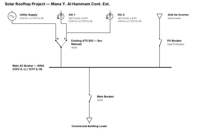
A single-line diagram for a SOLAR ROOFop project Mana Y. Al Hammam Cont. Est. commercial building sec 220 v (L-L)/127 V (L-N) MAIN AC BUS BAR -400 A, Existing ATS (FOR DG - SEC MAnual ) - 2 NOS DG SAME (467.5 KA 0.8 PF,220 V (L-L),127 V(L-N)
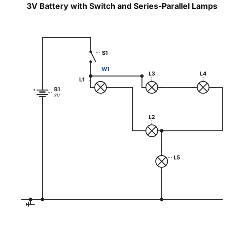
Draw a schematic diagram. A single 3V battery power source connects to a switch. After the switch, the wire splits into two parallel branches. The first branch has two light bulbs in series. The second branch has two light bulbs in series. These two branches merge back into a single path. This path connects to a fifth light bulb in series, which then connects back to the negative terminal of the 3V battery
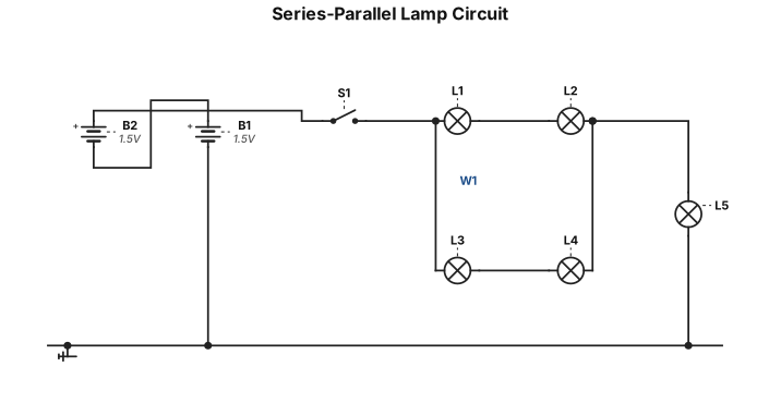
Draw a schematic diagram. Two batteries are connected in series. The positive terminal connects to a switch. After the switch, the wire splits into two parallel branches. The first branch has two light bulbs connected in series. The second branch has two light bulbs connected in series. These two branches merge back together into a single path. This path connects to a fifth light bulb in series, which then connects back to the negative terminal of the battery bank
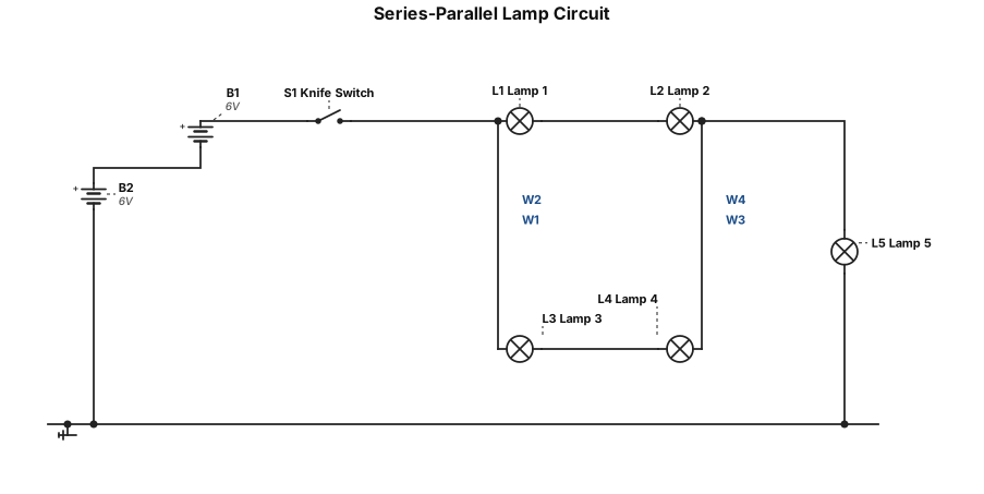
This diagram shows a combination series-parallel circuit powered by two batteries connected in series at the bottom right. The current flows from the positive terminal of the batteries through a single knife switch, after which the main wire splits into two parallel branches on the left. The top branch contains two light bulbs connected in series, and the middle branch similarly contains two light bulbs connected in series. The current coming out of both of these parallel pairs then merges back into a single wire before passing through a fifth individual light bulb on the right side, which finally completes the loop by connecting back to the negative terminal of the battery bank.
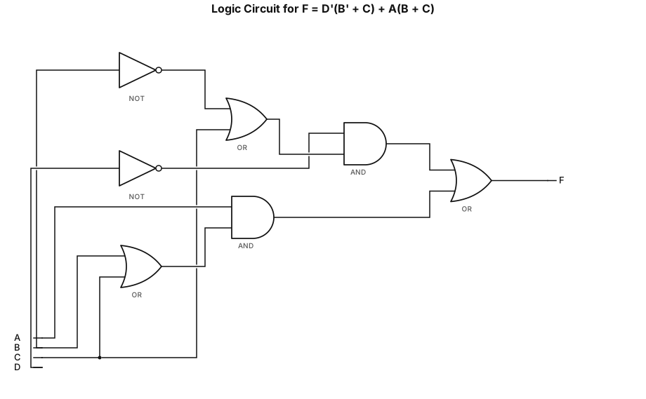
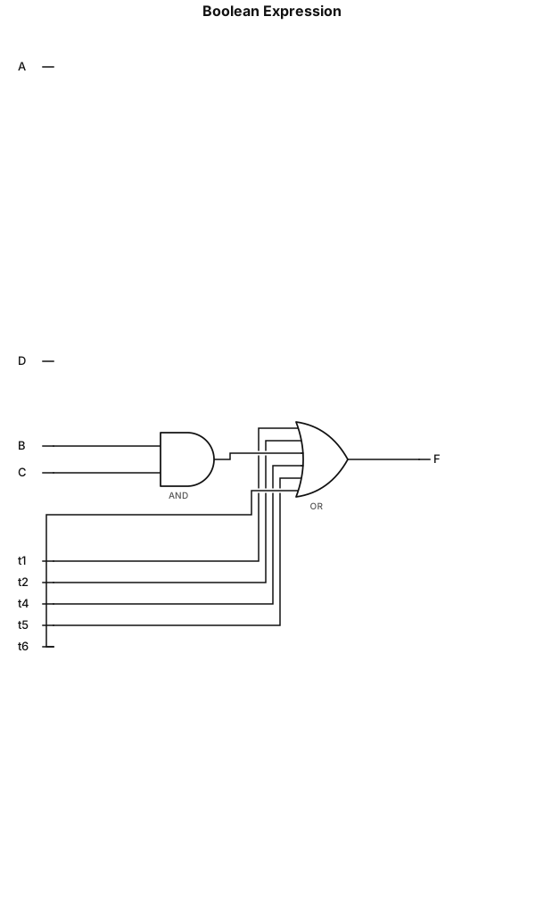
Draw the logic circuit diagram for F = D'(B' + C) + A(B + C), strictly using 2 inputs only
B'·D' + A'·C + B·C + A·D' + A'·B·D + A·B'·C'
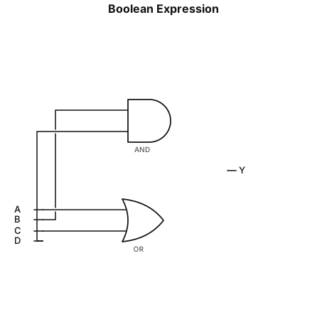
A + C + B·D + B'·D'
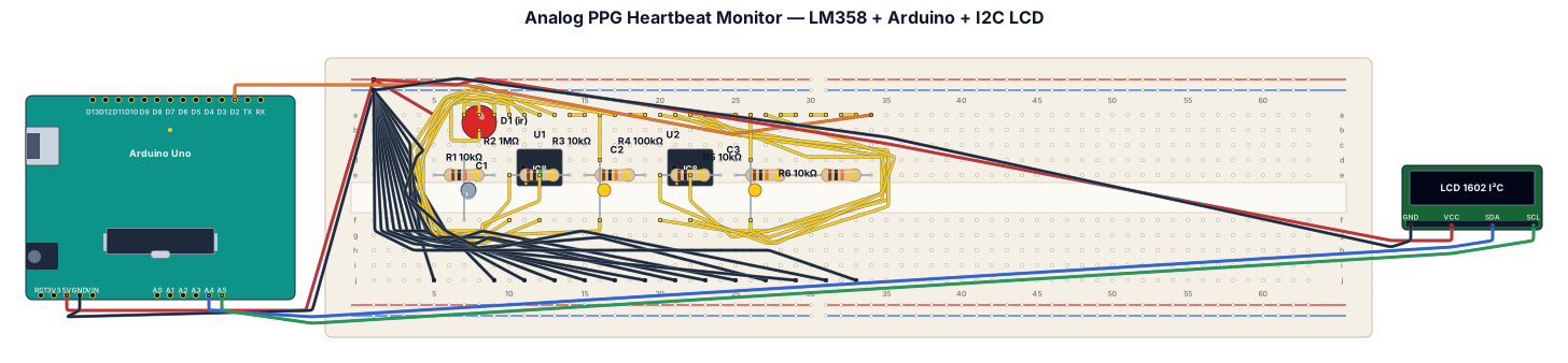
This project presents an analog opto-electronic heartbeat monitor designed using core Analog Integrated Circuit principles.It acquires micro-volt capillary blood volume variations through a non-invasive optical Photoplethysmography (PPG) sensor front-end.A passive RC high-pass network eliminates massive static DC offsets originating from ambient illumination and tissue reflection.An LM358 operational amplifier active inverting stage provides a controlled voltage gain of $40\text{ dB}$.A parallel feedback capacitor implements an active low-pass filter to suppress $50\text{ Hz}$ power line hum and high-frequency noise.A second LM358 op-amp configured as a non-inverting Schmitt trigger uses positive feedback for clean pulse shaping.Adjustable hysteresis prevents false double-triggering caused by motion artifacts or light flicker.An Arduino microcontroller measures time intervals between pulse rising edges using external interrupts.The system computes real-time Beats Per Minute (BPM) and displays live biomedical telemetry on an I2C LCD screen.This hybrid analog-digital system successfully bridges core college circuit analysis theory with a practical, low-cost biomedical device.
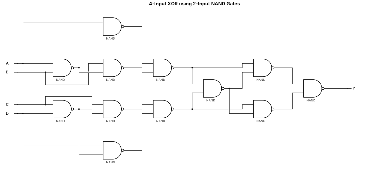
Draw a gate-level schematic of Y = A XOR B XOR C XOR D using only 2-input NAND gates.
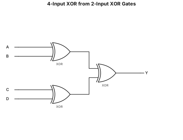
Draw a gate-level schematic of Y = A XOR B XOR C XOR D using only 2-input XOR gates.
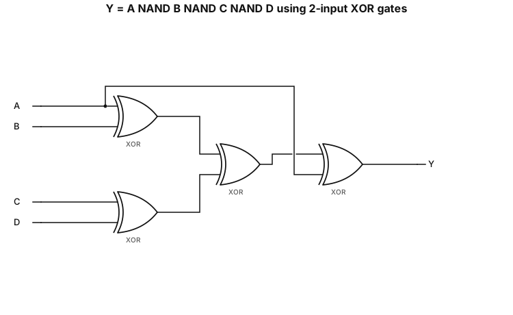
Draw a gate-level schematic of Y = A NAND B NAND C NAND D using only 2-input XOR gates.
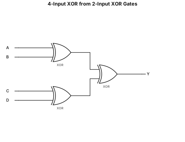
Draw a gate-level schematic of Y = A XOR B XOR C XOR D using only 2-input XOR gates.
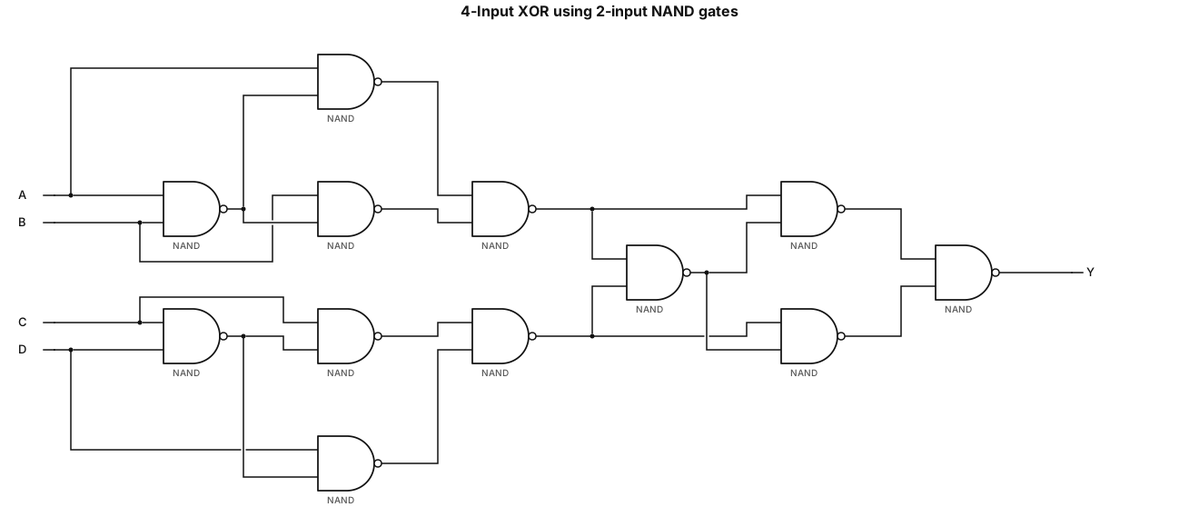
Draw a gate-level schematic of Y = A XOR B XOR C XOR D using only 2-input NAND gates.
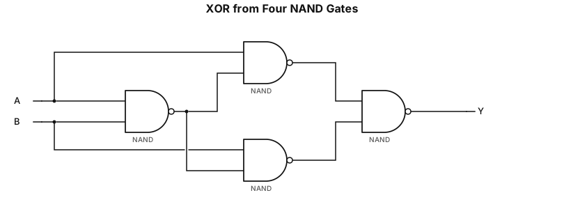
Draw a transistor-free gate-level schematic of Y = A XOR B using exactly four 2-input NAND gates. Show all connections. Do not use XOR gate symbols
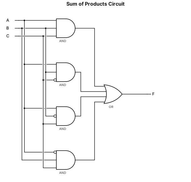
Draw an AND gate for each term (raw in the truth table) with a 1 in the result column Wire the AND gates to the appropriate inputs Feed the output of all the AND gates into an OR gate
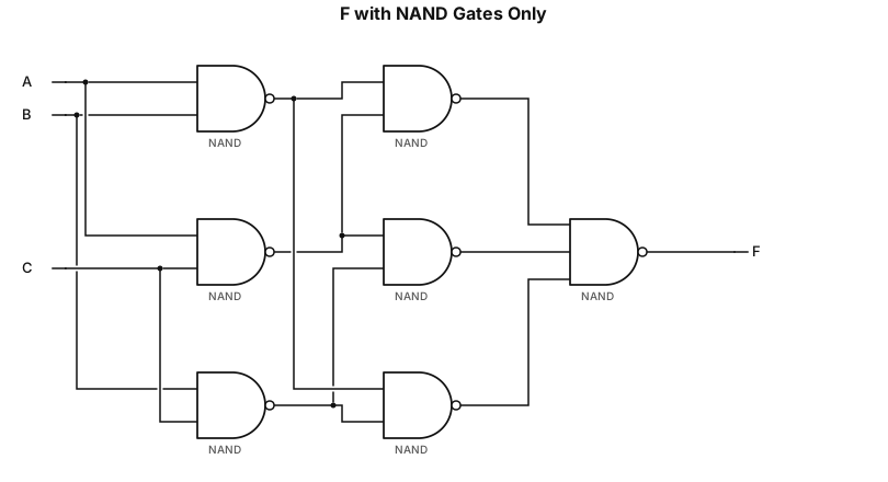
F = A'B'C' + ABC' + AB'C + A'BC NAND gates only
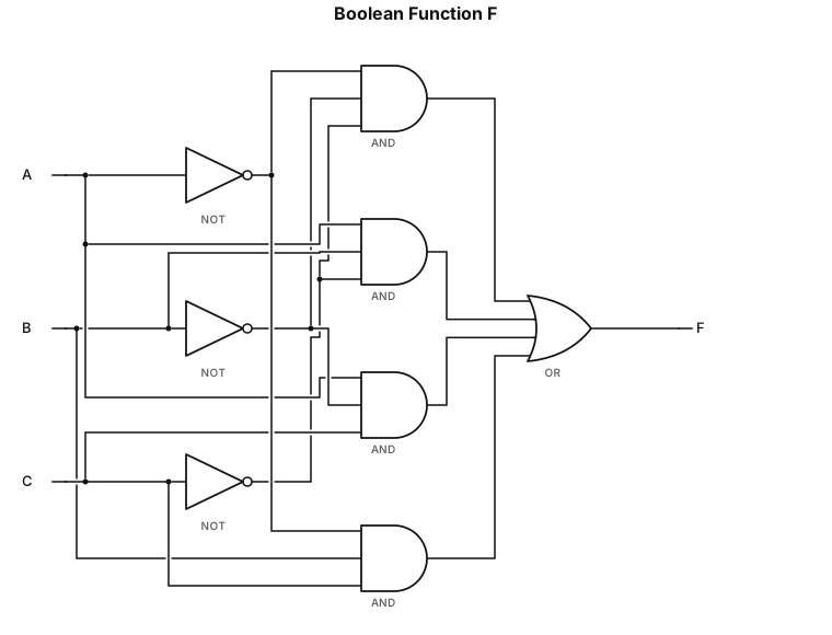
F = A'B'C' + ABC' + AB'C + A'BC