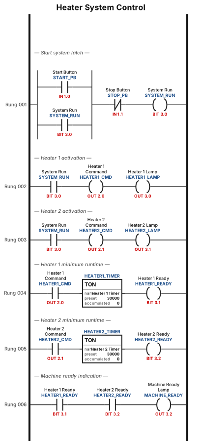
1. Single Start Button: a. One push-button will initiate the entire heating process. 2. Heater Activation: a. Both heaters must turn on automatically when the system is started. b. Each heater should have a corresponding indicator lamp to show it is active. 3. Heating Time Control: a. Each heater must operate for a minimum of 30 seconds before the system can be considered "ready." 4. Machine Ready Indication: a. After both heaters have completed the minimum 30-second runtime (simultaneously or sequentially, depending on design), a green indicator lamp should turn on to signal that the machine is ready for operation.
NODE ARCHIVE · REAL DIAGRAM BRIEFS
Diagram Examples from Real Visitor Prompts
Browse eligible diagrams shared by FreeDiagram visitors, inspect the exact prompts, and build your own version.
Browse 3261 real creationsCOMMUNITY OUTPUTS · EXACT PROMPTS
Ladder Logic
Showing 25–48 of 57. No stock examples or system defaults. Choose a tool, study a real result, then reopen its prompt as your starting point.
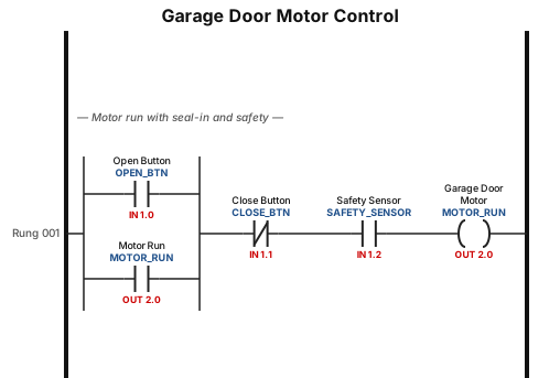
Title: Garage Door Motor Control (Digital I/O Practice) Scenario: You are asked to design a control system for a garage door motor. The system should behave as follows: The motor runs when the Open Button is pressed. The motor stops when the Close Button is pressed. The motor will only run if the Safety Sensor is clear (not blocked). Inputs: Open Button (momentary pushbutton) Close Button (momentary pushbutton) Safety Sensor (closed = clear, open = blocked) Outputs: Garage Door Motor Your Task: Draw the ladder logic diagram for this system using contacts and coils. Include the Open Button, Close Button, and Safety Sensor as inputs. Include the Garage Door Motor as the output. Make sure the motor stays on after the Open Button is pressed. Label all inputs and outputs clearly.
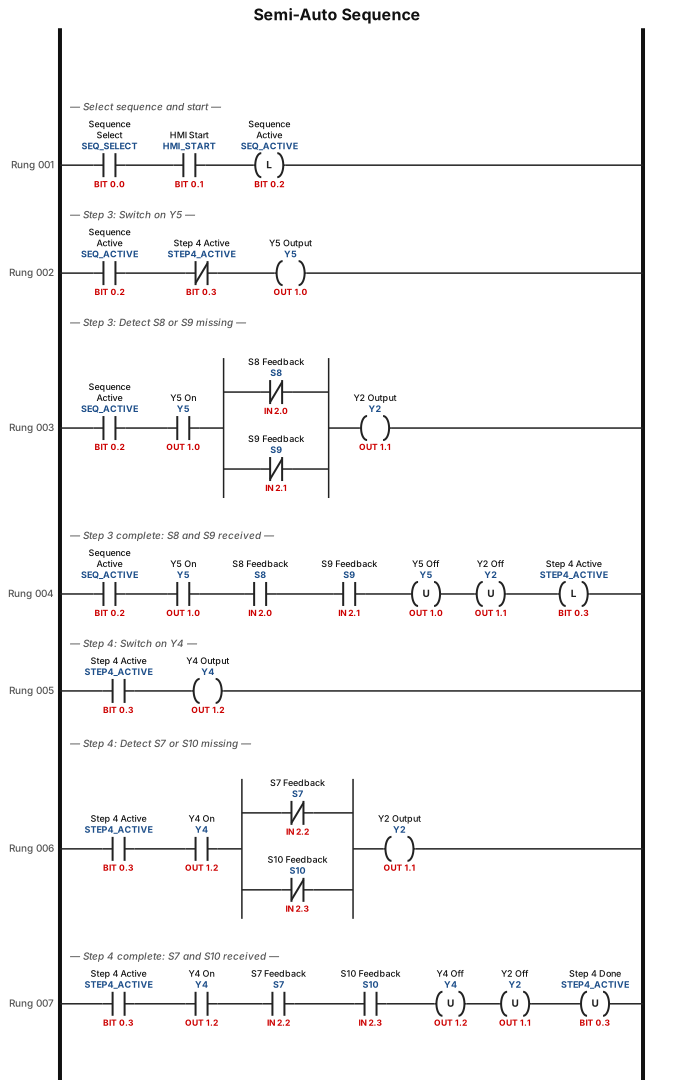
1) Select the sequence in semi auto\ 2) press sequence start from HMI 3) Switch On Y5 on, Limit switch S7 & S10 changes to S8 & S9, In case S8 or S9 is missing Y2 On. If S8 & S9 both limit switch feedback received Switch off Y5 and Y2 4) Switch on Y4 Limit switch S8 & S9 changes to S7 & S10, In case S7 or S10 is missing Y2 On. If S7 & S10 both limit switch feedback received Switch off Y4 and Y2 5) Repeat step 3
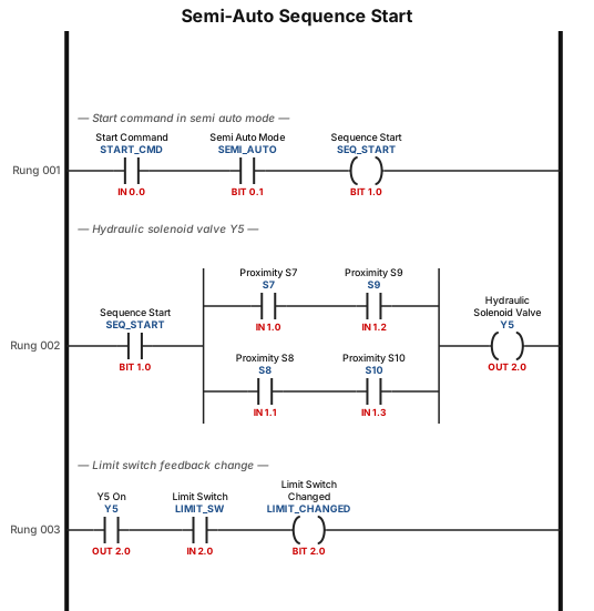
Sequence start command in semi auto mode. Y5 -Hydraulic solenoid valve-on in case S7 & S9 or S8 & S10 proximity switch feedback once Y5 on the limit switch feedback change
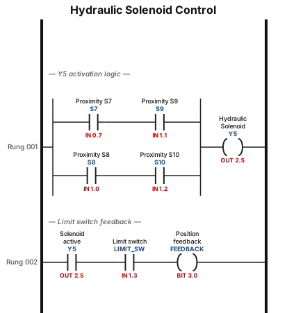
Y5 (Hydraulic solenoid valve) on in case S7 & S9 or S8 & S10 proximity switch feedback once Y5 on the limit switch feedback change
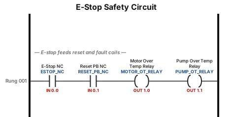
A NC e-stop that feeds four terminal blocks one goes to NC reset PB the two others feed the relay coils one for motor over temp the other coil is pump over temp
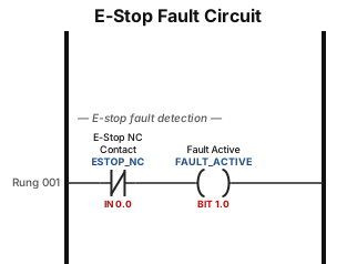
A NC e-stop that feeds a fault circuit
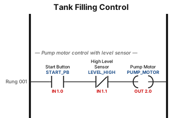
A ladder logic program for a filling tank by a pump motor and a sensor to close a pump
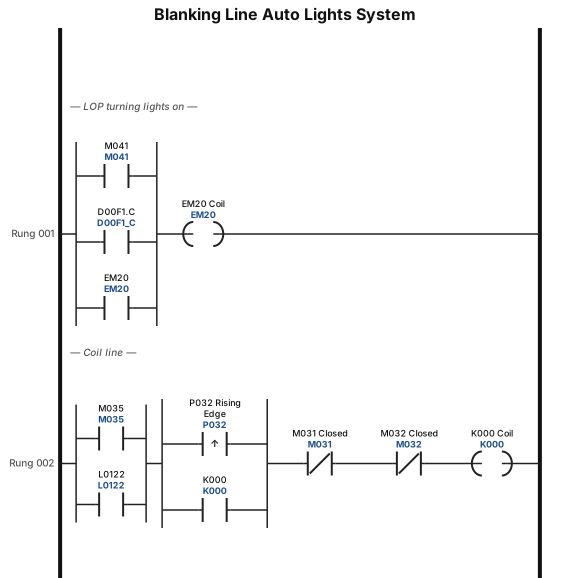
A ladder logic program for a Blanking line Auto lights system: LOP turning lights on: M041, D00F1.C & EM20 all connected in parallel to each other at the start of the rung, all powering EM20 coil at the end of the rung. Coil line: M035, L0122 normal open contactors connected in parallel to each other, rising edge contactor P032 connected in series with M035 & L0122 which are in parallel, K000 normal open contactor which is in parallel with P032 connected in series with M035 & L0122, all this connected in series with M031 closed contactor and connected in series with M032 closed contactor which all these contactors are connected to one coil K000 at the end of the rung
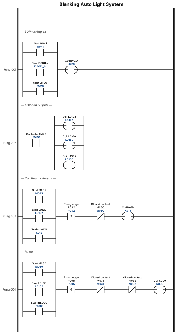
A ladder logic program for a Blanking Auto light system: LOP Turning on: start buttons (M041, D00f1.c, EM20) powering a coil (EM20), on the second rung we have a normal open contactor (EM20) powering coil L0122, L0160 & L01C5 all parallel to each other. Coil line turning on: Start buttons M035, L0122 connected in parallel P032 As rising edge pulse connected in series with them, K019 connected in parallel with them after P032, closed contact M03c connected in series with all of them and K019 coil at the end. Pilers: Start buttons M030, L01C5 connected in parallel P005 As rising edge pulse connected in series with them, K000 connected in parallel with them after P005, closed contact M031 & M032 connected in series with all of them and K000 coil at the end.
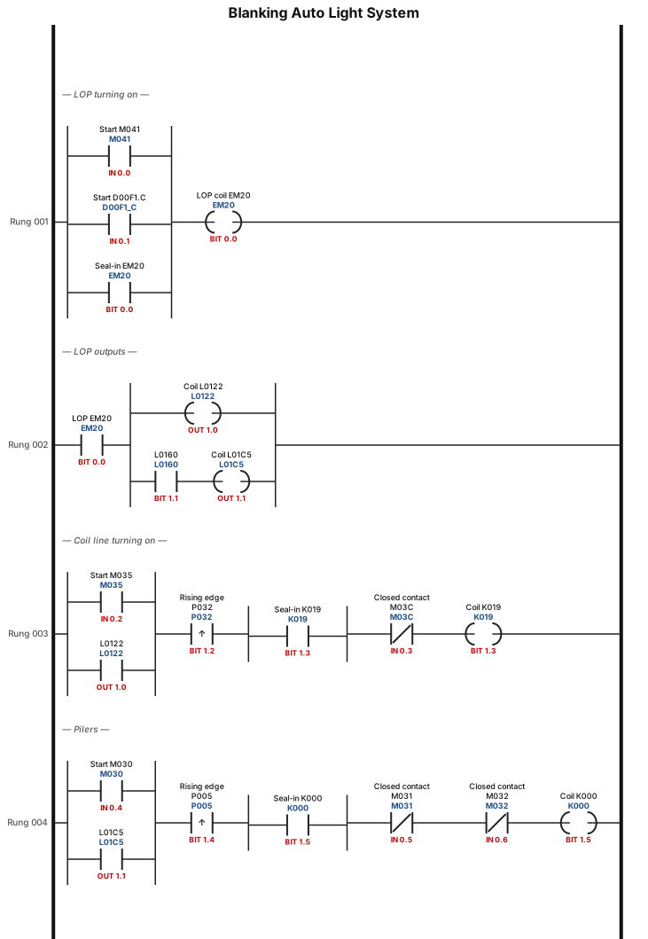
A ladder logic program for a Blanking Auto light system: LOP Turning on: start buttons (M041, D00f1.c, EM20) powering a coil (EM20), on the second rung we have a normal open contactor (EM20) powering coil (L0122 in parallel with, L0160 & L01C5). Coil line turning on: Start buttons M035, L0122 connected in parallel P032 As rising edge pulse connected in series with them, K019 connected in parallel with them after P032, closed contact M03c connected in series with all of them and K019 coil at the end. Pilers: Start buttons M030, L01C5 connected in parallel P005 As rising edge pulse connected in series with them, K000 connected in parallel with them after P005, closed contact M031 & M032 connected in series with all of them and K000 coil at the end.
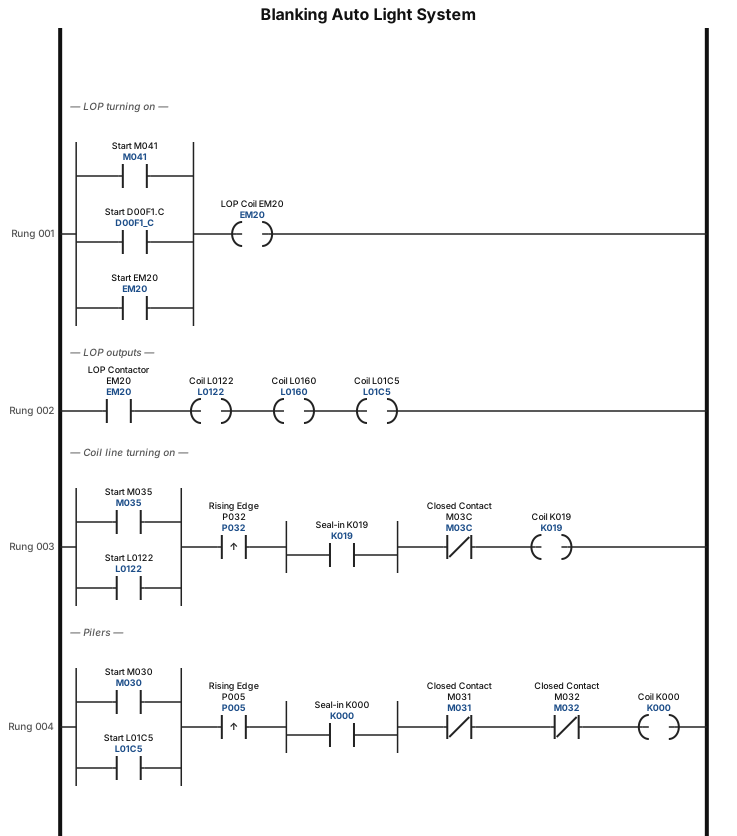
A ladder logic program for a Blanking Auto light system: LOP Turning on: start buttons (M041, D00f1.c, EM20) powering a coil (EM20), on the second rung we have a normal open contactor (EM20) powering coil (L0122, L0160 & L01C5). Coil line turning on: Start buttons M035, L0122 connected in parallel P032 As rising edge pulse connected in series with them, K019 connected in parallel with them after P032, closed contact M03c connected in series with all of them and K019 coil at the end. Pilers: Start buttons M030, L01C5 connected in parallel P005 As rising edge pulse connected in series with them, K000 connected in parallel with them after P005, closed contact M031 & M032 connected in series with all of them and K000 coil at the end.
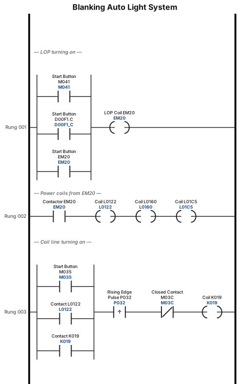
A ladder logic program for a Blanking Auto light system: LOP Turning on: start buttons (M041, D00f1.c, EM20) powering a coil (EM20), on the second rung we have a normal open contactor (EM20) powering coil (L0122, L0160 & L01C5). Coil line turning on: Start buttons M035, L0122 connected in parallel P032 As rising edge pulse connected in series with them, K019 connected in parallel with them, closed contact M03c connected in series with all of them and K019 coil at the end.
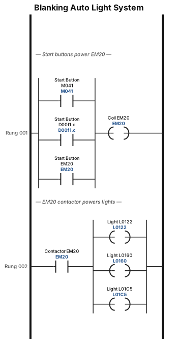
A ladder logic program for a Blanking Auto light system: start buttons (M041, D00f1.c, EM20) powering a coil (EM20), on the second rung we have a normal open contactor (EM20) powering coil (L0122, L0160 & L01C5)
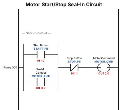
A motor start/stop seal-in circuit with a normally open start button, a normally closed stop button, and a seal-in contact around the start button
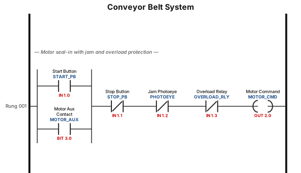
A ladder logic program for a conveyor belt system: start button seals in the motor, a photoeye stops the belt when a jam is detected, and an overload relay trips the circuit
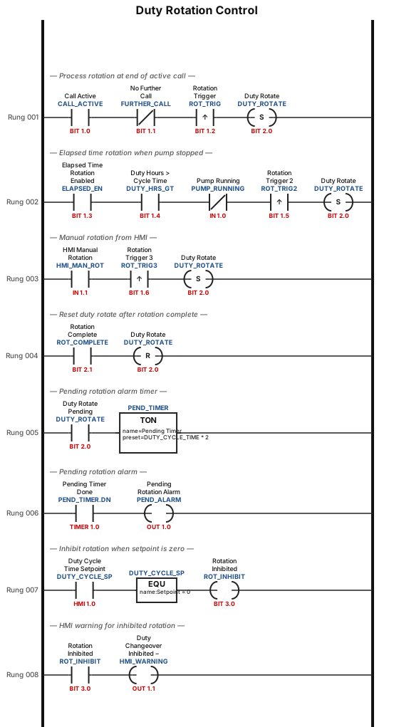
Verify Process Rotation: at the end of an active call, if there is no further call, Duty rotates once ready for the next call Verify Elapsed Time Rotation: when selected, Duty rotates once the Duty Hours Run exceeds the HMI Adjustable Duty Cycle Time, and rotation initiates only once the pump has stopped Verify operator can force a manual rotation from the HMI Verify an alarm is raised if Duty Rotation is pending for 2x the Duty Cycle Time Setpoint Verify entering 0 in the Duty Cycle Time Setpoint inhibits rotation and displays the HMI warning 'Duty Changeover Inhibited – Enter a Value Greater than 0 in the Duty Cycle Time'
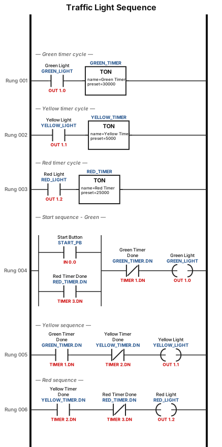
A three-step traffic light PLC sequence using timers: green for 30 seconds, yellow for 5 seconds, red for 25 seconds, then repeat
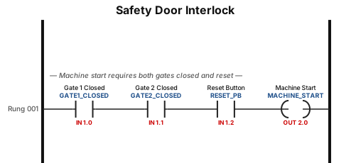
A safety door interlock circuit where a machine cannot start unless two safety gate switches are closed and a reset button is pressed
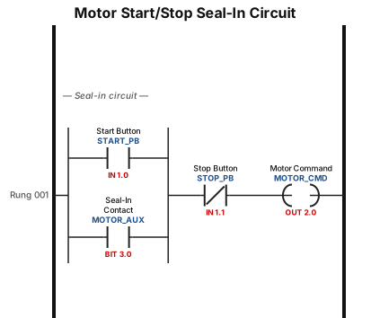
A motor start/stop seal-in circuit with a normally open start button, a normally closed stop button, and a seal-in contact around the start button
![Ladder Logic example: ]packake on conveyor sensor at beginning op push staty starts if senos detects over load must be used must use pb3 estop](https://psvtykrtciekraoilfux.supabase.co/storage/v1/object/public/gallery-assets/freediagram/feed/1428933c-654b-45fa-b532-5568260da686.svg)
]packake on conveyor sensor at beginning op push staty starts if senos detects over load must be used must use pb3 estop
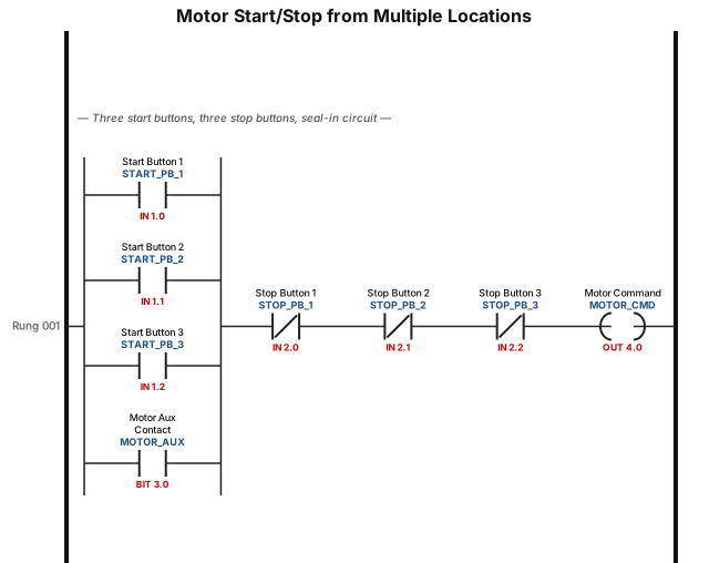
Create a single rung program that can start a motor from three different start locations (any one of which can start the motor individually), and three stop buttons (Any one of which can stop the motor). The Motor will continue to run after the start button is released
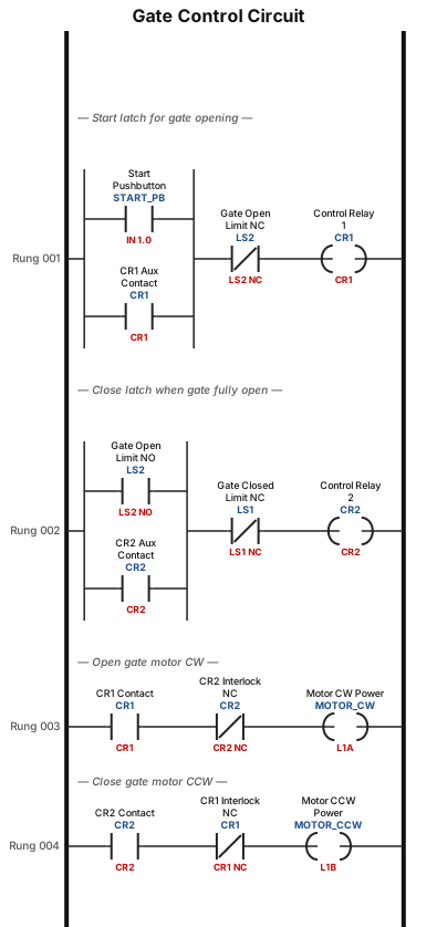
A reversible motor is used to open and close a gate. The motor has three terminals: L1A, L1B, and L2. When L2 is connected to the ground and power is applied to L1A, the motor runs clockwise, CW, direction, opening the gate. When power is applied to L1B, the motor runs counterclockwise, CCW, direction, closing the gate. The gate has two limit switches: LS1 is activated when the gate is closed, and LS2 is activated when the gate is open. Each limit switch has one normally open. NO, contact and one normally closed, NC, contact. Two control relays, CR1 and CR2, are used in the gate control circuit. These relays have two NO contacts and two NC contacts. A NO pushbutton START switch is used to initiate the opening of the gate. Draw a ladder diagram that will open the gate after a momentary closure of the START switch, close the gate immediately after the gate is fully open, and turn OFF the power to the motor when the gate is closed. Your circuit must include an interlock feature that will not allow simultaneous application of power on L1A and L1B.
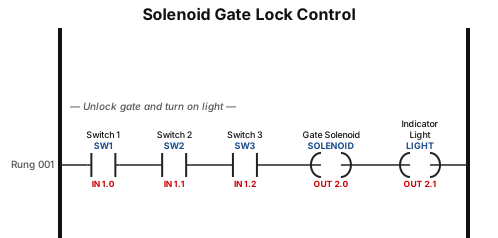
A solenoid-operated lock is used on the gate of an enclosed storage area. When the solenoid is activated, the gate is unlocked, and a light goes ON. Three pushbutton switches are used in the solenoid control circuit, SW1, SW2, and SW3. The three switches are located such that a single operator can close only one switch at a time, two operators are required to close two switches, and three operators are required to close all three switches.