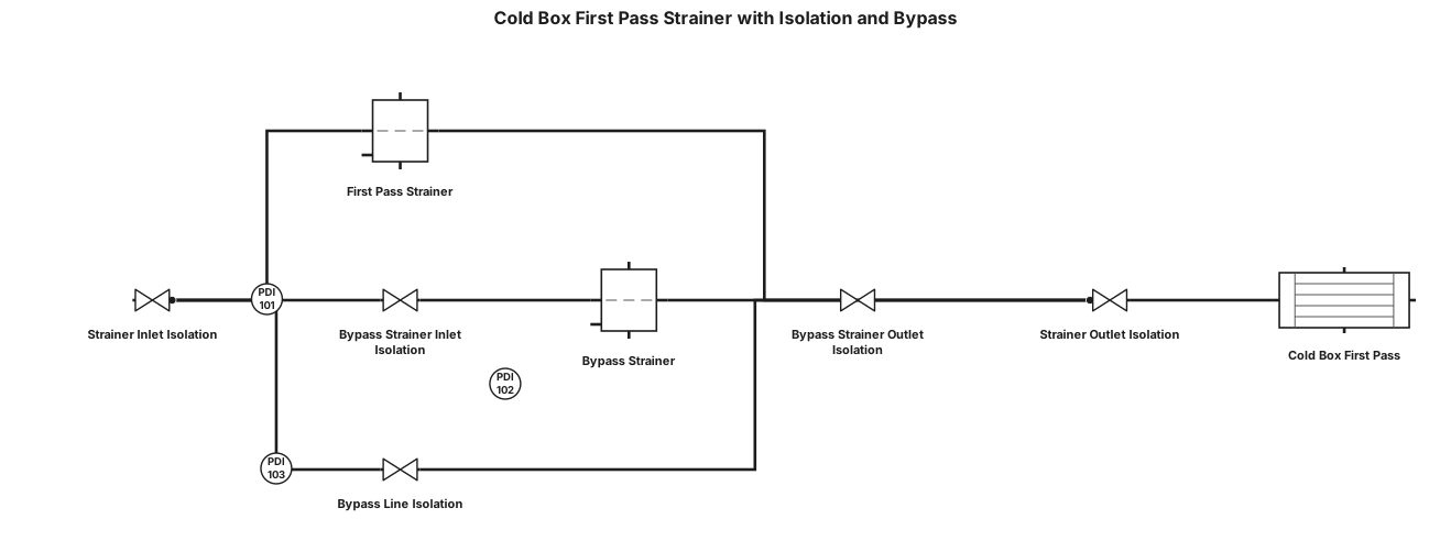
there is cold box its first pass gas inlet have a staainer and i want to make isolation for the stainer and also make a bypass also stainer on bypass
NODE ARCHIVE · REAL DIAGRAM BRIEFS
Diagram Examples from Real Visitor Prompts
Browse eligible diagrams shared by FreeDiagram visitors, inspect the exact prompts, and build your own version.
Browse 3261 real creationsCOMMUNITY OUTPUTS · EXACT PROMPTS
Pid
Showing 25–48 of 142. No stock examples or system defaults. Choose a tool, study a real result, then reopen its prompt as your starting point.
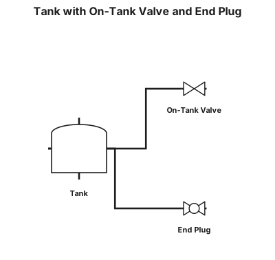
make a tank which at right side of tank there is on-tank valve attached without any space and at left side of the tank there is and end-plug attached without any space.
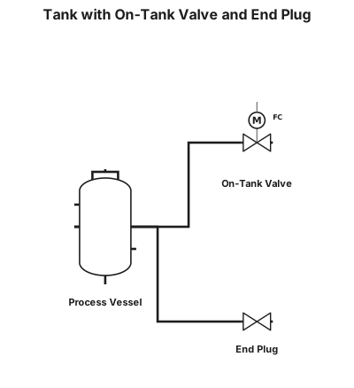
make a vessel which at right side of tank there is on-tank valve attached without any space and at left side of the tank there is and end-plug attached without any space.
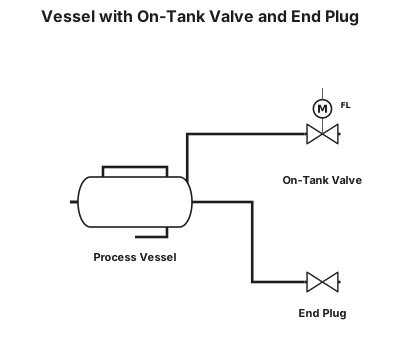
make a vessel which at oneside of tank there is on-tank valve and at the other side of tank there is end plug(both are attached to the tank)
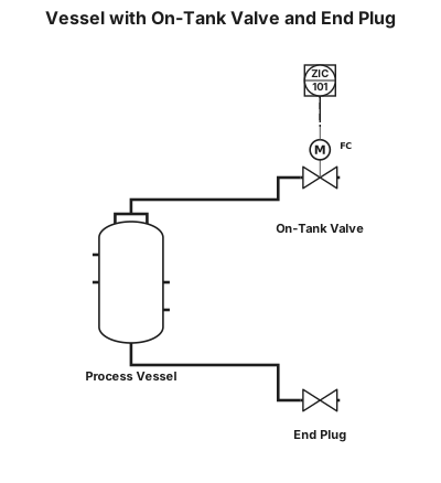
make a vessel which at oneside of tank there is on-tank valve and at the other side of tank there is end plug
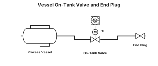
make a vessel onside fo tank on-tank valve the other side of tank end plug
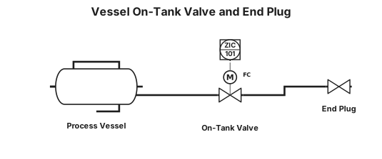
make a vessel onside on-tank valve the other side end plug
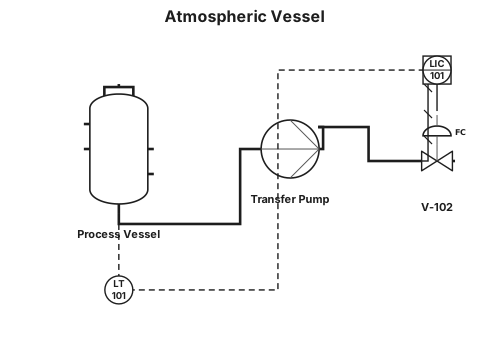
make a vessel
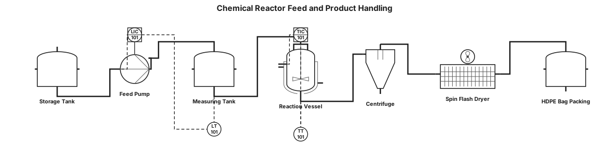
A P&ID for a chemical reactor feed system: storage tank , measuring tank , reaction vessel with stirrer and temperature guage, discharge to centriguge, spin flash dryer , packing in hdpe bags
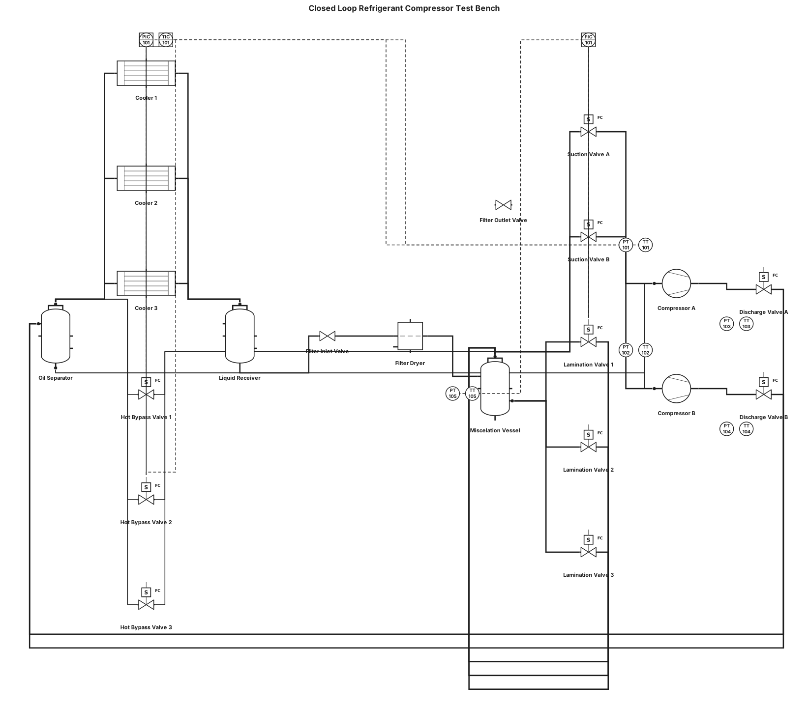
A P&ID for a closed loop refrigerant gas compressors test bench, with two compressors parallel positions. Pressure and temperature sensors at the suction and discharge of every compressor. Electrovalves at every inlet (before sensors) and outlet lines (after sensors) of the compressors. After the discharge line union, and before the coolers, an oil separator vessel. After the oil separator, three coolers in parallel. After coolers, a liquid receiver vessel. After liquid receiver, a filter with manual valves for maintenance. After exit filter valve, pressure and temperature sensors. After sensors, three lamination electrovalves in parallel. After valves, a miscelation vessel. After miscelation vessel, back to che compressors. From the oil separator bottom, lines towards the compressors for oil injection. After the oil separator and before the coolers a bypass line with three hot bypass electrovalves that discharge into the miscelator vessel.
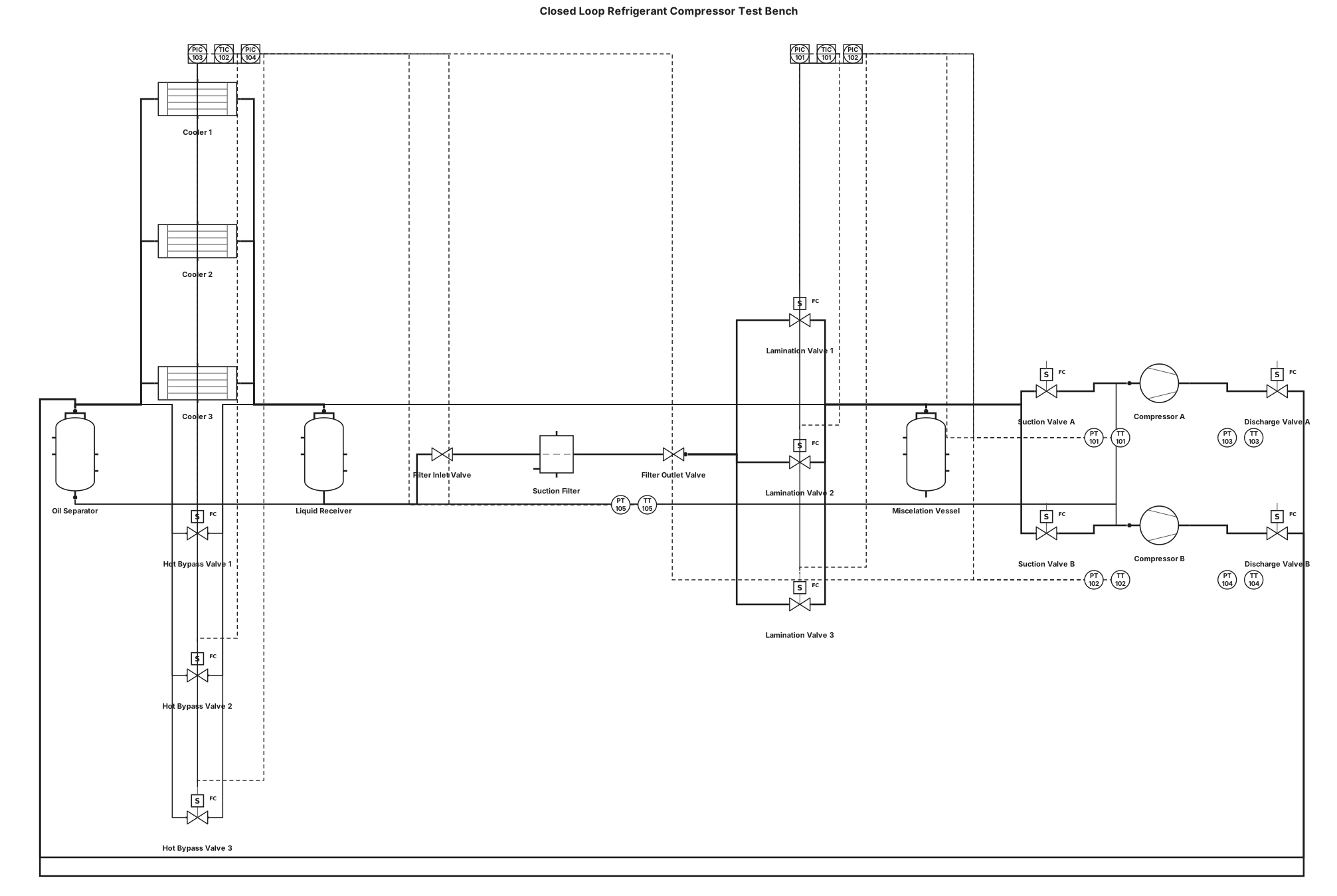
A P&ID for a closed loop refrigerant gas compressors test bench, with two compressors parallel positions. Pressure and temperature sensors at the suction and discharge of every compressor. Electrovalves at every inlet (before sensors) and outlet lines (after sensors) of the compressors. After the discharge line union, and before the coolers, an oil separator vessel. After the oil separator, three coolers in parallel. After coolers, a liquid receiver vessel. After liquid receiver, a filter with manual valves for maintenance. After exit filter valve, pressure and temperature sensors. After sensors, three lamination electrovalves in parallel. After valves, a miscelation vessel. After miscelation vessel, back to che compressors. From the oil separator bottom, lines towards the compressors for oil injection. After the oil separator, we have a bypass line with three hot bypass electrovalves that discharge into the miscelator vessel.
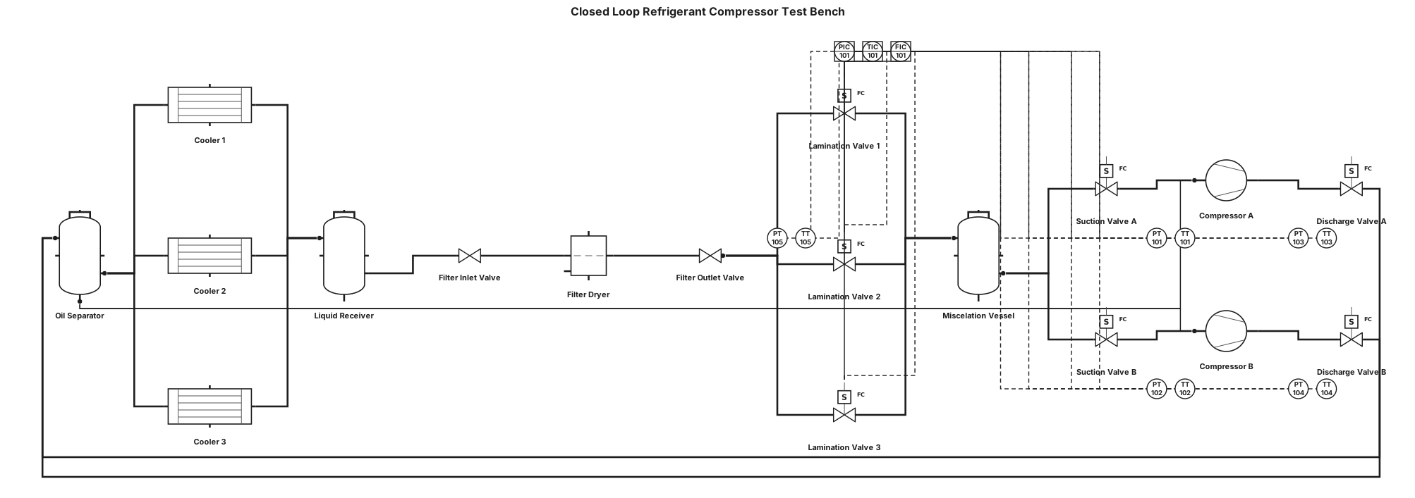
A P&ID for a closed loop refrigerant gas compressors test bench, with two compressors parallel positions. Pressure and temperature sensors at the suction and discharge of every compressor. Electrovalves at every inlet (before sensors) and outlet lines (after sensors) of the compressors. After the discharge line union, and before the coolers, an oil separator vessel. After the oil separator, three coolers in parallel. After coolers, a liquid receiver vessel. After liquid receiver, a filter with manual valves for maintenance. After exit filter valve, pressure and temperature sensors. After sensors, three lamination electrovalves in parallel. After valves, a miscelation vessel. After miscelation vessel, back to che compressors. From the oil separator bottom, lines towards the compressors for oil injection.
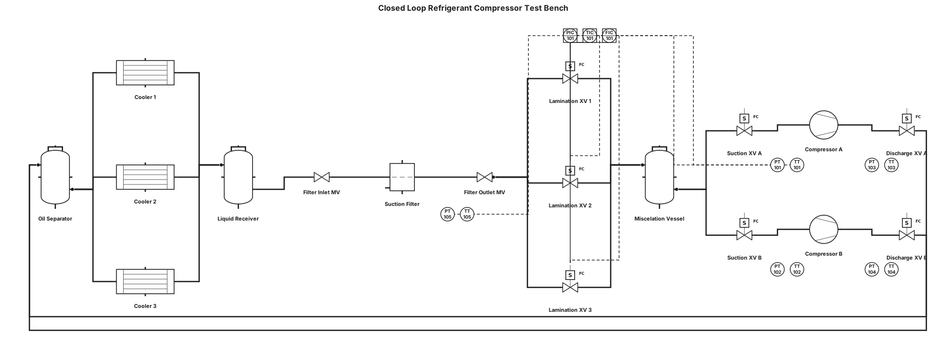
A P&ID for a closed loop refrigerant gas compressors test bench, with two compressors parallel positions. Pressure and temperature sensors at the suction and discharge of every compressor. Electrovalves at every inlet (before sensors) and outlet lines (after sensors) of the compressors. After the discharge line union, and before the coolers, an oil separator vessel. After the oil separator, three coolers in parallel. After coolers, a liquid receiver vessel. After liquid receiver, a filter with manual valves for maintenance. After exit filter valve, pressure and temperature sensors. After sensors, three lamination electrovalves in parallel. After valves, a miscelation vessel. After miscelation vessel, back to che compressors.
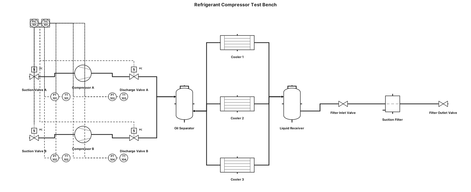
A P&ID for a closed loop refrigerant gas compressors test bench, with two compressors parallel positions. Pressure and temperature sensors at the suction and discharge of every compressor. Electrovalves at every inlet (before sensors) and outlet lines (after sensors) of the compressors. After the discharge line union, and before the coolers, an oil separator vessel. After the oil separator, three coolers in parallel. After coolers, a liquid receiver vessel. After liquid receiver, a filter with manual valves for maintenance.
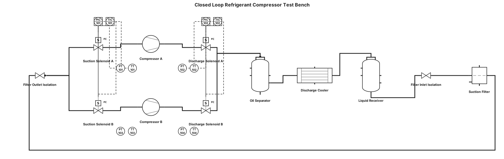
A P&ID for a closed loop refrigerant gas compressors test bench, with two compressors parallel positions. Pressure and temperature sensors at the suction and discharge of every compressor. Electrovalves at every inlet (before sensors) and outlet lines (after sensors) of the compressors. After the discharge line union, and before the coolers, an oil separator vessel. After coolers, a liquid receiver vessel. After liquid receiver, a filter with manual valves for maintenance.
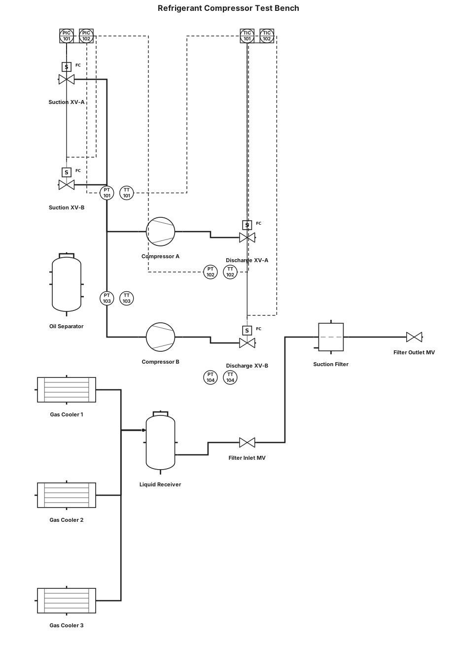
A P&ID for a closed loop refrigerant gas compressors test bench, with two compressors parallel positions, and three gas coolers in parallel. Pressure and temperature sensors at the suction and discharge of every compressor. Electrovalves at every inlet (before sensors) and outlet lines (after sensors) of the compressors. After the discharge line union, and before the coolers, an oil separator vessel. After coolers, a liquid receiver vessel. After liquid receiver, a filter with manual valves for maintenance.
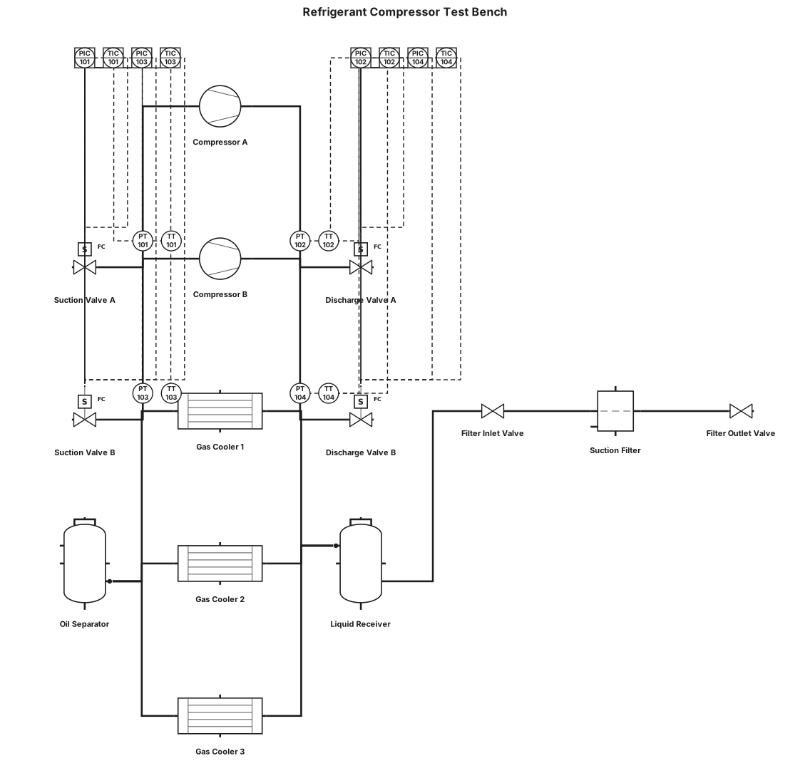
A P&ID for a closed loop refrigerant gas compressors test bench, with two compressors parallel positions. Pressure and temperature sensors at the suction and discharge of every compressor. Electrovalves at every inlet (before sensors) and outlet lines (after sensors) of the compressors. After the discharge line union, and before the coolers, an oil separator vessel. The gas cooler are three in parallel. After coolers, a liquid receiver vessel. After liquid receiver, a filter with manual valves for maintenance.
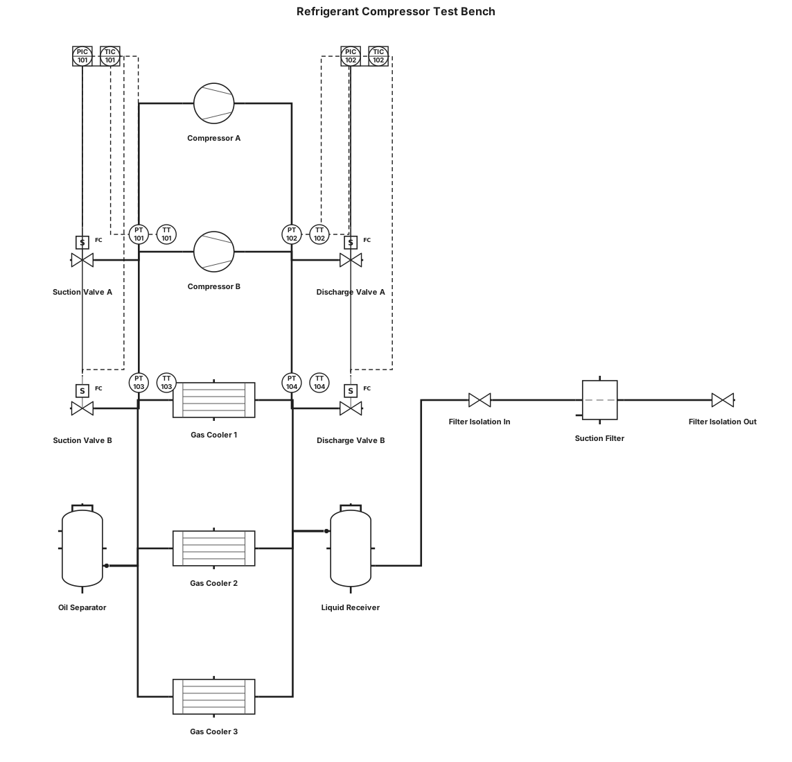
A P&ID for a closed loop refrigerant gas compressors test bench, with two compressors parallel positions. Pressure and temperature sensors at the suction and discharge of every compressor. Electrovalves at every inlet (before sensors) and outlet lines (after sensors) of the compressors. After the discharge line union, and before the cooler, an oil separator vessel. The gas cooler are three in parallel. After coolers, a liquid receiver vessel. After liquid receiver, a filter with manual valves for maintenance.
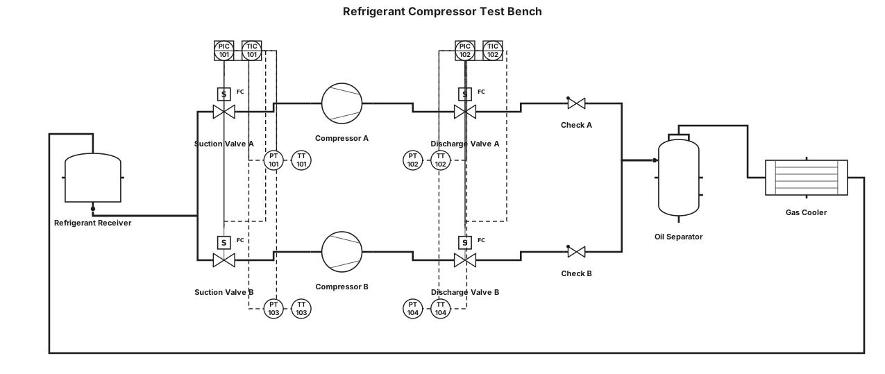
A P&ID for a closed loop refrigerant gas compressors test bench, with two compressors parallel positions. We have pressure and temperature sensors at the suction and discharge of every compressor. Electrovalves at every inlet (before sensors) and outlet lines (after sensors) of the compressors. After the discharge line union, and before the cooler, we have an oil separator vessel.
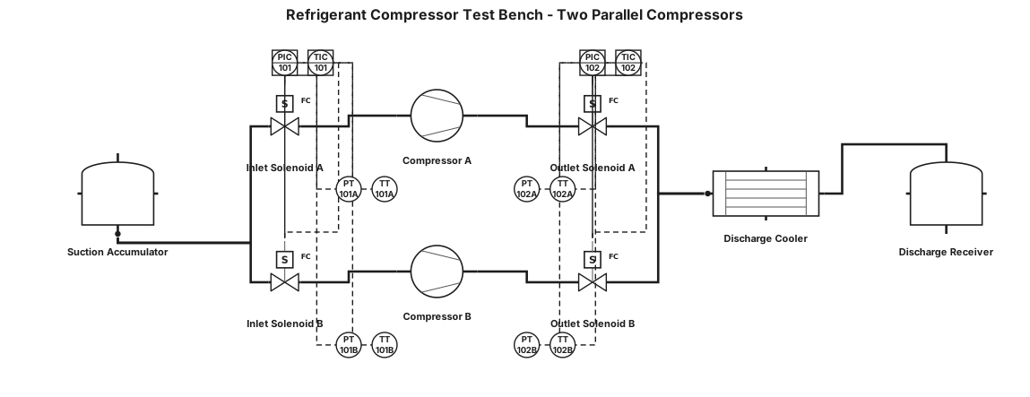
A P&ID for a closed loop refrigerant gas compressors test bench, with two compressors parallel positions. We have pressure and temperature sensors at the suction and discharge of every compressor. Electrovalves at every inlet (before sensors) and outlet lines (after sensors) of the compressors.
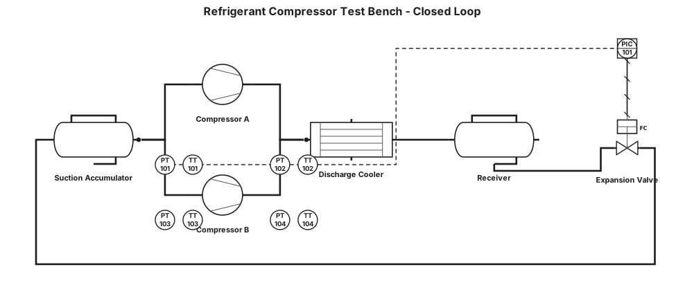
A P&ID for a closed loop refrigerant gas compressors test bench, with two compressors parallel positions. We have pressure and temperature sensors at the suction and discharge of every compressor.
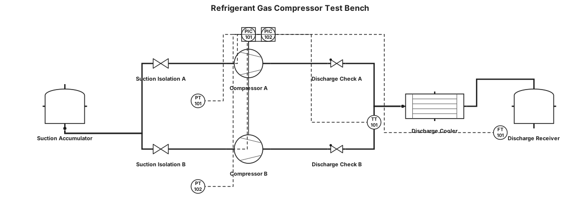
A P&ID for a refrigerant gas compressors test bench, with two compressors parallel positions.
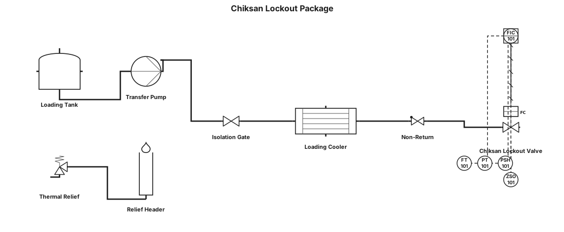
chiksan lockout package

purified water generation system