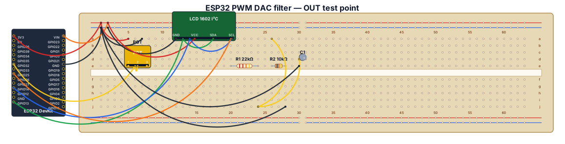
Create a clear Fritzing-style breadboard wiring diagram for a Freenove ESP32 WROVER CAM board (a generic ESP32 DevKit representation is acceptable), a 10k potentiometer, an I2C LCD1602, two resistors, and one polarized electrolytic capacitor. Exact connections: potentiometer outer pins to ESP32 3.3V and GND, center wiper to GPIO32. LCD1602 GND to GND, VCC to 5V, SDA to GPIO13, SCL to GPIO14. Filtered PWM output: GPIO25 connects ONLY to one end of R1 22k ohm; the other end of R1 is the OUT node. From the OUT node connect R2 10k ohm to GND. Also connect C1 10uF electrolytic from OUT to GND, with capacitor positive (+) at OUT and negative (-) at GND. Label OUT as the DUT analog input/test point and connect DUT ground to the common GND rail. Clearly show a common ground rail, resistor values, capacitor polarity, GPIO labels, and emphasize that the DUT must connect to OUT after R1, never directly to GPIO25.
Diagram Examples from Real Visitor Prompts
Browse eligible diagrams shared by FreeDiagram visitors, inspect the exact prompts, and build your own version.
Browse 937 real creationsAll visitor creations
Showing 505–528 of 937. No stock examples or system defaults. Choose a tool, study a real result, then reopen its prompt as your starting point.
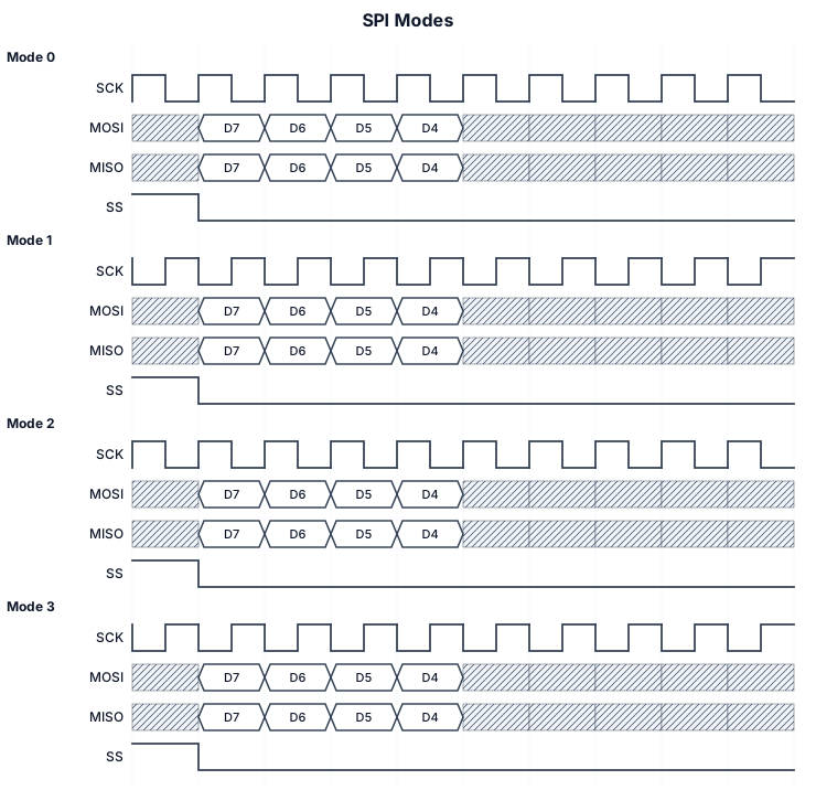
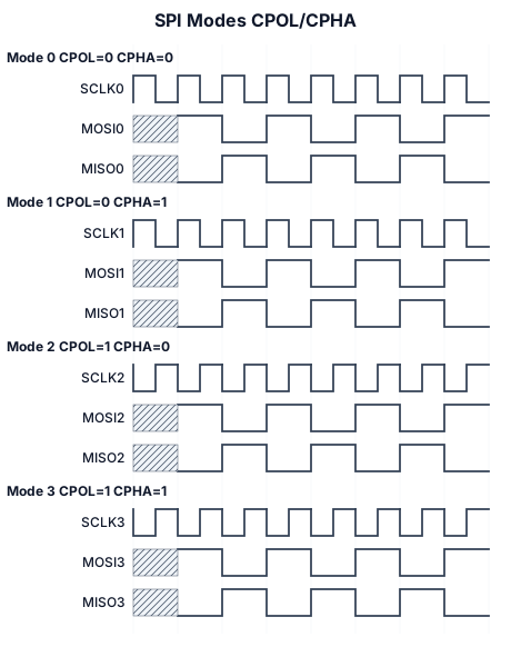
SPI with 4 modes, show time zero with vertical bar
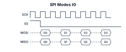
SPI with 4 modes, show t0
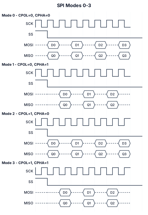
SPI with 4 modes
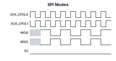
SPI Modes
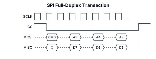
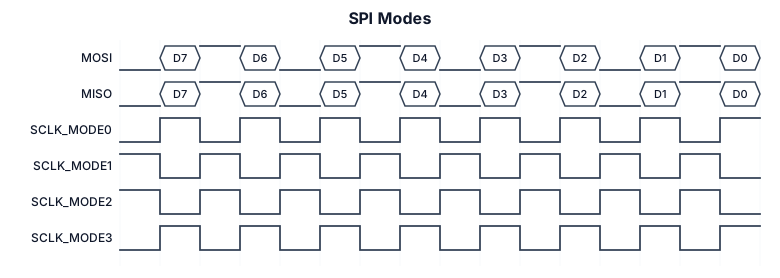
SPI full-duplex transaction with SCLK, MOSI, and MISO signals
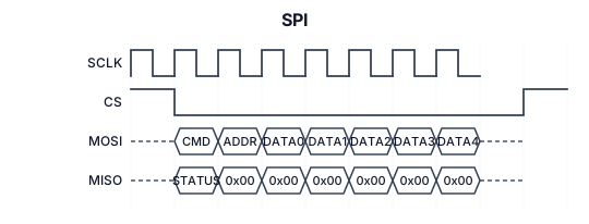
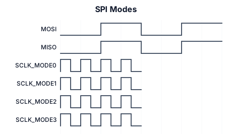
A timing diagram for an SPI Modes: (mosi/miso bit data), sclk (mode 0) cpol=0, cpha=0, sclk (mode 1) cpol=0, cpha=1, sclk (mode 3) cpol=1, cpha=0, sclk (mode 3) cpol=1, cpha=1
A timing diagram for an SPI Modes: (mosi/miso) (bit data), sclk (mode 0) cpol=0, cpha=0, sclk (mode 1) cpol=0, cpha=1, sclk (mode 3) cpol=1, cpha=0, sclk (mode 3) cpol=1, cpha=1
A timing diagram for an SPI Modes: mosi/miso(bit data), sclk (mode 0) cpol=0, cpha=0, sclk (mode 1) cpol=0, cpha=1, sclk (mode 3) cpol=1, cpha=0, sclk (mode 3) cpol=1, cpha=1
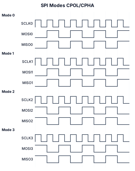
A timing diagram for an SPI Modes: mosi/miso data, sclk (mode 0) cpol=0, cpha=0, sclk (mode 1) cpol=0, cpha=1, sclk (mode 3) cpol=1, cpha=0, sclk (mode 3) cpol=1, cpha=1
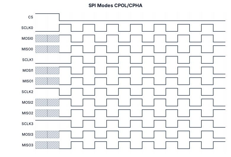
A timing diagram for an SPI Modes: mosi/miso, sclk (mode 0) cpol=0, cpha=0, sclk (mode 1) cpol=0, cpha=1, sclk (mode 3) cpol=1, cpha=0, sclk (mode 3) cpol=1, cpha=1
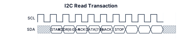
A timing diagram for an I2C read transaction: SCL clock, SDA with START condition, 7-bit address byte, ACK bit, data byte, and STOP condition
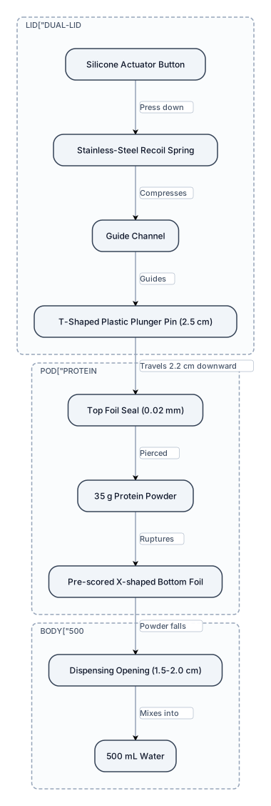
Create a detailed technical cross-section diagram of a 500 mL protein shaker bottle called Pop-Shaker. Show the entire bottle and a 3.0 cm dual-lid assembly. Inside the lid, show a silicone actuator button, stainless-steel recoil spring, guide channel, and a 2.5 cm T-shaped plastic plunger pin. Show the plunger traveling 2.2 cm downward through a sealed 2.0 cm tall protein pod containing 35 g of powder. Show the 0.02 mm top foil being pierced and the pre-scored X-shaped bottom foil being ruptured. Show the powder falling through a 1.5–2.0 cm dispensing opening into the 500 mL water chamber. Label every component and measurement. Use a clean engineering-style cross-section, with arrows showing the direction of movement and powder flow.

Les obligations réglementaires (ONSSA) Au Maroc, l'Office National de Sécurité Sanitaire des Produits Alimentaires (ONSSA) est l'autorité compétente en matière de sécurité sanitaire des aliments. Ses principales exigences applicables à la distribution reposent sur : ● La loi 28-07 relative à la sécurité sanitaire des produits alimentaires et ses textes d'application. ● L'obligation de traçabilité à toutes les étapes de la chaîne (« un pas en amont, un pas en aval »). ● L'obligation de retrait/rappel en cas de non-conformité identifiée. ● Le respect des températures réglementaires de conservation et de transport des denrées périssables. ● La tenue de registres et documents justifiant la maîtrise sanitaire (plans de nettoyage, relevés de températures, cartes sanitaires du personnel, etc.).
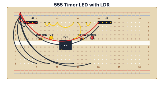
A breadboard wiring diagram with a LDR, 104 capacitor, chip 555 , a led and two jumpers
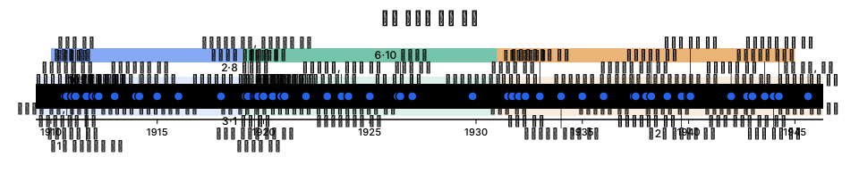
일제 강점기의 모든 사건(200가지)
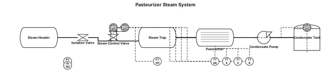
Pasteurizer steam system: Steam header → isolation valve → steam control valve → steam trap → condensate return line. Pasteurizer has temperature transmitters TT4A, TT4, TT5 and TT6. Condensate is collected and returned by a condensate pump. Show pressure, temperature and flow instrumentation.
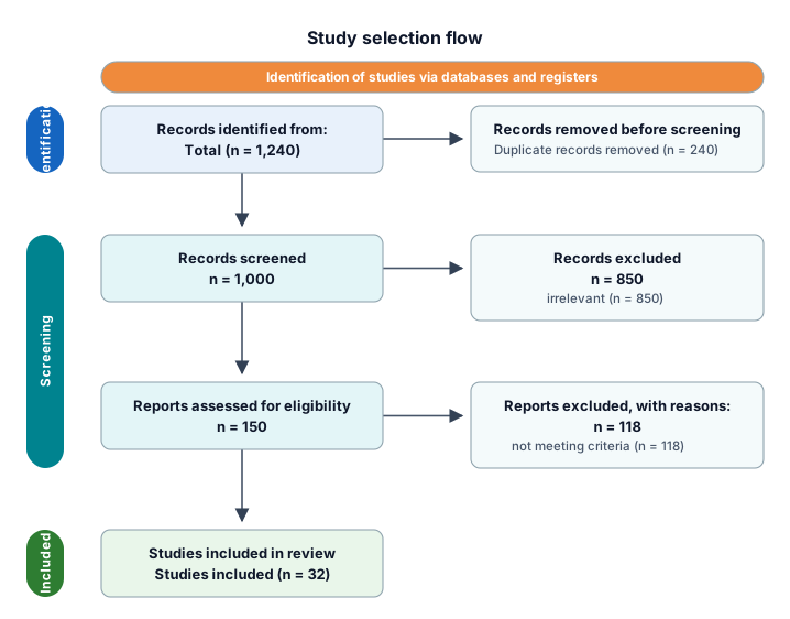
A PRISMA study-selection flow from 1,240 identified records through deduplication, screening, eligibility, and 32 included studies

ONGOING SUPERVISION & PUBLIC PROJECTS │ ├── 01 PRE-AWARD / PRE-CONSTRUCTION │ │ │ ├── Tender Documents │ │ ├── Tender Terms & Conditions │ │ ├── Drawings │ │ ├── Specifications │ │ ├── BOQ │ │ └── Appendices │ │ │ ├── Technical & Financial Proposal │ ├── Clarifications & Negotiations │ ├── Award / LOA │ │ │ ├── Agreements & Contract │ │ ├── Contract Agreement │ │ ├── Amendments / Addenda │ │ └── Contractual Documents │ │ │ ├── Bonds & Guarantees │ │ ├── Performance Bond │ │ ├── Advance Payment Guarantee │ │ └── Other Guarantees │ │ │ ├── Advance Payment │ │ ├── Advance Payment Request │ │ └── Advance Payment Documents │ │ │ ├── Programme / Schedule │ │ ├── Baseline Programme │ │ └── Detailed Work Schedule │ │ │ └── Mobilization / Commencement │ ├── Commencement Date │ ├── Project Manager / Organization Chart │ └── Mobilization Documents │ ├── 02 CONSTRUCTION / EXECUTION │ │ │ ├── Contract Administration │ ├── Technical / Design │ ├── Materials │ ├── Inspection & Testing │ ├── Progress & Reports │ ├── Meetings │ ├── Commercial │ ├── HSE / Environmental │ └── Defects / Non-Conformance │ └── 03 CLOSE-OUT │ ├── Completion / Final Inspection ├── Taking Over ├── Outstanding Works ├── Defects Liability ├── Final Documentation └── Final Commercial Close-Out
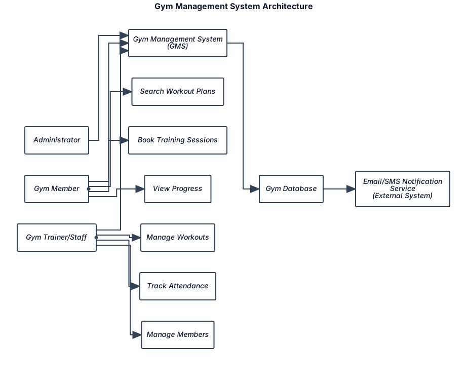
Create a clean system architecture diagram for a Gym Management System. Put Administrator at the top and connect it to the central Gym Management System (GMS). On the left, add Gym Member connected to GMS with: Search Workout Plans, Book Training Sessions, View Progress. On the right, add Gym Trainer/Staff connected to GMS with: Manage Workouts, Track Attendance, Manage Members. Below GMS, add Gym Database. Below the database, add Email/SMS Notification Service (External System). Use rounded rectangular boxes, arrows, a professional academic style, and arrange it similar to a library management system architecture diagram.
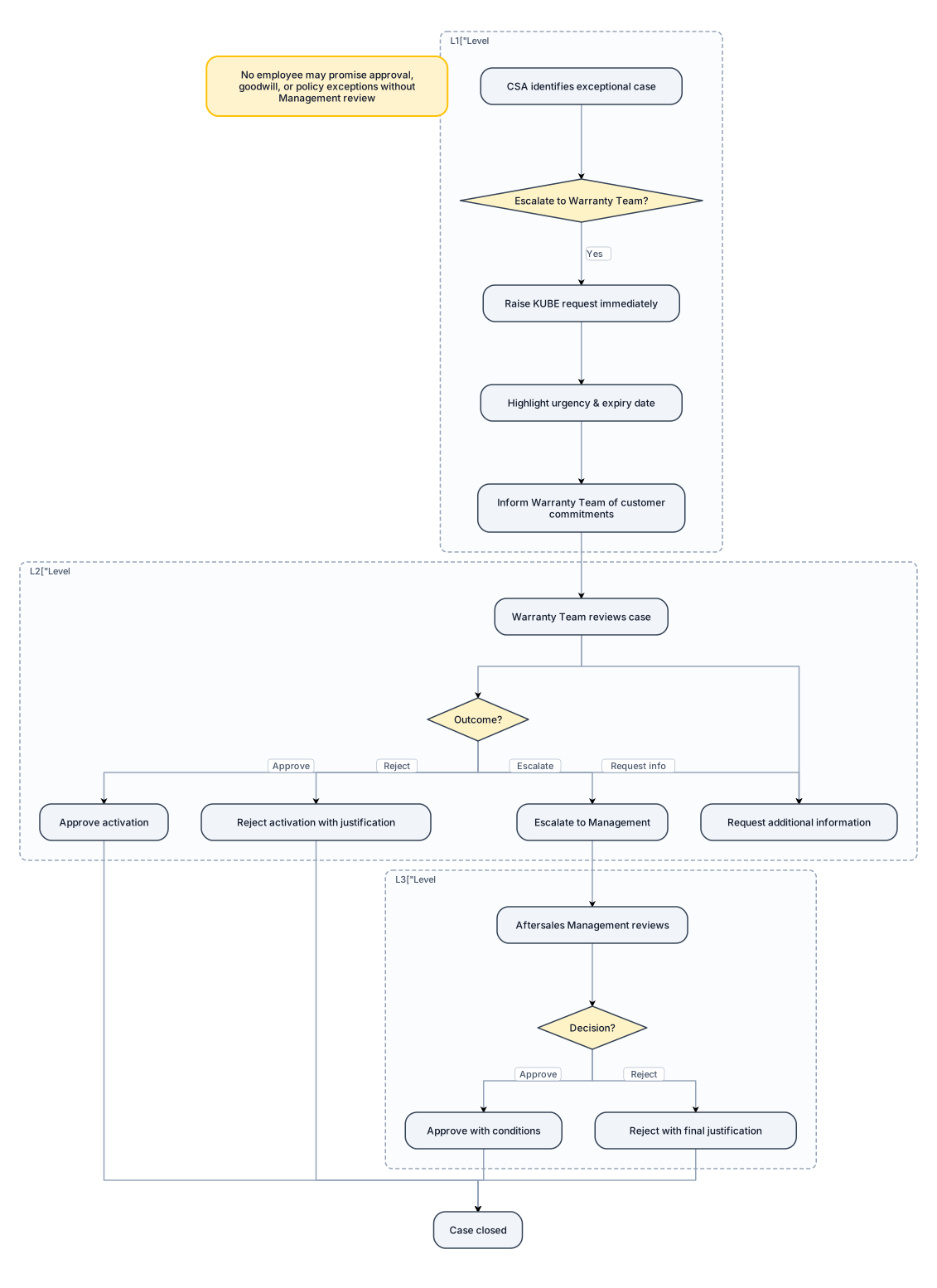
6. Escalation Procedure To avoid warranty expiry, activation delays, customer disputes, and business risks, all exceptional cases must be escalated promptly. Level 1: CSA Escalation The CSA must immediately escalate to the Warranty Team when: • Warranty expiry is imminent and activation may not be completed before the expiry date. • Customer disputes the "No Grace Period" policy. • Customer requests an exception to standard PAW requirements. • The CSA is uncertain whether the vehicle qualifies for Extension or Standalone Warranty. • Required documentation cannot be obtained. • Any non-standard or unusual case arises. Action Required: • Raise a KUBE request immediately. • Highlight the urgency and expiry date. • Inform the Warranty Team of any customer commitments already communicated. Level 2: Warranty Team Review The Warranty Team shall review: • Eligibility concerns. • Missing documentation. • Standalone Warranty prerequisites. • Potential policy exceptions. • Customer disputes relating to activation requirements. Outcome: • Approve activation. • Request additional information. • Reject activation with justification. • Escalate to Management where required. Level 3: Management Escalation The Warranty Team shall escalate to Aftersales Management when: • A customer requests a policy exception. • A potential financial, legal, or reputational risk exists. • A complaint involves warranty coverage during an expired period. • Internal procedural non-compliance is identified. • The case falls outside the scope of this SOP. Important: No employee may promise approval, goodwill support, or policy exceptions to a customer without Management review and approval.
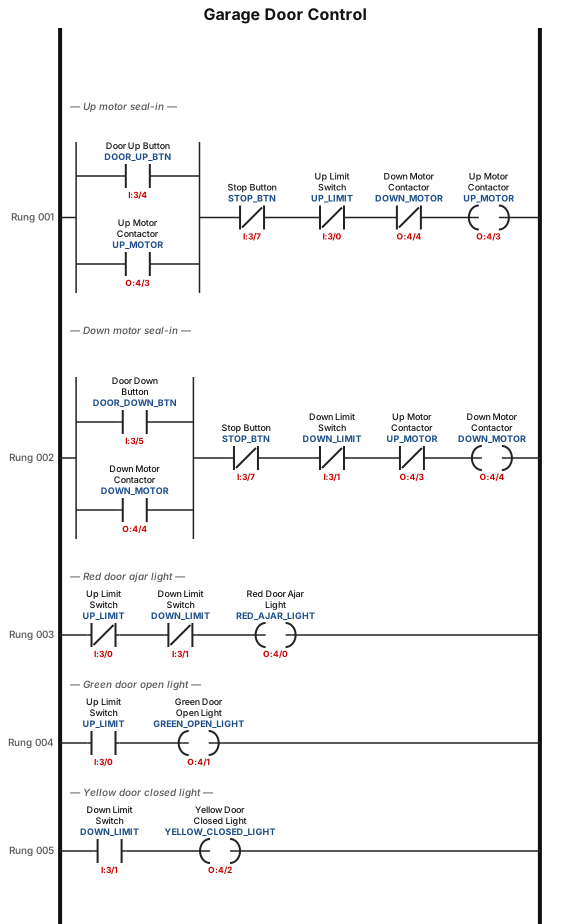
A motorized overhead garage door is to be operated automatically to preset open and closed positions. The field devices include one of each of the following: • Reversing motor contactor for the up and down directions. • Normally open down limit switch to sense when the door is fully closed. • Normally open-held closed up-limit switch to sense when the door is fully opened. • Normally open door up button for the up direction. • Normally open door down button for the down direction. • Normally closed door stop button for stopping the door. • Red door ajar light to signal when the door is partially open. • Green door open light to signal when the door is fully open. • Yellow door closed light to signal when the door is fully closed. The sequence of operation requires that: • When the up button is pushed, the up-motor contactor energizes and the door travels upward until the up-limit switch is actuated. • When the down button is pushed, the down motor contactor energizes and the door travels down until the down limit switch is actuated. • When the stop button is pushed, the motor stops. The motor must be stopped before it can change direction Tag Device Type Function I:3/0 Up limit NO-held closed Detects when door is fully open I:3/1 Down limit NO Detects when door is fully closed I:3/4 Door up button NO Command to raise door I:3/5 Door down button NO Command to lower door I:3/7 Stop door button NC Stops motor immediately Tag Device Function O:4/0 Red light Door ajar (neither limit made) O:4/1 Green light Door fully open O:4/2 Yellow light Door fully closed O:4/3 Up motor contactor Energizes motor upward O:4/4 Down motor contactor Energizes motor downward
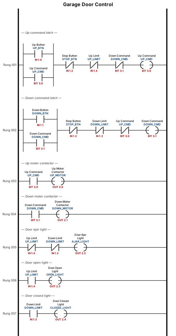
A motorized overhead garage door is to be operated automatically to preset open and closed positions. The field devices include one of each of the following: • Reversing motor contactor for the up and down directions. • Normally open down limit switch to sense when the door is fully closed. • Normally open-held closed up-limit switch to sense when the door is fully opened. • Normally open door up button for the up direction. • Normally open door down button for the down direction. • Normally closed door stop button for stopping the door. • Red door ajar light to signal when the door is partially open. • Green door open light to signal when the door is fully open. • Yellow door closed light to signal when the door is fully closed. The sequence of operation requires that: • When the up button is pushed, the up-motor contactor energizes and the door travels upward until the up-limit switch is actuated. • When the down button is pushed, the down motor contactor energizes and the door travels down until the down limit switch is actuated. • When the stop button is pushed, the motor stops. The motor must be stopped before it can change direction.
Focused examples and prompt ideas
Start with the complete visitor wall above, then use these focused collections when you want a narrower subject and more prompt context.
The first curated collection is being prepared.