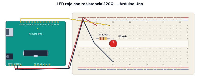
Crea un diagrama estilo Fritzing con un Arduino Uno conectado a un protoboard, un LED rojo y una resistencia de 220 ohmios. Muestra todos los cables de colores, las conexiones exactas a los pines y la conexión a GND. Quiero usar el dibujo para construir el circuito real.
NODE ARCHIVE · REAL DIAGRAM BRIEFS
Diagram Examples from Real Visitor Prompts
Browse eligible diagrams shared by FreeDiagram visitors, inspect the exact prompts, and build your own version.
Browse 3278 real creationsCOMMUNITY OUTPUTS · EXACT PROMPTS
All visitor creations
Showing 649–672 of 3278. No stock examples or system defaults. Choose a tool, study a real result, then reopen its prompt as your starting point.
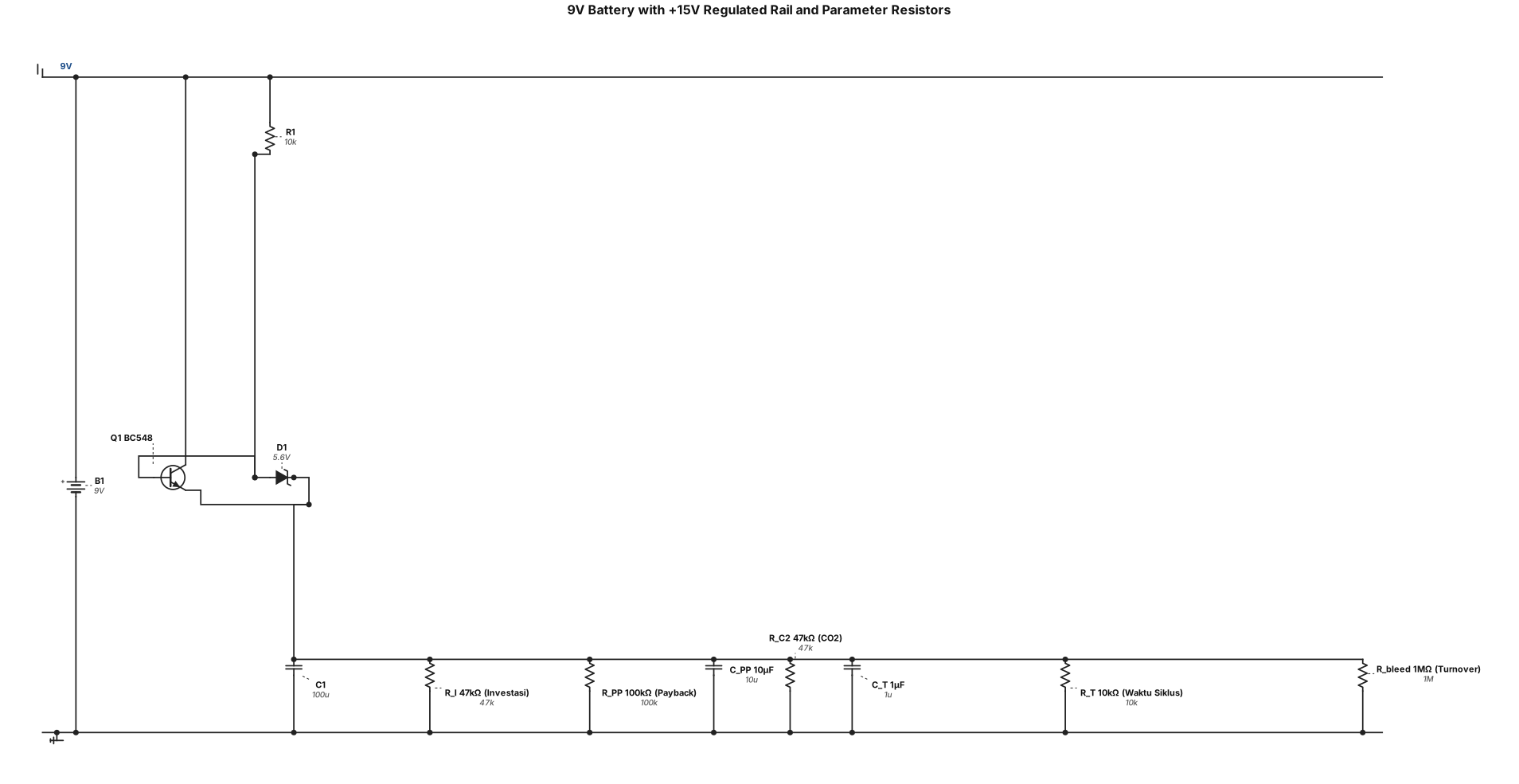
Analog circuit: a 9V battery as main power supply. +15V rail derived through a BC548 regulator (emitter follower). Fifteen fixed resistors representing internal parameters: R_I=47kΩ (Investasi), R_PP=100kΩ with C_PP=10μF (Payback), R_C2=47kΩ (CO2), R_T=10kΩ with C_T=1μF (Waktu Siklus), R_bleed=1MΩ (Turnover). Each labeled with parameter name and value. All connected to +15V rail and ground. Label clearly.
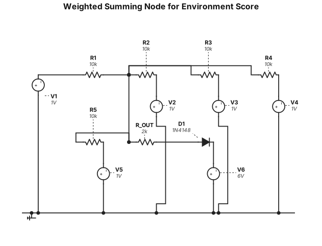
Analog circuit: a weighted summing node for environment score. Five input voltages (V4_Limbah, V_C2_CO2, V_Lk_TenagaLokal, V_D_JarakAir, V_Rek_Reklamasi) each connected through a 10kΩ resistor to a common summing node. The summing node connected through R_OUT=2kΩ to output V_ENV. A 1N4148 diode from V_ENV to +6V reference (threshold clamp). Label all resistors 10kΩ, R_OUT=2kΩ, diode 1N4148.
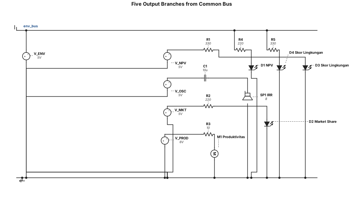
Analog circuit: five output branches from a common bus. Branch 1: V_NPV through R=330Ω to a red LED (anode to V_NPV, cathode to ground), labeled "NPV". Branch 2: oscillator output through C=10μF coupling to an 8Ω speaker, labeled "IRR". Branch 3: V_MKT through R=220Ω to a green LED, labeled "Market Share". Branch 4: V_PROD through R=10Ω to a 6V DC motor (labeled "Produktivitas"). Branch 5: V_ENV through R1=220Ω to a blue LED and R2=330Ω to an orange LED (both cathodes to ground), labeled "Skor Lingkungan". Label all components.
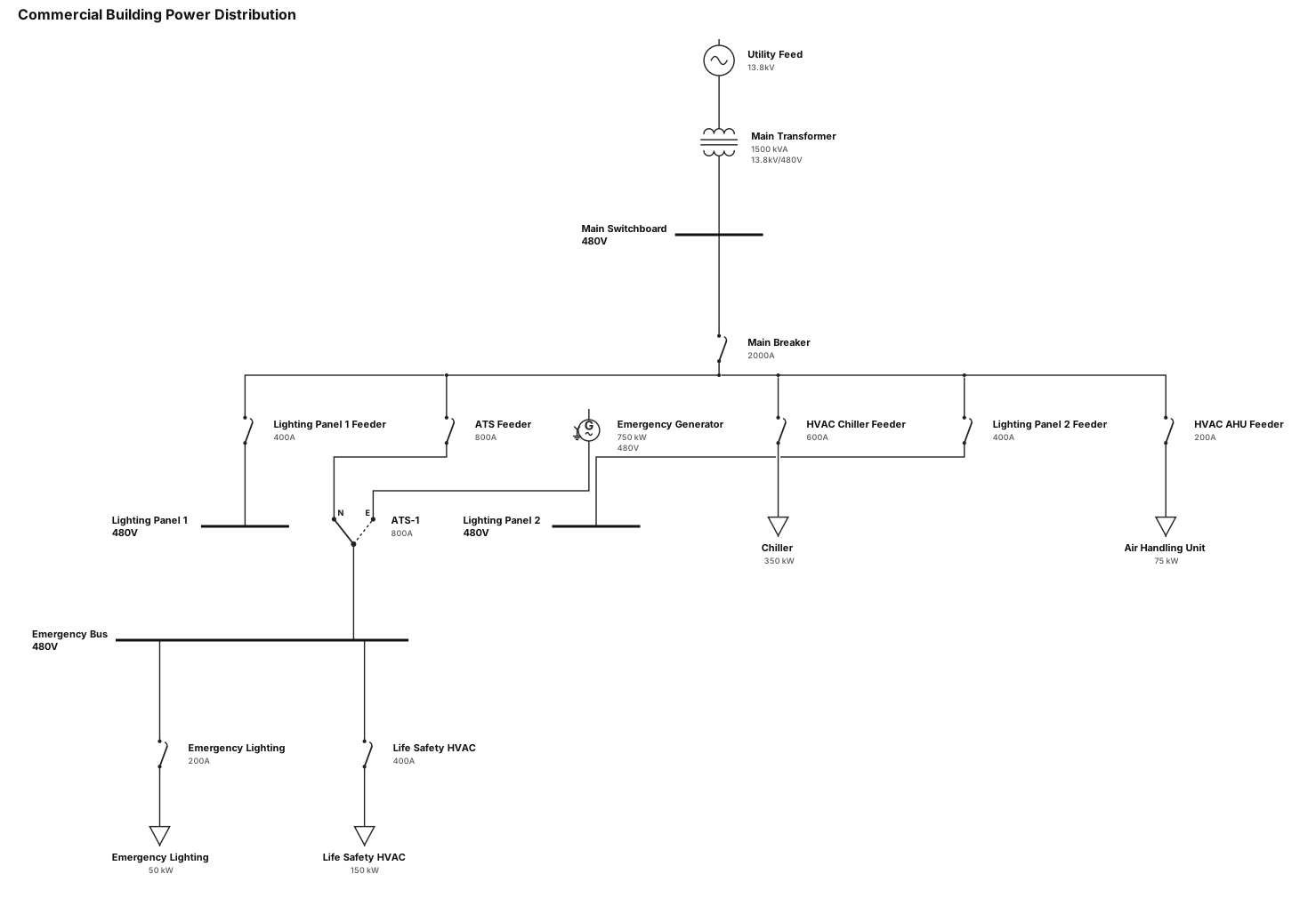
A single-line diagram for a commercial building: utility feed through a main transformer to a 480V switchboard, then to lighting panels, HVAC equipment, and an emergency generator with ATS
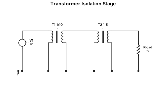
Analog circuit: a transformer with primary winding N1=100 turns and secondary winding N2=1000 turns (1:10 ratio). Primary connected to V_AMP input. Secondary output labeled V_ISOLATED. A second transformer with 1:K ratio (K variable, shown as 1:5 turns ratio as example). Label both transformers with turns ratio. Input labeled "V_AMP", output labeled "V_ISOLATED = V_AMP × K".
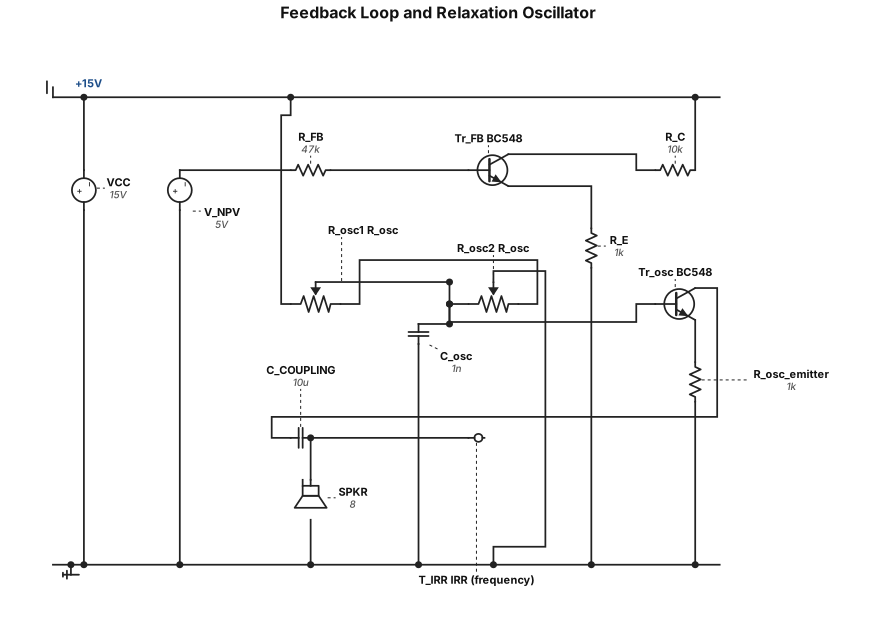
Analog circuit: a feedback loop and relaxation oscillator. V_NPV from previous stage connected through R_FB=47kΩ to the base of a BC548 NPN transistor (Tr_FB). Tr_FB emitter through R_E=1kΩ to ground, collector to +15V. A relaxation oscillator circuit: second BC548 transistor with R_osc=10kΩ (potentiometer) and C_osc=1nF forming a timing loop. Oscillator output coupled through C_COUPLING=10μF to an 8Ω speaker (SPKR). Label all components with values. Output labeled "IRR (frequency)".
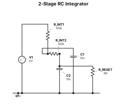
Analog circuit: a 2-stage RC integrator. Input V_DRAIN from previous stage connected through R_INT1=100kΩ to a node with C1=10μF to ground (first integrator stage). First stage output connected through R_INT2=100kΩ to a second node with C2=10μF to ground (second integrator stage). A reset resistor R_RESET=1MΩ from second stage output to ground. Output labeled V_NPV at second stage. Label all components with values.
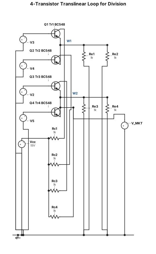
Analog circuit: a 4-transistor translinear loop for division. Four BC548 NPN transistors (Tr1, Tr2, Tr3, Tr4) arranged in a 2x2 loop. Tr1 and Tr2 emitters tied together, Tr3 and Tr4 emitters tied together. Tr1 base receives input V3, Tr2 base receives input V4, Tr3 base receives input V2, Tr4 base receives input V5. Each collector has a 1kΩ resistor to +15V. Each emitter has a 1kΩ resistor to ground. Output V_MKT taken at Tr4 collector. Label all transistors BC548, all resistors 1kΩ.
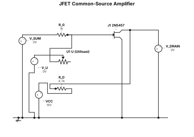
Analog circuit: a JFET 2N5457 in common-source configuration. Gate connected through 1kΩ resistor (R_G) to input V_SUM. A 10kΩ potentiometer labeled "U (Utilisasi)" provides gate bias voltage V_U. Drain connected through 4.7kΩ resistor (R_D) to +15V supply. Source connected to ground. Output V_DRAIN taken at drain node. Label all components: JFET type 2N5457, R_G=1kΩ, R_D=4.7kΩ, pot U=10kΩ.
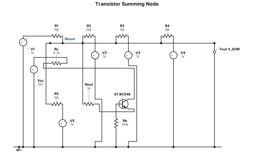
Analog circuit: a summing node (virtual ground) using an inverting op-amp configuration replaced by a single BC548 NPN transistor as current sink. Five input voltages V1 through V5 each connected through a resistor (R1=10kΩ, R2=20kΩ, R3=15kΩ, R4=10kΩ, R5=10kΩ) to a common node. The common node connects through R_OUT=5kΩ to a BC548 emitter. Collector to +15V through 4.7kΩ. Base biased through 100kΩ to ground. Output labeled V_SUM at the common node. Label all resistors with values.
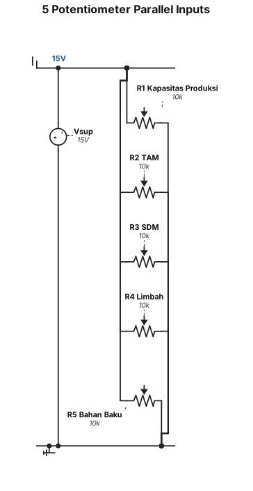
Analog circuit: 5 potentiometers (10kΩ each) connected in parallel to a +15V supply, each wiper output labeled V1 through V5. V1 labeled "Kapasitas Produksi", V2 labeled "TAM", V3 labeled "SDM", V4 labeled "Limbah", V5 labeled "Bahan Baku". All bottom terminals connected to ground. Clean schematic with component values labeled.
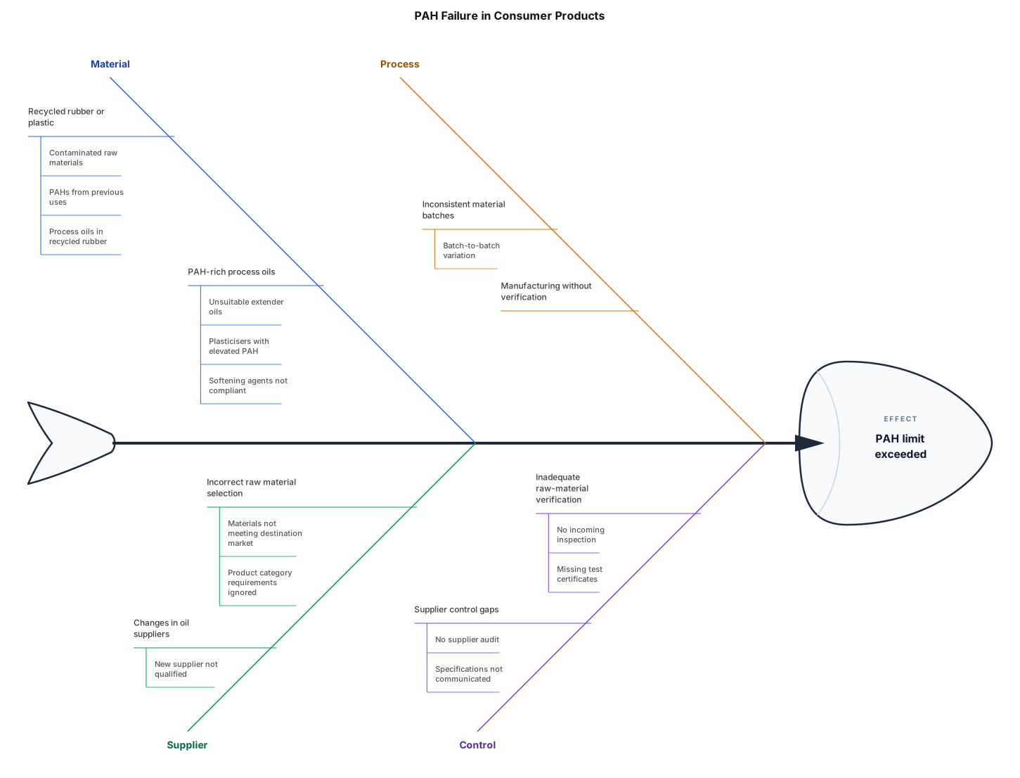
Main reasons for PAH failure in consumer products 1. Recycled rubber or plastic-Recycled materials may contain PAHs originating from contaminated raw materials or previous uses. Some recycled rubber compounds can contain PAHs from process oils. 2. Use of PAH-rich process oils- Certain extender oils, plasticisers and softening agents used in rubber manufacturing can contain elevated PAH concentrations if unsuitable grades are selected. 3. Incorrect raw material selection- Suppliers may use raw materials that do not meet the PAH requirements of the destination market or product category. 4. Manufacturing and supplier control issues- Inadequate raw-material verification, changes in oil suppliers or inconsistent material batches can lead to PAH concentrations exceeding the limit.
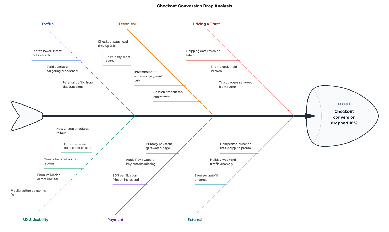
A fishbone diagram analysing why our checkout conversion dropped 18% last week
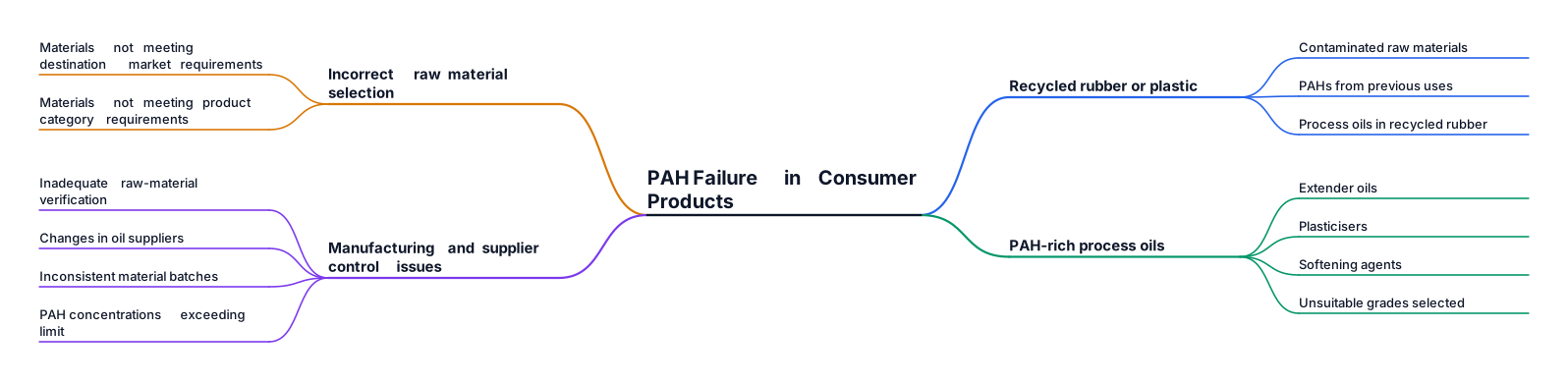
Main reasons for PAH failure in consumer products 1. Recycled rubber or plastic-Recycled materials may contain PAHs originating from contaminated raw materials or previous uses. Some recycled rubber compounds can contain PAHs from process oils. 2. Use of PAH-rich process oils- Certain extender oils, plasticisers and softening agents used in rubber manufacturing can contain elevated PAH concentrations if unsuitable grades are selected. 3. Incorrect raw material selection- Suppliers may use raw materials that do not meet the PAH requirements of the destination market or product category. 4. Manufacturing and supplier control issues- Inadequate raw-material verification, changes in oil suppliers or inconsistent material batches can lead to PAH concentrations exceeding the limit.
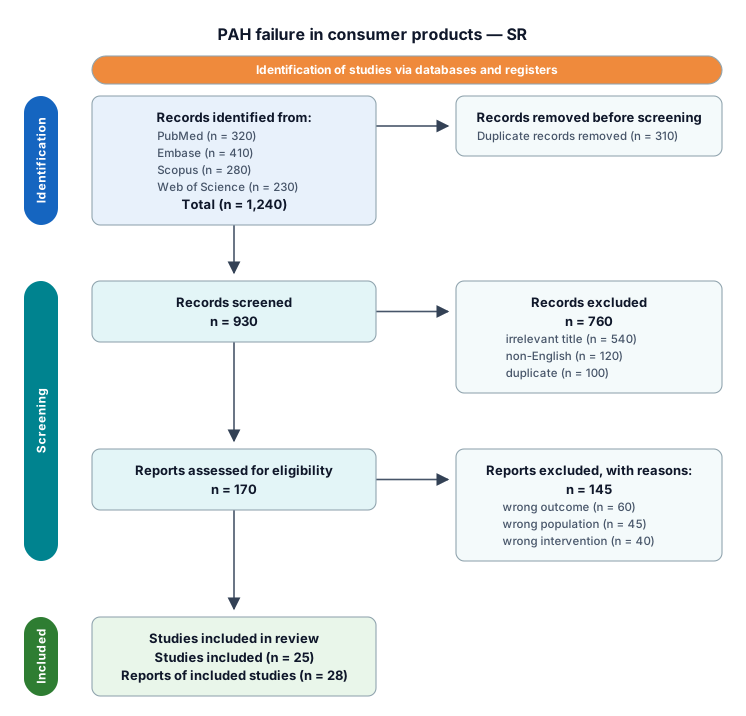
Main reasons for PAH failure in consumer products 1. Recycled rubber or plastic-Recycled materials may contain PAHs originating from contaminated raw materials or previous uses. Some recycled rubber compounds can contain PAHs from process oils. 2. Use of PAH-rich process oils- Certain extender oils, plasticisers and softening agents used in rubber manufacturing can contain elevated PAH concentrations if unsuitable grades are selected. 3. Incorrect raw material selection- Suppliers may use raw materials that do not meet the PAH requirements of the destination market or product category. 4. Manufacturing and supplier control issues- Inadequate raw-material verification, changes in oil suppliers or inconsistent material batches can lead to PAH concentrations exceeding the limit.
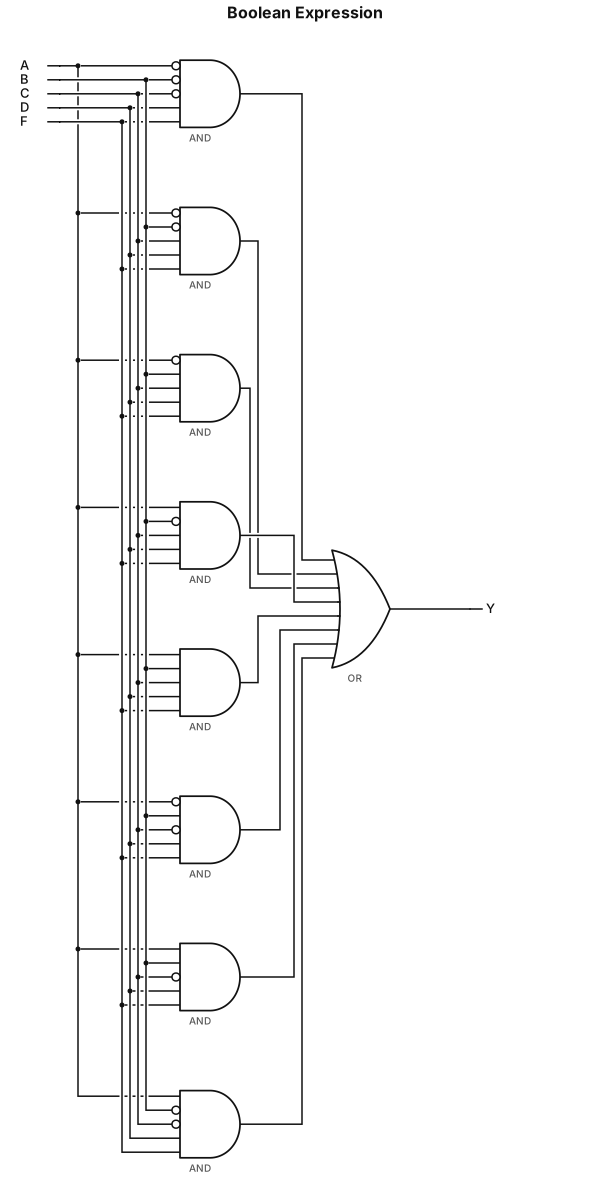
A′B′C′DF+A′B′CDF+A′BCDF+AB′CDF+ABCDF+A′BC′DF+ABC′DF+AB′C′DF
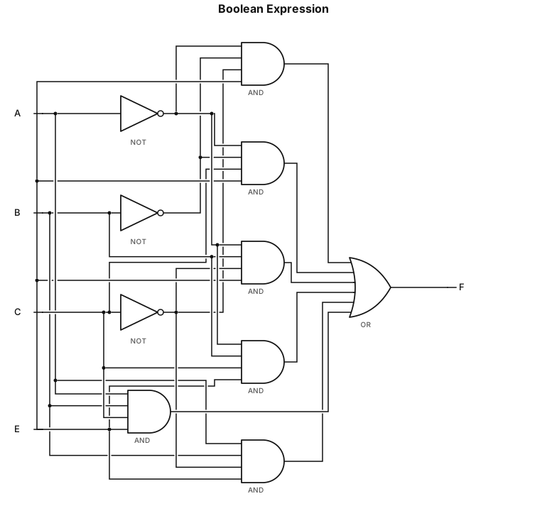
A′B′C′E+A′B′CE+A′BC′E+A′BCE+ABC′E+ABCE
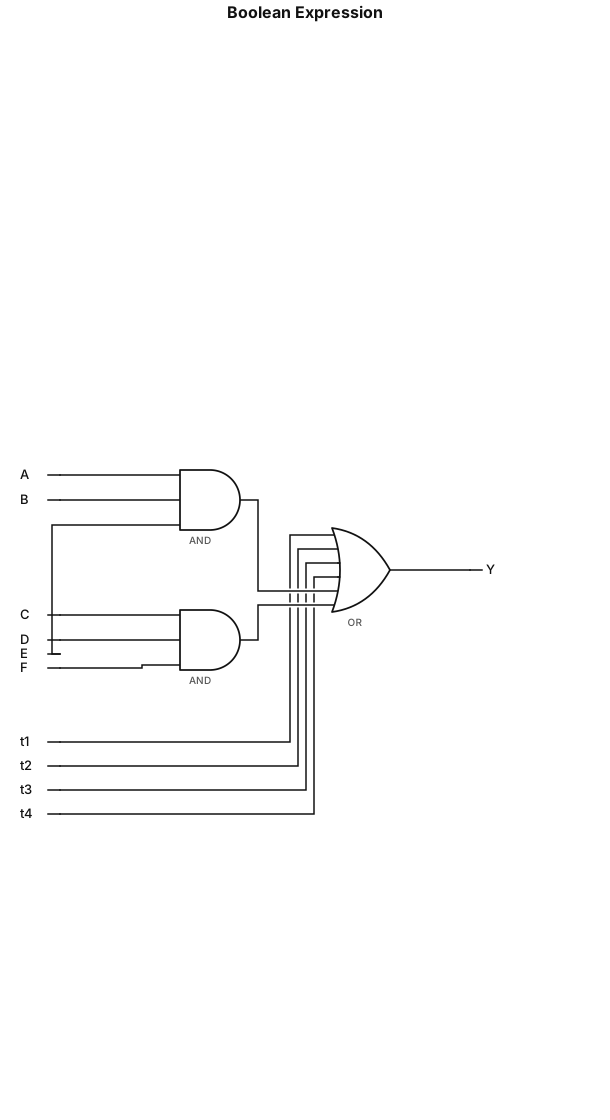
Y=A′BC+AB′D+AC′E+BCD′+ABE+CDF
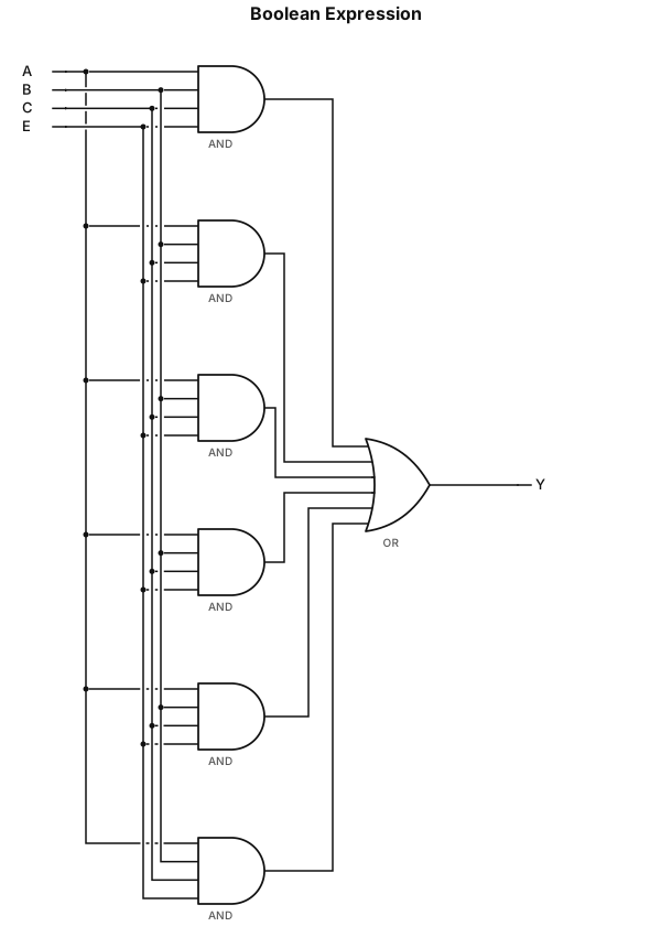
A′B′C′E+A′B′CE+A′BCE+ABCE+ABC′E+A′BC′E
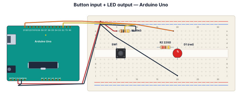
A breadboard wiring diagram for an Arduino Uno reading a button press and lighting an LED: button with pull-down resistor on D2, LED with 220-ohm resistor on D13

Create a Single-line diagram: i Have two AC power sources. One RAW power and one more is UPS Power. RAW power source will be connected to AC 25AMPS MCB. From there it is distributed to a 3 Sockets 10A Junction box and a Mitsubishi Fx5u CPU. The 10A 3 Sockets will be connected to 3 Industrial PC with input 230V AC and 7.5Amps. Next Comes the UPS Power UPS power source will be connected to AC 25AMPS MCB. Here there are multiple Distibutions. the power is first distributed to a single socket 6A. where we will connect TV with 230VAC, 1Amps input. Next distibuted to two sockets of 6A. Where the first socket is connected to Monitor (230V AC 1A). second socket is connected to HUB(230VAC 1A) Next the power is connected to two MCB with 6A each. Now from each MCB it is connected to four SMPS which has input of 230VAC 3A and provides output of 24vDC. from each smps we will connect to two relays(24V DC input) the relay input will connected from PLC and each relay has two common and two NO and two NC. Common will be connected from smps and from each NO we will connect one light with an input of 24V DC. Like this we will connect 16 lights using 8 relays in which every two relays are connected to one smps. Next distribution is we will connect 8 Exhaust Fans which needs input power of 230VAC 2A combinely for all exhaust fans. I want to add contractor details project details. Client details
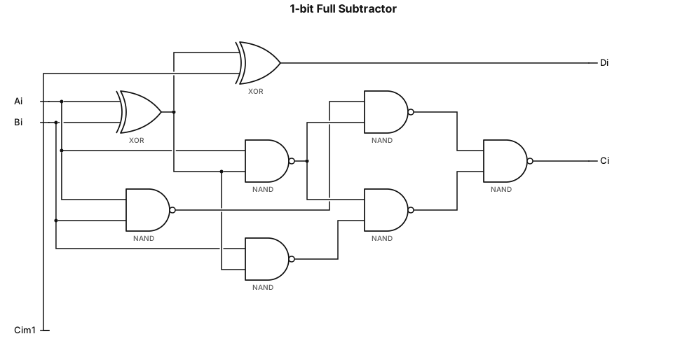
Draw digital logic circuit for 1-bit full subtractor. Inputs: Ai, Bi, C_{i-1}. Output: Di, Ci. Di = Ai xor Bi xor C_{i-1}, use two 2-input XOR gates(74LS86). Ci = NAND combination, use multiple 2-input NAND gates(74LS00). Standard IEEE logic symbols, clean diagram for lab report.
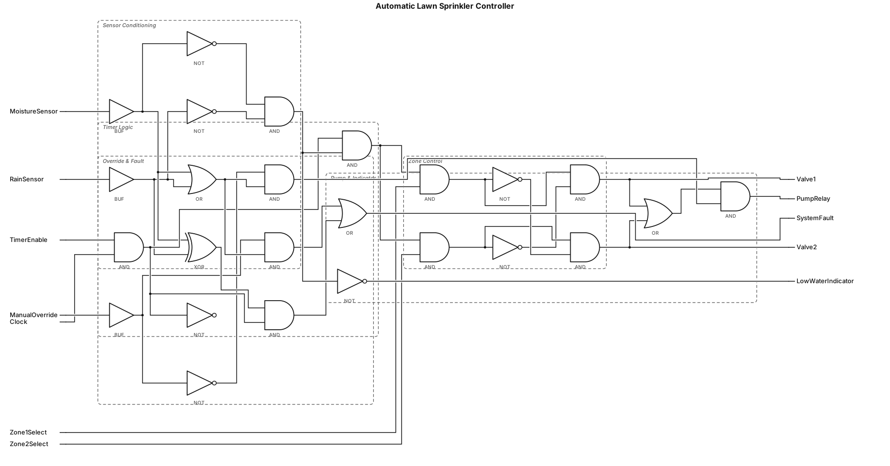
make a logic circuit consisting of 20 logic gates on automatic lawn sprinkler controller.