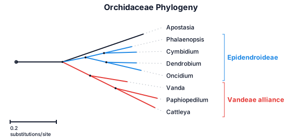
Phalaenopsis, cymbidium, dendrobiu, oncidium, vanda, paphiopedilum and cattleya within the orchidaceae family with apostasia as outlier
NODE ARCHIVE · REAL DIAGRAM BRIEFS
Diagram Examples from Real Visitor Prompts
Browse eligible diagrams shared by FreeDiagram visitors, inspect the exact prompts, and build your own version.
Browse 3279 real creationsCOMMUNITY OUTPUTS · EXACT PROMPTS
All visitor creations
Showing 769–792 of 3279. No stock examples or system defaults. Choose a tool, study a real result, then reopen its prompt as your starting point.
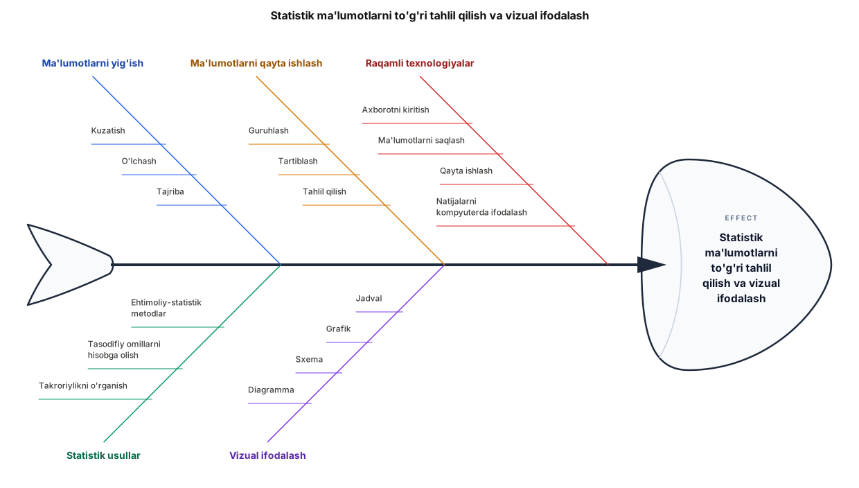
MA’LUMOTLARNI YIG‘ISH STATISTIK USULLAR • Kuzatish • Ehtimoliy-statistik metodlar • O‘lchash • Tasodifiy omillarni hisobga olish • Tajriba • Takroriylikni o‘rganish \ / \ / ===============\==================================/======== \ / \ / > STATISTIK MA’LUMOTLARNI =======> / TO‘G‘RI TAHLIL QILISH VA / VIZUAL IFODALASH ===============/==================================\======== / \ / \ MA’LUMOTLARNI QAYTA ISHLASH VIZUAL IFODALASH • Guruhlash • Jadval • Tartiblash • Grafik • Tahlil qilish • Sxema • Diagramma \ / \ / RAQAMLI TEXNOLOGIYALAR • Axborotni kiritish • Ma’lumotlarni saqlash • Qayta ishlash • Natijalarni kompyuterda ifodalash
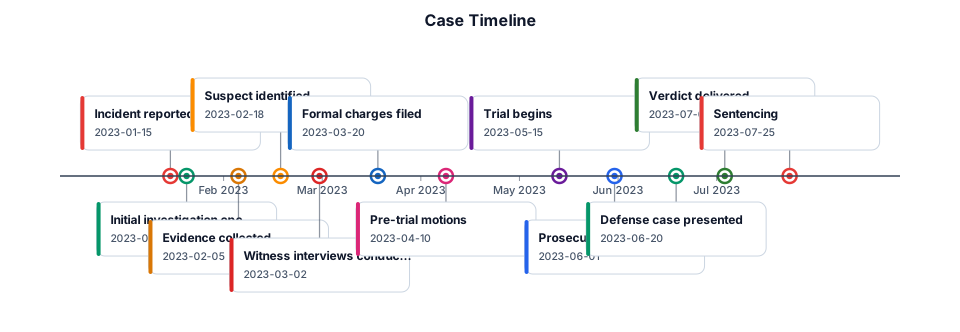
Case timelline
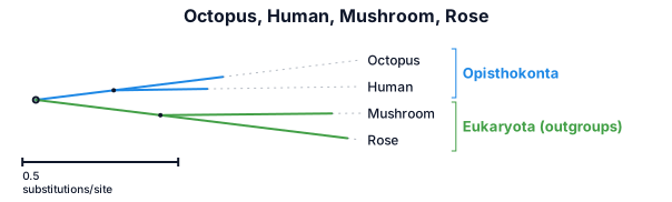
A phylogenetic tree: octopus, human, mushroom, rose
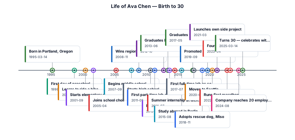
create timeline for fictional character starting from birth to the age of 30
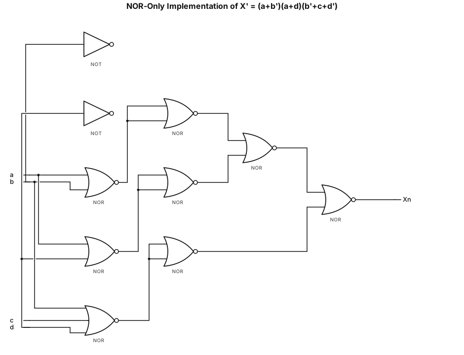
make me a Nor only gate diagram for X'=(a+b')(a+d)(b'+c+d')
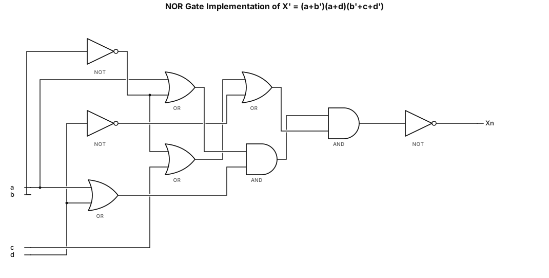
make me a Nor gate diagram for X'=(a+b')(a+d)(b'+c+d')
Create a logic gate circuit diagram for the expression: Output = (NOT A AND B AND NOT C) OR (C AND D AND (NOT A OR NOT B)). Use standard logic gate symbols with input lines for A, B, C, and D, and use NOT gates for the inverted inputs. Combine the terms using AND gates and OR gates to produce the final output.
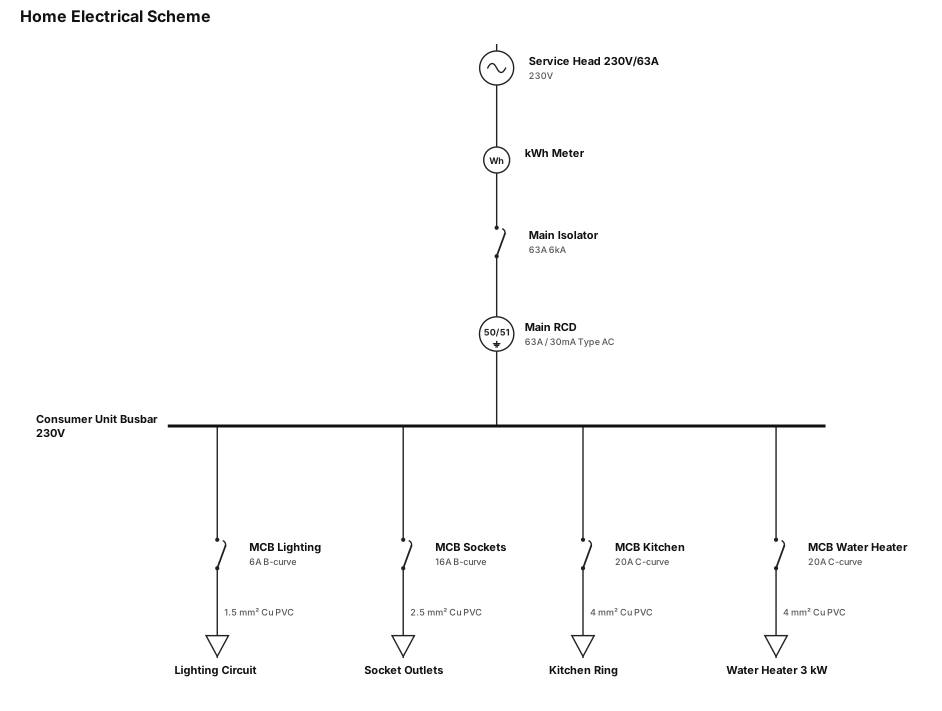
Home scheme
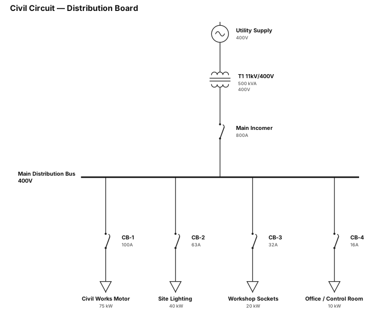
Civil circuit
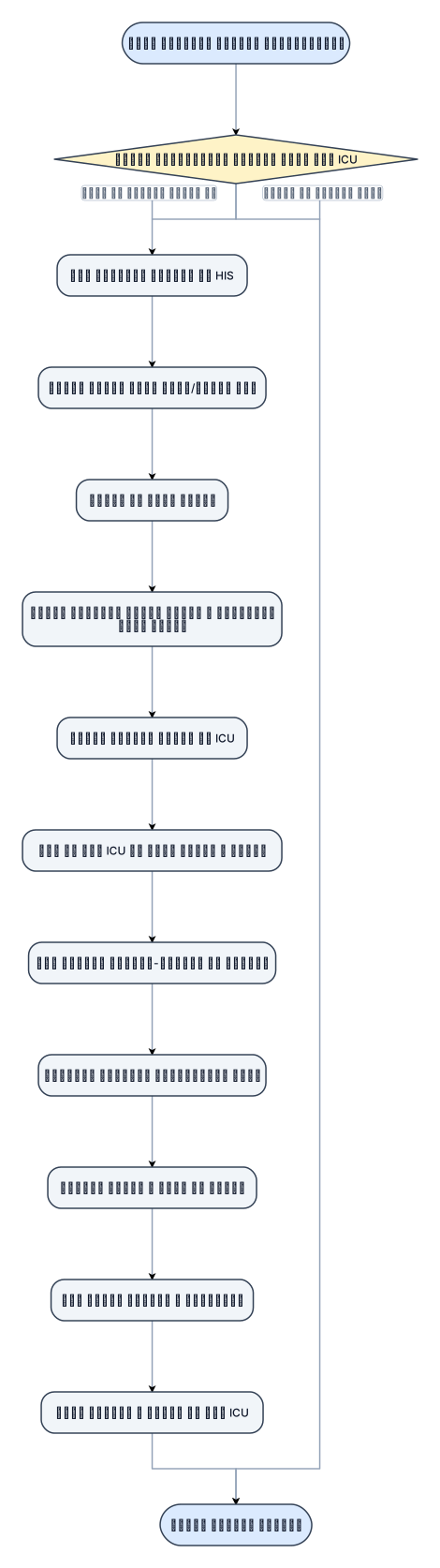
فرآیند انجام مشاوره غیراورژانسی در بخشicu
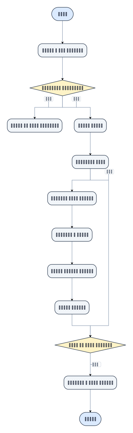
فرایند مشاوره غیر اورژانسی
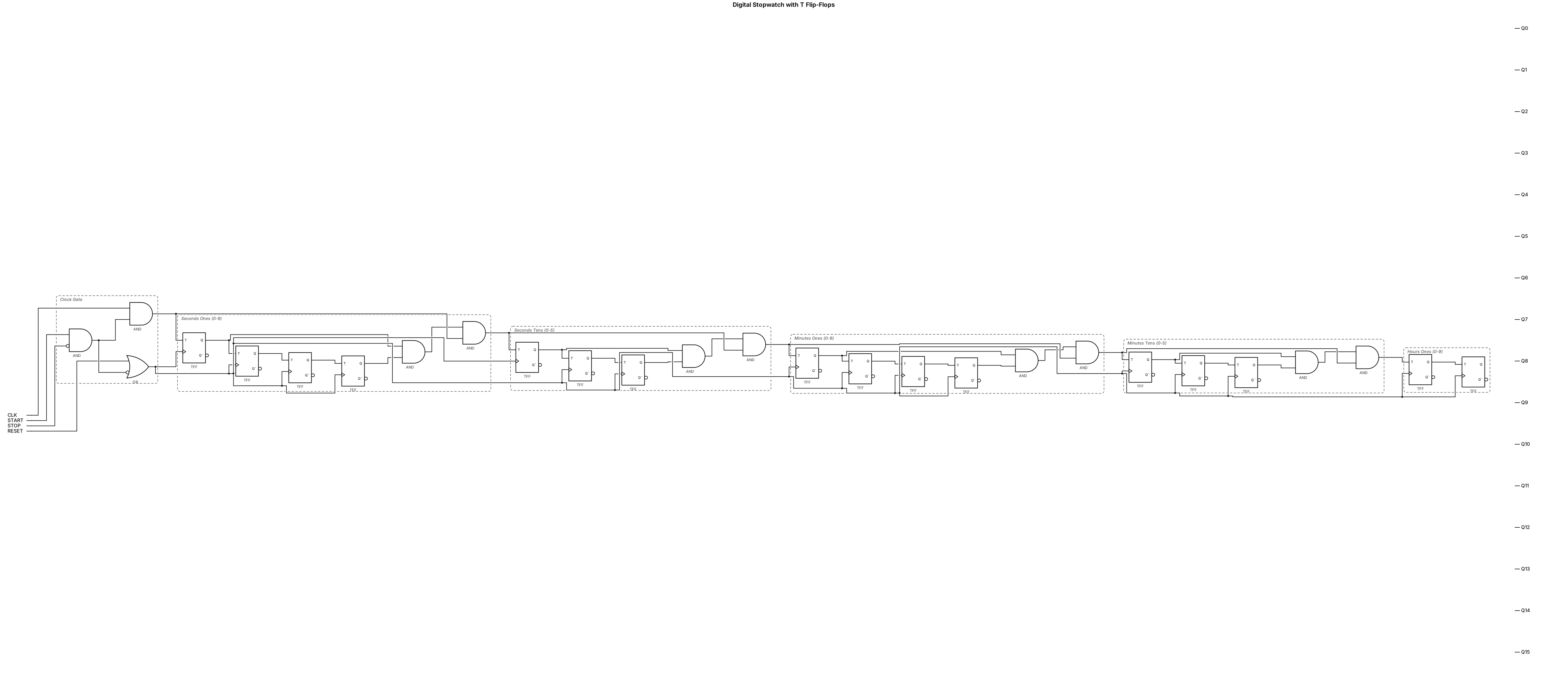
make me degital stopwatch using bild in ciruct make all get in one page use t flipflop
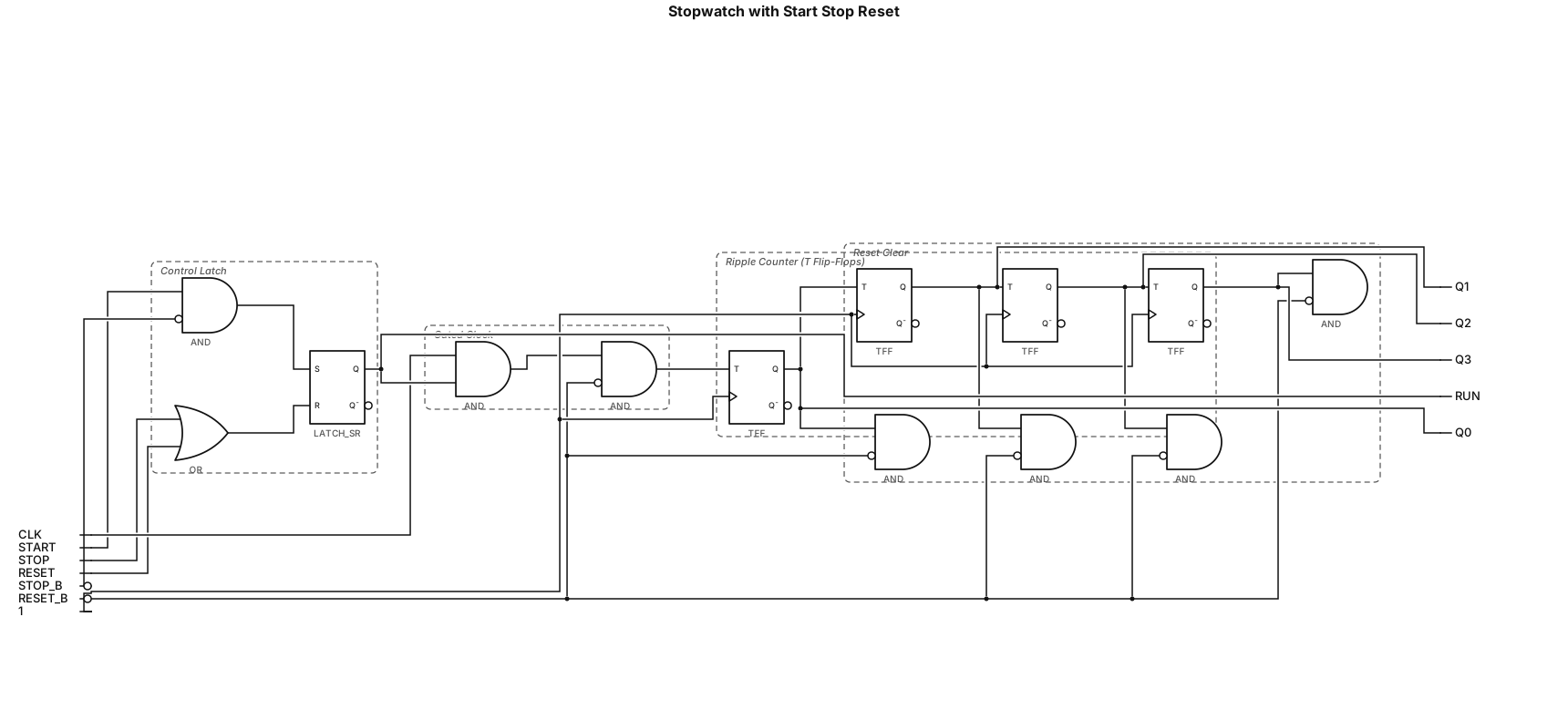
i want to make stop watch and it hsa stat butten , stop butten and rest butten and in this circut use clok puls and t flip flop and what you need and gove me diagram which i can impliment in logisim
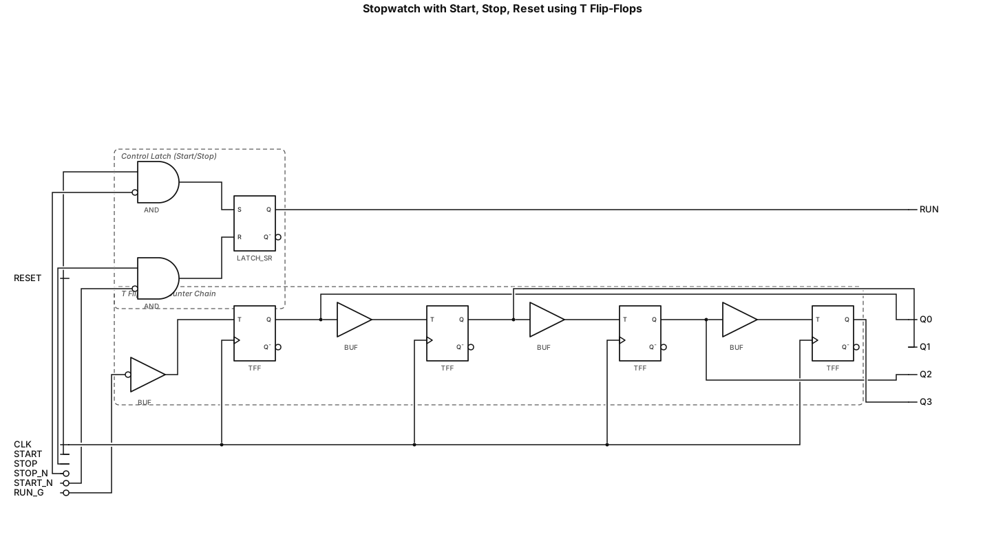
i want to make stop watch and it hsa stat butten , stop butten and rest butten and in this circut use clok puls and t flip flop and what you need
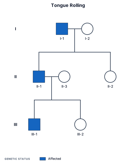
track 2-3 generation pedigree chart for tongue rolling. grandfather can roll tongue but grandmother cannot

Les plantes sont des êtres vivants appartenant au monde végétal qui se sont adaptés à la vie fixée sur un substrat. Quels sont alors les différentes innovations génétiques à l’origine de leur adaptation à la vie fixée, des schémas correctement légendés et des accès par sont attendus.

Design a 5V dual-vehicle counter circuit. The power supply uses an LM7805 voltage regulator. The input consists of two tactile push buttons: 'S1' (Low Sensor) and 'S2' (High Sensor), both tied to ground with 10k pull-down resistors. The combinational logic stage uses an SN74HC04N (Hex Inverter) and an SN74HC08N (Quad 2-Input AND gate). Route S2 into the SN74HC04N to invert it. Route S1 and the inverted S2 signal into an AND gate on the SN74HC08N; connect this output to the clock pin (Pin 1) of the first CD4026BE IC (Car Counter). Route S1 and the original non-inverted S2 signal into a second AND gate on the SN74HC08N; connect this output to the clock pin (Pin 1) of the second CD4026BE IC (Truck Counter). For both CD4026BE ICs: tie Pin 2 (Clock Inhibit) and Pin 8 (GND) to common ground. Tie Pin 16 (VCC) to 5V. Tie Pin 15 (Reset) to ground. Connect the outputs (a-g) of each CD4026BE to its own single-digit common-cathode 7-segment display, placing 330-ohm current-limiting resistors on all segment lines. Connect the common pins of both displays to ground. Ensure the VCC and GND pins of the SN74HC04N and SN74HC08N are correctly routed to the 5V and ground nets.
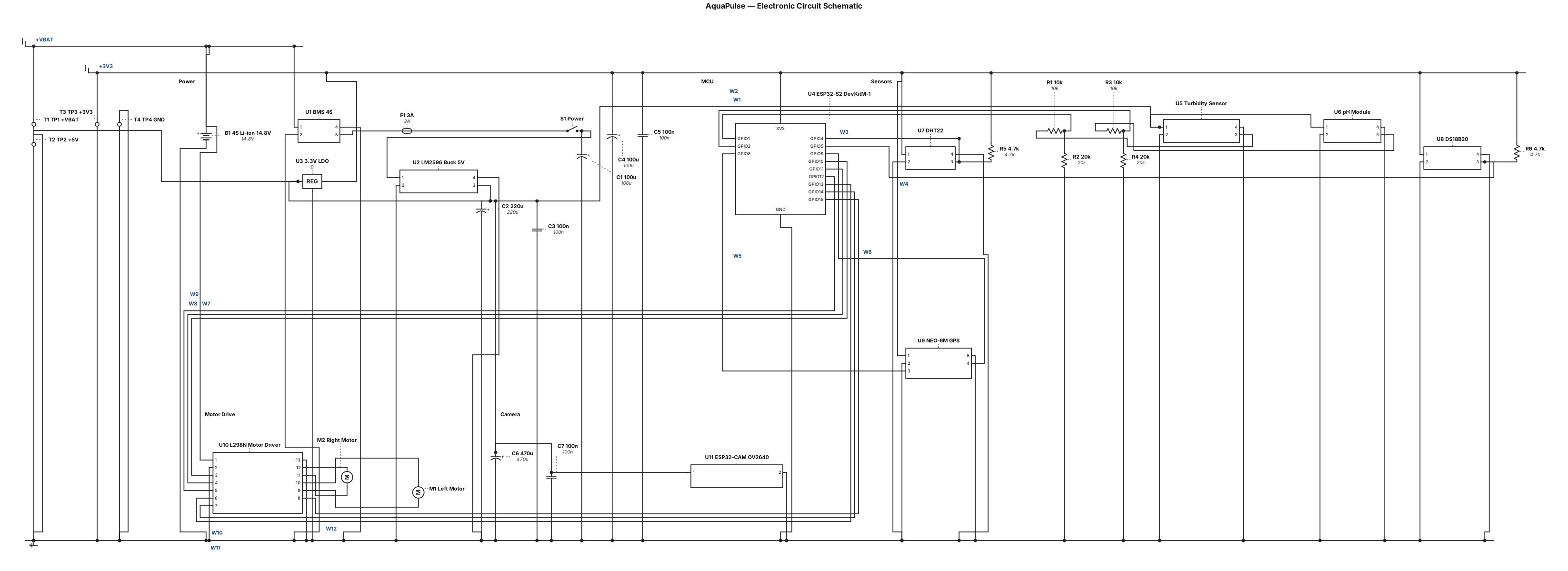
Draw a PURE ELECTRONIC CIRCUIT SCHEMATIC for my AquaPulse water-quality robot. Absolutely no block diagrams or flowcharts. Use standard circuit symbols and actual electrical wires: battery-cell symbols, zigzag resistors, fuse, switch, ground, voltage rails, connector pins and junction dots. Components: - 4S 14.8 V lithium-ion battery, BMS, 3 A fuse and switch. - LM2596 buck converter providing regulated 5 V. - ESP32-S2 DevKitM-1 with individually labelled GPIO pins. - Turbidity sensor AO to GPIO1 through a voltage divider. - pH module PO to GPIO2 through a voltage divider. - DHT22 DATA to GPIO4. - DS18B20 DQ to GPIO5 with 4.7 kΩ pull-up to 3.3 V. - NEO-6M GPS TX to GPIO8 and RX to GPIO9. - L298N motor driver: ENA GPIO10, IN1 GPIO11, IN2 GPIO12, IN3 GPIO13, IN4 GPIO14, ENB GPIO15. - Two DC motors connected to OUT1/OUT2 and OUT3/OUT4. - Separate ESP32-CAM with integrated OV2640 camera, powered from a suitable supply. Use named nets such as +VBAT, +5V, +3V3 and GND to avoid long crossing wires. Draw components using real electronic symbols, not rectangular functional blocks. Use a landscape A3 schematic with readable labels and a white background. Show Wi-Fi communication only as a separate dashed annotation, never as an electrical wire. Mark all unverified connections as provisional. Title: AquaPulse — Electronic Circuit Schematic.
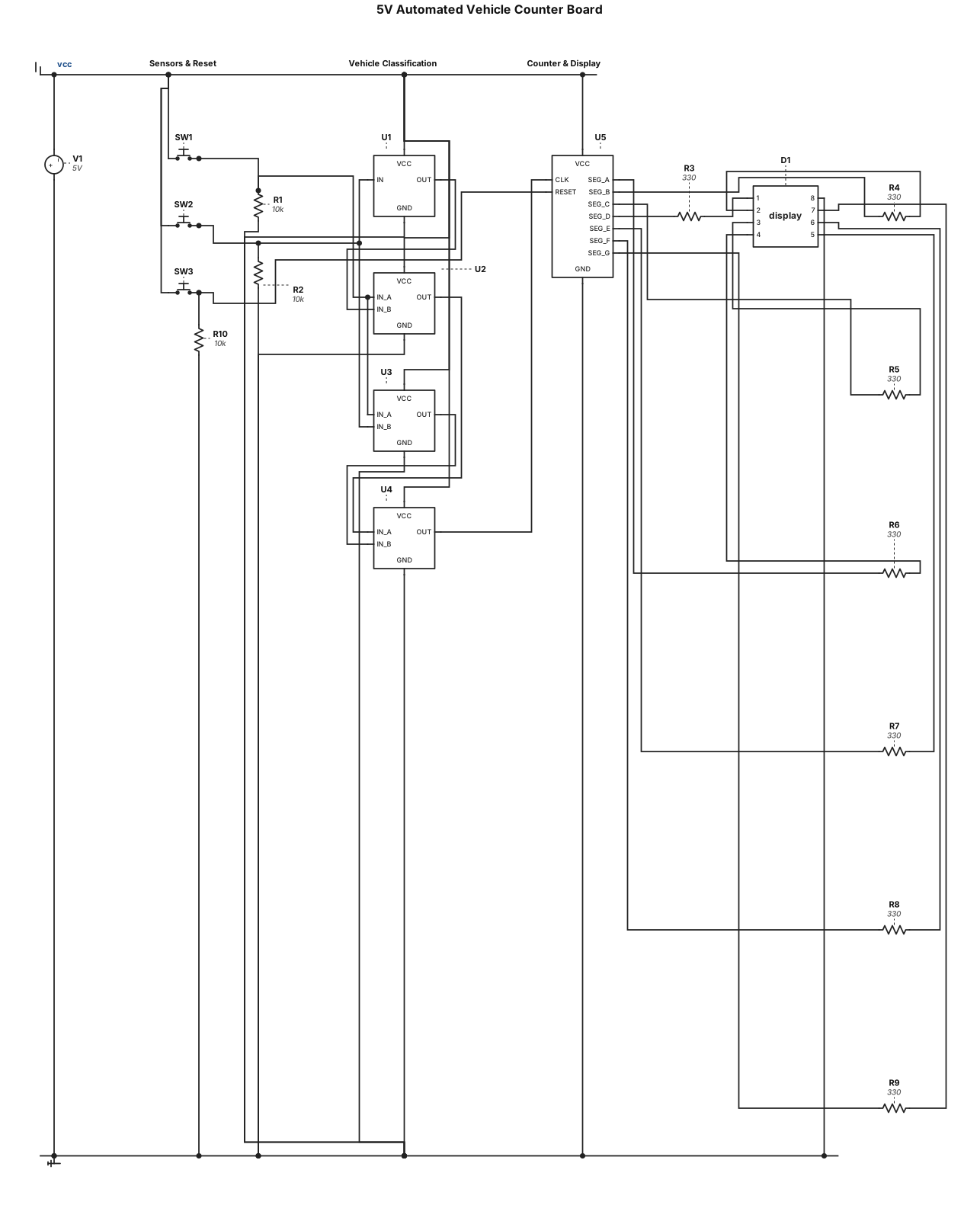
"Design a 5V automated vehicle counter board using exactly one CD4026BE decade counter/decoder IC driving a single-digit common-cathode 7-segment display (with 330-ohm series resistors). The input stage uses two sensors (simulated by push buttons): 'Sensor 1' (Low height) and 'Sensor 2' (High height). Route these signals through a combinational logic circuit using discrete CMOS gates: route Sensor 2 through a NOT gate (CD4069), then AND that output with Sensor 1 using an AND gate (CD4081) to classify a Car. Feed Sensor 1 and Sensor 2 into another AND gate to classify a Truck. Finally, route the outputs of both AND gates into a 2-input OR gate (CD4071). Connect the output of this OR gate to the clock input (Pin 1) of the CD4026BE. Add a master 'Reset' push button with a 10k pull-down resistor connected to the CD4026BE reset pin (Pin 15). Power the board via a USB-C connector.
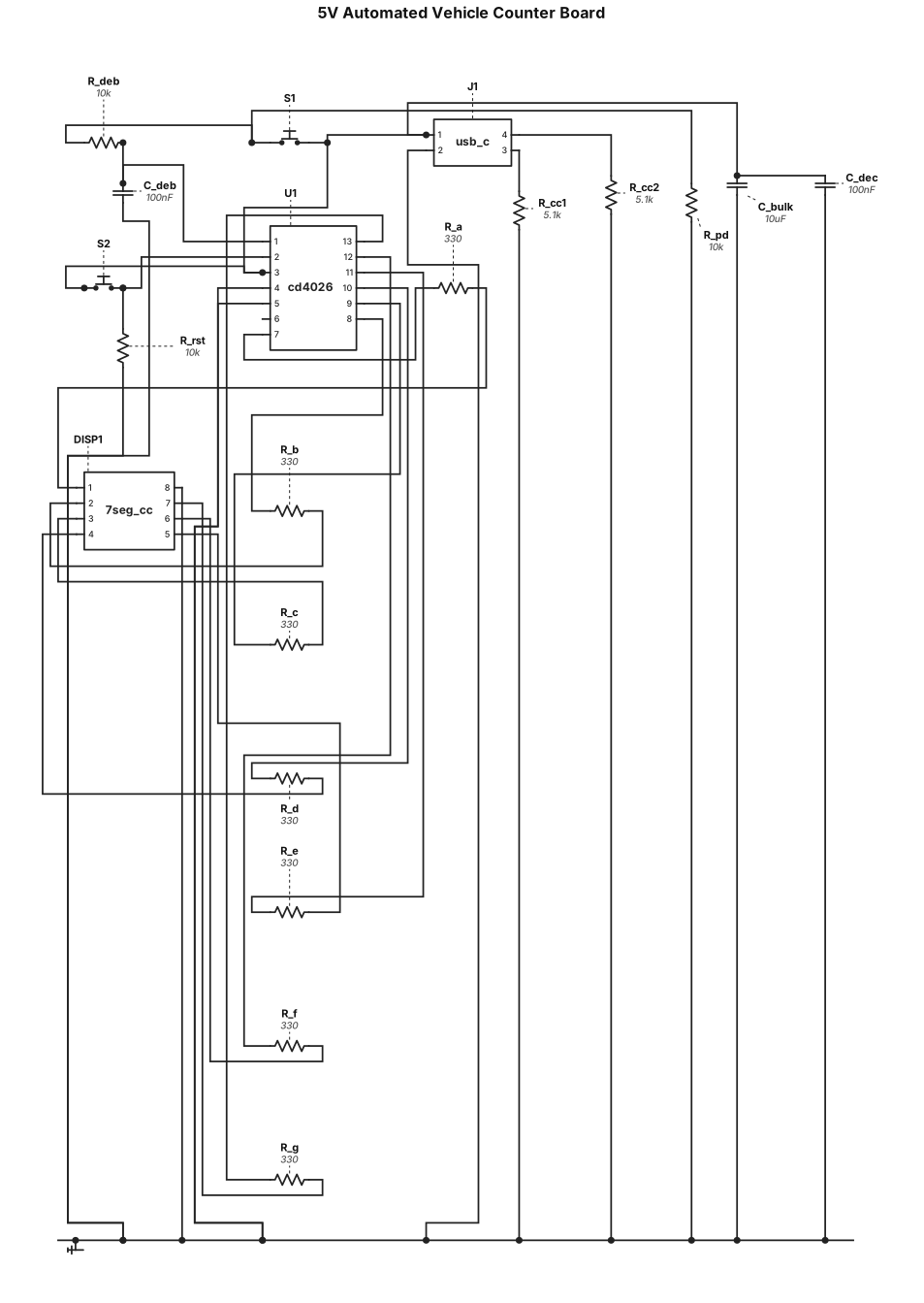
"Design a 5V automated vehicle counter board. The main component is a CD4026BE decade counter/decoder IC driving a single-digit common-cathode 7-segment display. Include 330-ohm current-limiting resistors between the IC and the display segments. Add two tactile push buttons: one for 'Vehicle Entry' connected to the clock input of the CD4026BE, and one for 'Reset' connected to the IC's reset pin. Include a hardware RC debounce circuit on the 'Entry' button to prevent multiple counts from switch bounce. Power the entire board via a simple USB-C connector.

Draw a SMALL, COMPACT, PORTRAIT block diagram. Maximum 6 boxes. Arrange every box in ONE vertical column, directly below the previous box. Do not use a landscape layout. ESP32-CAM ↓ Wi-Fi: images Laptop (YOLO) ↓ Bluetooth: commands ESP32 DevKit ↓ Motor Driver ↓ 4WD Motors Add “GPS → Pothole Map” as a tiny box beside the Laptop. White background, thin black arrows, simple blue rectangular boxes, short text. No icons, illustrations, extra text, large margins or decorative elements. The final diagram must be tall and narrow, not wide.
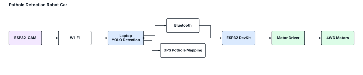
Create a compact vertical block diagram for a pothole detection robot car. Use a portrait layout (4:5 ratio), with small rectangular blocks stacked vertically and minimal spacing. ESP32-CAM → Wi-Fi → Laptop (YOLO pothole detection) → Bluetooth → ESP32 DevKit → Motor Driver → 4WD Motors. Add a small side branch from the laptop to GPS-based pothole mapping. Use short labels, thin arrows, a white background and professional blue-and-grey styling. Fit everything into one compact diagram. No illustrations, explanations, decorative elements or wide horizontal layouts.

Create a simple, professional block diagram showing only the command and data flow for a pothole detection robot car. Blocks and connections: 1. ESP32-CAM → Wi-Fi → Laptop (road images) 2. Laptop running YOLO → Bluetooth → ESP32 DevKit (movement commands) 3. ESP32 DevKit → Motor Driver → 4WD Motors (movement control) 4. Laptop → GPS Coordinates → Pothole Map (location mapping) Use rectangular blocks, clear directional arrows, short labels, a white background and a clean engineering-report style. Landscape layout. No extra details or illustrations.