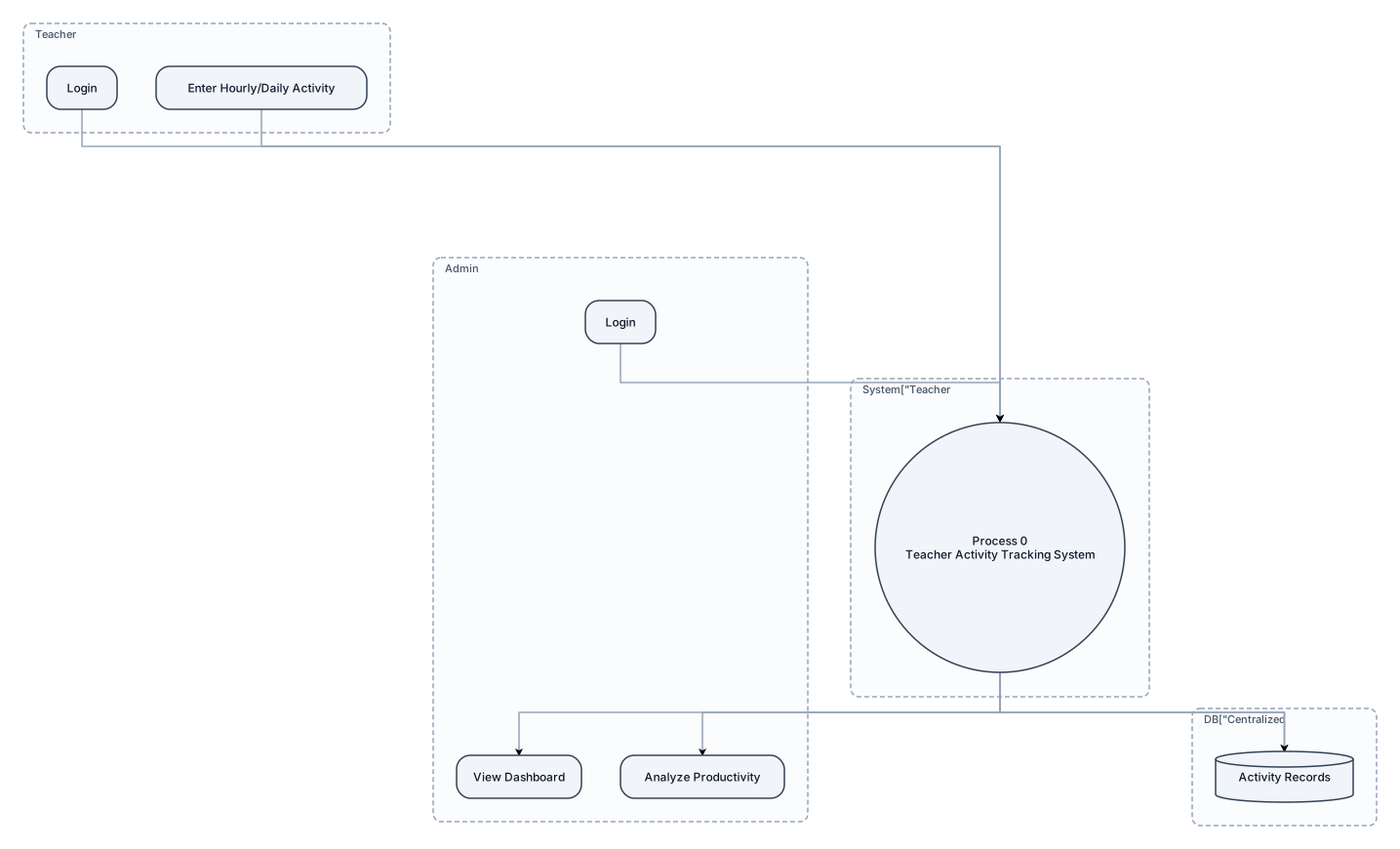
Create a simple, neat, college-project-style diagram for my MCA project, Teacher Activity Tracking System. Project details: - Frontend: HTML and CSS - Backend: Python Flask - Database: Centralized database - Teacher can log in and enter hourly or daily activity details. - Activity records are saved in the database. - Admin can access the dashboard, view teacher activity records, and analyze productivity. Generate the following diagrams one by one: 1. DFD Level 0 2. DFD Level 1 3. Use Case Diagram 4. ER Diagram 5. UML Class Diagram 6. System Flowchart 7. Sequence Diagram 8. Activity Diagram Design requirements: - Use simple black-and-white or light-colour diagrams. - Use standard symbols, correct arrows, clear labels, and proper relationships. - Keep the layout clean, readable, and suitable for a college project report. - Avoid unnecessary technical complexity, decorative graphics, and excessive colours. - Do not invent features or database tables that are not specified. Mark assumptions clearly. - Make the diagram editable and exportable as a high-quality PNG or PDF. - Generate only one diagram at a time, starting with DFD Level 0.
Diagram Examples from Real Visitor Prompts
Browse eligible diagrams shared by FreeDiagram visitors, inspect the exact prompts, and build your own version.
Browse 3282 real creationsAll visitor creations
Showing 961–984 of 3282. No stock examples or system defaults. Choose a tool, study a real result, then reopen its prompt as your starting point.
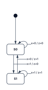
simple mealy circuit
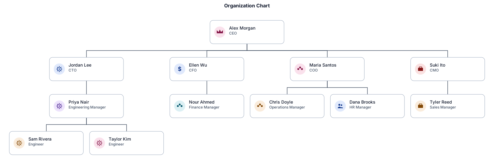
BASIC ORGANIZATIONAL CHART
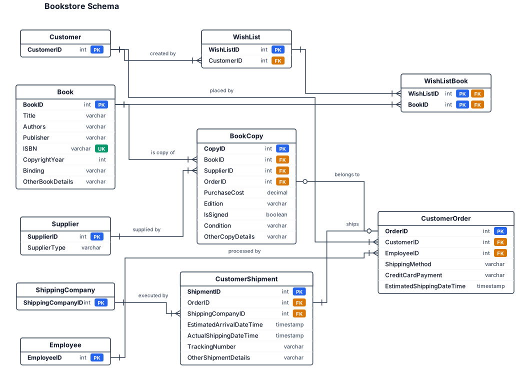
book - book copy=one book can have 0 to N book copies; each copy relates to 1 book supplier - book copy=one supplier can supply 0 to N book copies;each book copy comes from 1 supplier customer - wish list=one customer can create 0 to N wish lists;each wish list belongs to 1 customer wish list - book=a wish list can contain 0 to N books; a book can be on 0 to N wish lists customer - order=one customer can place 0 to N orders;each order belongs to 1 customer order - book copy=each order contains 1 to N book copies;each book copy can belong to 1 order employee - order=one employee can process 0 to N orders;each order is processed by 1 employee order - shipment= one order makes 0 or 1 shipment;each shipment belongs to 1 order shipment - shipping company=one shipping company can do 0 to N shipments;each shipment is executed by 1 shipping company Book=BookID (PK)*, Title, Authors (multivalued), Publisher, ISBN, CopyrightYear, Binding, OtherBookDetails Book Copy=CopyID (PK)*, PurchaseCost, Edition, IsSigned, Condition, OtherCopyDetails Supplier=SupplierID (PK)*, SupplierType (bookstore or individual)* Customer=CustomerID (PK)* Wish List=WishListID (PK)* Customer Order=OrderID (PK)*, ShippingMethod, CreditCardPayment, EstimatedShippingDateTime Employee=EmployeeID (PK)* Customer Shipment=ShipmentID (PK)*, EstimatedArrivalDateTime, ActualShippingDateTime, TrackingNumber, OtherShipmentDetails Shipping Company=ShippingCompanyID (PK)*
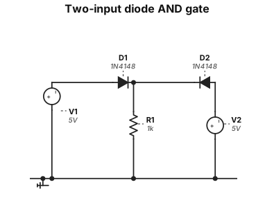
"Two-input diode AND gate: two diodes D1 and D2 with anodes connected to input A and input B respectively, cathodes tied together at the output node. A 1kΩ resistor pulls the output node to GND. Label inputs A and B, output Y, and the diodes D1, D2. Use standard 1N4148 diode symbols."
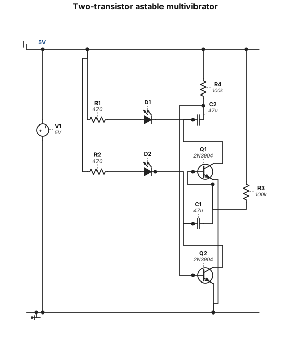
"Two-transistor astable multivibrator: two NPN transistors Q1 and Q2. Each collector has an LED in series with a 470Ω resistor to +5V. Each base is connected to +5V through a 100kΩ resistor. A 47µF capacitor cross-couples Q2's 2n3904 collector to Q1's 2n3904 base, and another 47µF capacitor cross-couples Q1's collector to Q2's base. Both emitters go to GND."
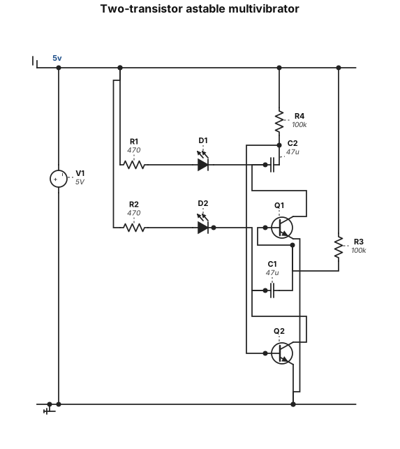
"Two-transistor astable multivibrator: two NPN transistors Q1 and Q2. Each collector has an LED in series with a 470Ω resistor to +5V. Each base is connected to +5V through a 100kΩ resistor. A 47µF capacitor cross-couples Q2's collector to Q1's base, and another 47µF capacitor cross-couples Q1's collector to Q2's base. Both emitters go to GND."
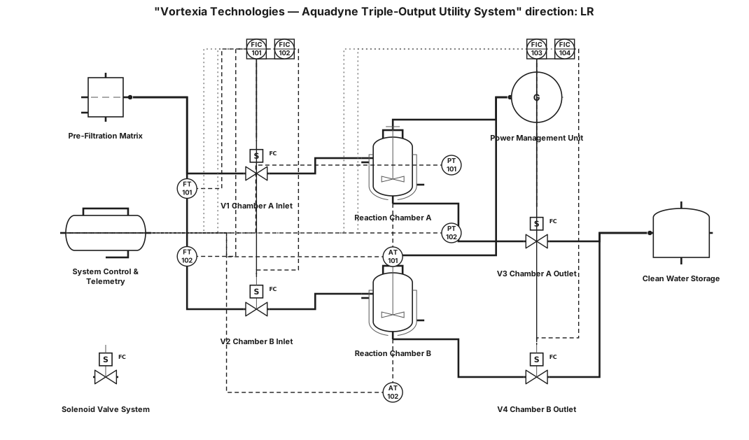
A professional, complex technical patent blueprint and schematic illustration for a "Vortexia Technologies - Aquadyne Triple-Output Utility System." The style must be white technical drawing lines on a dark blue engineering blueprint background, complete with a grid overlay and visible fold lines. The schematic must be organized into distinct, connected sections: Main Section (Center): A detailed cross-section view of the dual cylindrical reaction chambers. Clearly label the interior "Zinc Anodes (Negative)" and "Copper Cathodes (Positive)" plates immersed in fluid. Show arrows for "Wastewater Inlet" and precise labels for three distinct output lines: "Output 1: Clean Water," "Output 2: Graded Electricity," and "Output 3: Pure Oxygen." Sub-system 1 (Top Right): An exploded view of the "Pre-Filtration Matrix," showing stages like a coarse sediment screen and grease trap. Sub-system 2 (Middle Right): The "Power Management Unit (PMU)," illustrating the "12V Mini Solar Panel" and the "XL6009 Boost Converter" circuit. Sub-system 3 (Bottom Left): A schematic for "System Control & Telemetry," showing the "ESP32 Microcontroller Board" connected to the "TDS Sensor," "Voltage Sensor," "OLED Display," and "Remote Telemetry (Wi-Fi)." Sub-system 4 (Bottom Center): An automated diagram of the "Solenoid Valve System (V1, V2, V3, V4)" for 24/7 dual-chamber routing. Include a formal title block in the top-left corner with the company logo, project name, and a scale reference. Include a detailed bill of materials table in the bottom-right corner listing key components (e.g., ESP32, TDS Sensor, Solar Panel, Filter Cartridge). The entire diagram must be densely interconnected with labeled pipes, wires, and flow arrows. Extremely high detail, 8k resolution, photorealistic blueprint texture.
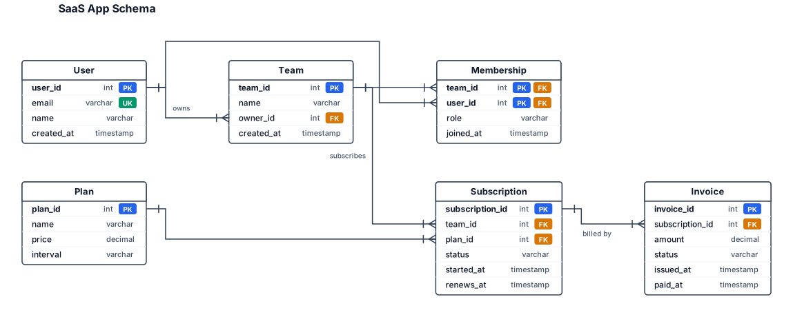
An entity-relationship diagram for a SaaS app with users, teams, subscriptions, and invoices
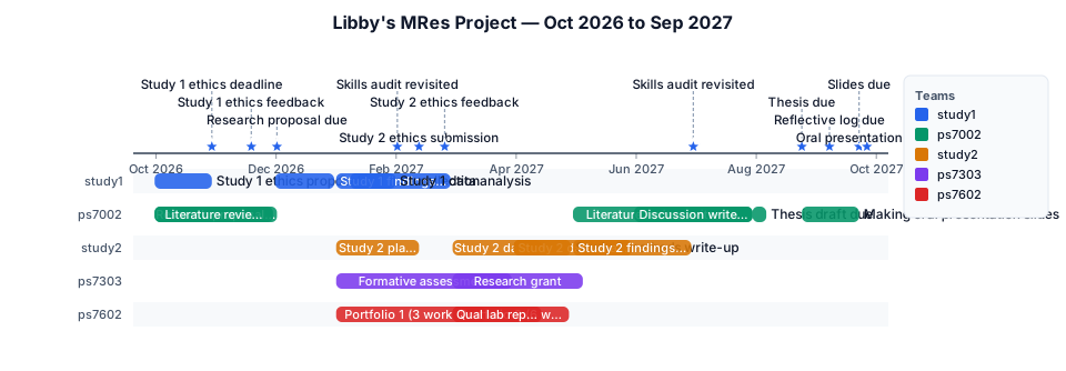
A timeline of Libby's MRes project, spanning October 2026 to September 2027 with the following deadlines, grouped by their overarching project: Study 1: Study 1 ethics deadline = 30th October Study 1 ethics feedback = 19th November Working on Study 1 ethics proposal = Early October until 30th October Study 1 start data collection = Start of December until end of December Study 1 data analysis = Second week of January until End of January Writing up findings and methods from Study 1 = January to February Study 2: Study 2 planning and writing ethical approval= Start of January until 12th February Study 2 ethics submission = 12th February 2027 Study 2 ethics feedback = 25th February 2027 Study 2 data collection = Through March to mid April Study 2 data analysis = Through April and May Writing up Study 2 findings = May-June Writing up Study 2 methods = April PS7002 Assessments: Research Proposal due date = 2 December 2026 Working on research proposal = Early October to 2nd December Thesis due date = 25 August Thesis draft due = End of July/ Start of August Literature review write up = October to November with a break and then resuming May to July Discussion write up = June to End of July Reflective Log = 8 September Oral presentation = Slides due 23 September, presenting w/c 27 September Making slides for oral presentation = Start end of August ends on 23rd September Skills audit revisited = 1st February 2027 AND 1st July 2027 PS7303 Assessments: Research grant = March to 6 May Formative assessment = Start of January to end of March PS7602 Assessments: Portfolio 1 (3 worksheets) = Start of January to 18 March Portfolio 2 (6 worksheets) = March until 29 April Qual lab report = March until 15 April (the deadlines run from October 2026-September 2027, so months such as January or March will be 2027 not 2026)
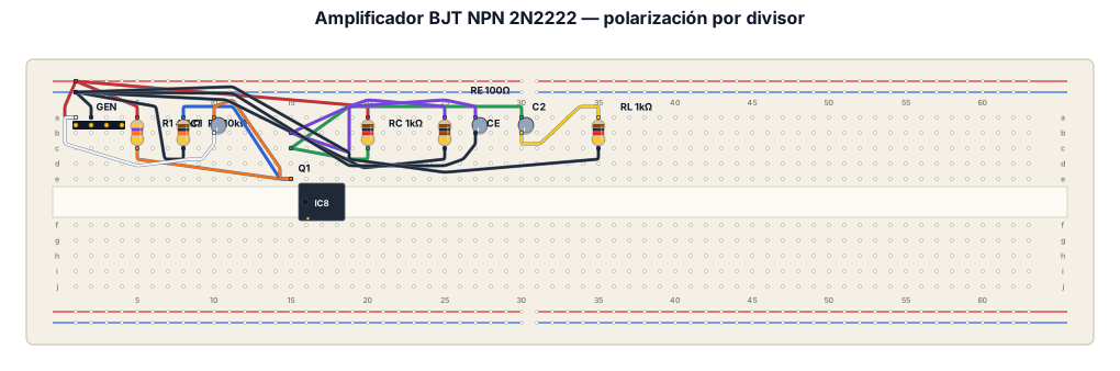
Crea un diagrama de cableado en protoboard para un amplificador con un transistor BJT NPN 2N2222. Conecta una fuente de alimentación DC de 9V a los rieles positivo y negativo de la protoboard. Conexiones de la Base: Conecta una resistencia R1 (47 kOhm) desde el riel positivo a la Base. Conecta una resistencia R2 (10 kOhm) desde la Base al riel negativo (GND). Conecta el polo positivo de un capacitor C1 (10 uF) a la Base, y su polo negativo al terminal positivo de un generador de señal de CA (1 KHz). El negativo del generador va a GND. Conexiones del Colector: Conecta una resistencia RC (1 kOhm) desde el riel positivo al Colector. Conecta el polo positivo de un capacitor C2 (10 uF) al Colector. Conexiones del Emisor: Conecta una resistencia RE (100 Ohm) desde el Emisor a GND. Conecta el polo positivo de un capacitor CE (10 uF) al Emisor y su polo negativo a GND (en paralelo con RE). Conexiones de Salida: Conecta una resistencia de carga RL (1 kOhm) desde el polo negativo de C2 hacia GND.
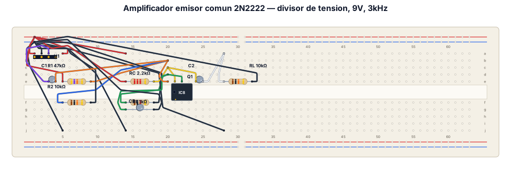
Un diagrama en protoboard de un amplificador usando un transistor bipolar BJT NPN 2N2222 con polarizacion divisor de tension en configuracion emisor comun con R1, R2, RC y la resistencia de carga RL. Ademas C1, C2 y CE (capacitor de desacople), fijar el voltaje en continua en 9V y la corriente alterna con un bajo voltaje y frecuencia fija en 3KHz
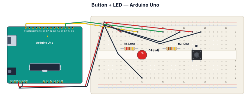
A breadboard wiring diagram for an Arduino Uno reading a button press and lighting an LED: button with pull-down resistor on D2, LED with 220-ohm resistor on D13
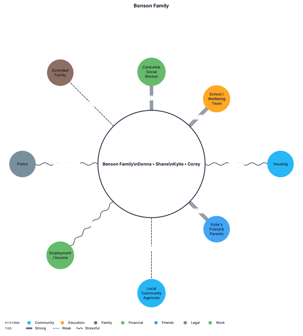
Can you generate an ecomap based on this Use solid line for active, supportive connection Dashed line for stressed connection Dotted line for formal, limited connection Main: BENSON FAMILY Donna • Shane Kylie • Corey Centrelink social worker School / wellbeing team Housing Kylie's friend & friend's parents Local community agencies (suggested) Employment / income Police (warning to Kylie) Extended family (tenuous links) Key: solid = active/supportive connection; dashed = strained or stress-related connection; dotted = limited, formal, or potential connection. Ecomap reflects information in the case and should be checked collaboratively with family members.
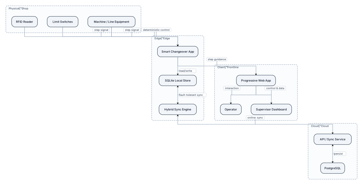
Paper and worker memory have traditionally been used for manual changeover in assembly lines, incurring significant amounts of time and money in the change itself, as well as a plethora of issues and divergences in the initial production batch. In industrial manufacturing, changeovers are the bottleneck of massive manufacturing process, as they rely heavily on tacit knowledge and maintain the usage of ad hoc production. In this publication, we introduce a context-aware smart changeover technology for the replacement of paper instructions and deterministically controlling at the hardware level. The switch platform was developed with a highly responsive Progressive Web App front end and ESP32 edge node back end that provides a Node.js JavaScript engine. Individual physical sensors (RFID reader and limit switches) were integrated and attached to the edge node in order to test proper steps of operations at a machine level. Fault tolerant hybrid synchronization mechanism over SQLite at the edge node and PostgreSQL at cloud back end was developed. The hybrid synchronization mechanism was implemented at the edge node and the cloud level, and allowed the operation without being affected by possible network disconnection on shop floor. Proofs-of-concepts (PoCs) with quantitative field tests and prototypes showed that changeover time could be shaved 35% and sequential errors abolished. Smart changeovers are executed on the shop-floor through low-cost IoT edge devices that share the shop floor passive knowledge with an interactive shop-floor instruction system. Also, the framework gives frontline supervisors greater shop floor control and data that they can act on, without violating the privacy and autonomy of the workforce.
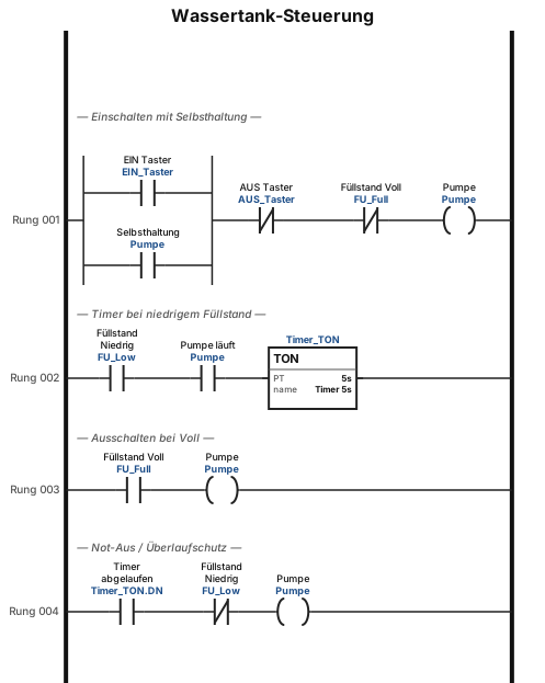
Erstelle einen Plan um einen Wassertank zu steuern. Mit an und aus Taster einem füllstandssensor und einem Timer
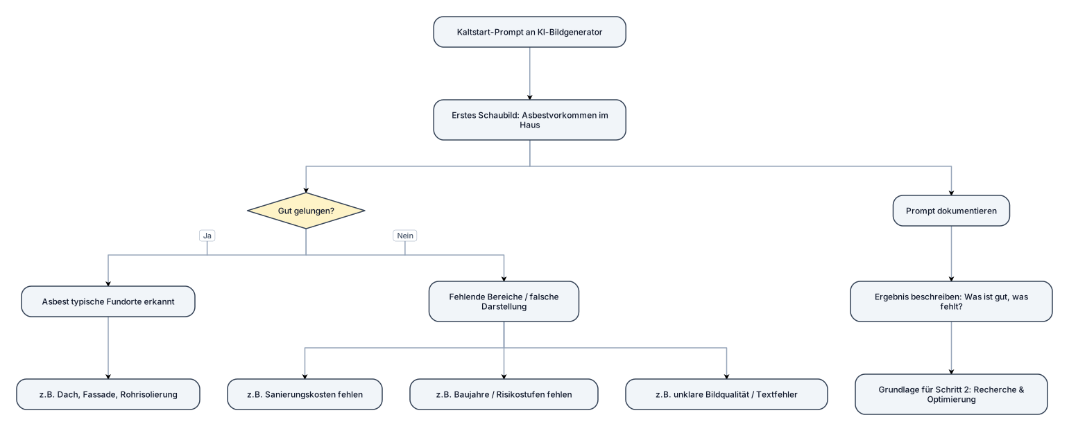
Ziel dieses Arbeitsblatts: Ihr untersucht das Vorkommen von Asbest in Gebäuden und die Kosten einer Sanierung. Dabei nutzt ihr eine künstliche Intelligenz (KI) zur Bildgenerierung (z.B. Midjourney, DALL-E oder Adobe Firefly), um ein informatives Schaubild zu erstellen. Ihr optimiert euer Ergebnis durch gezielte Recherche. Schritt 1: Der erste Versuch (Kaltstart-Prompt) Erstellt mit einer KI eurer Wahl ein erstes Schaubild zum Thema Asbestvorkommen im Haus. Nutzt dafür euer aktuelles Vorwissen, ohne vorher zu recherchieren. Aufgabe: Notiert hier euren genutzten Prompt und beschreibt kurz das Ergebnis (Was ist gut, was fehlt?):
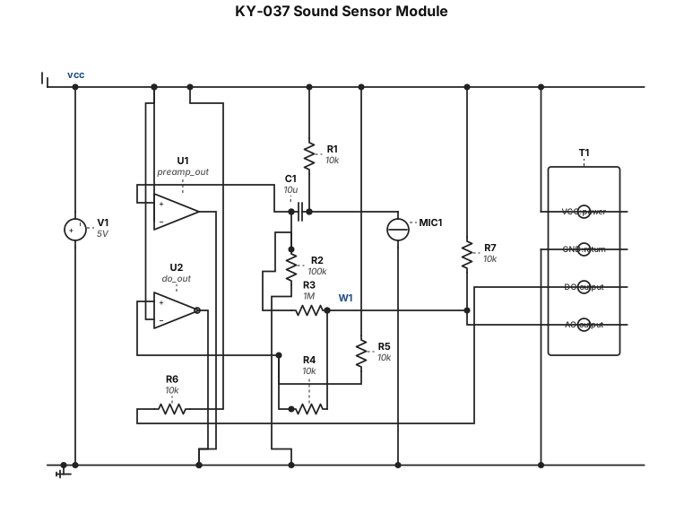
diagram dari KY-037
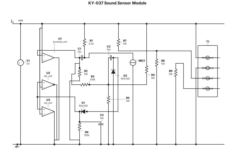
KY-037
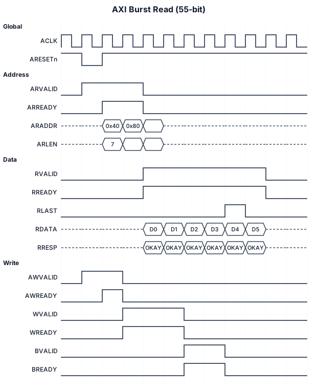
AXI burst 55 bit
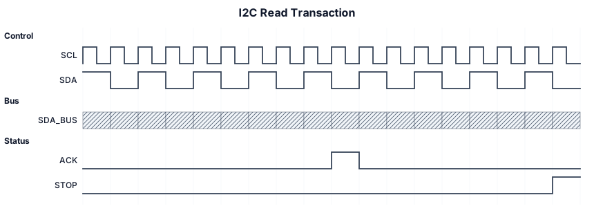
A timing diagram for an I2C read transaction: SCL clock, SDA with START condition, 7-bit address byte, ACK bit, data byte, and STOP condition
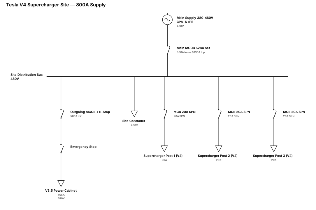
Create a Single-line diagram: Installation of 3 Tesla V4 Supercharger posts, 1 V3.5 Power Cabinet and 1 site controller, Main Supply 800A MCCB 630A, 4-pole MCCB, LSIG, 50kA, set at 528A. Outgoing 4-pole MCCB, minimum 500A, with emergency stop. 3 × 20A SPN MCBs. The system requires a 380–480V, 465A, three-phase + N + PE supply. Power cables must be suitable for the specified 480A requirement, with separate protective earthing conductors. Emergency & Shutdown: Emergency stop arrangements must be provided at the charging stalls.
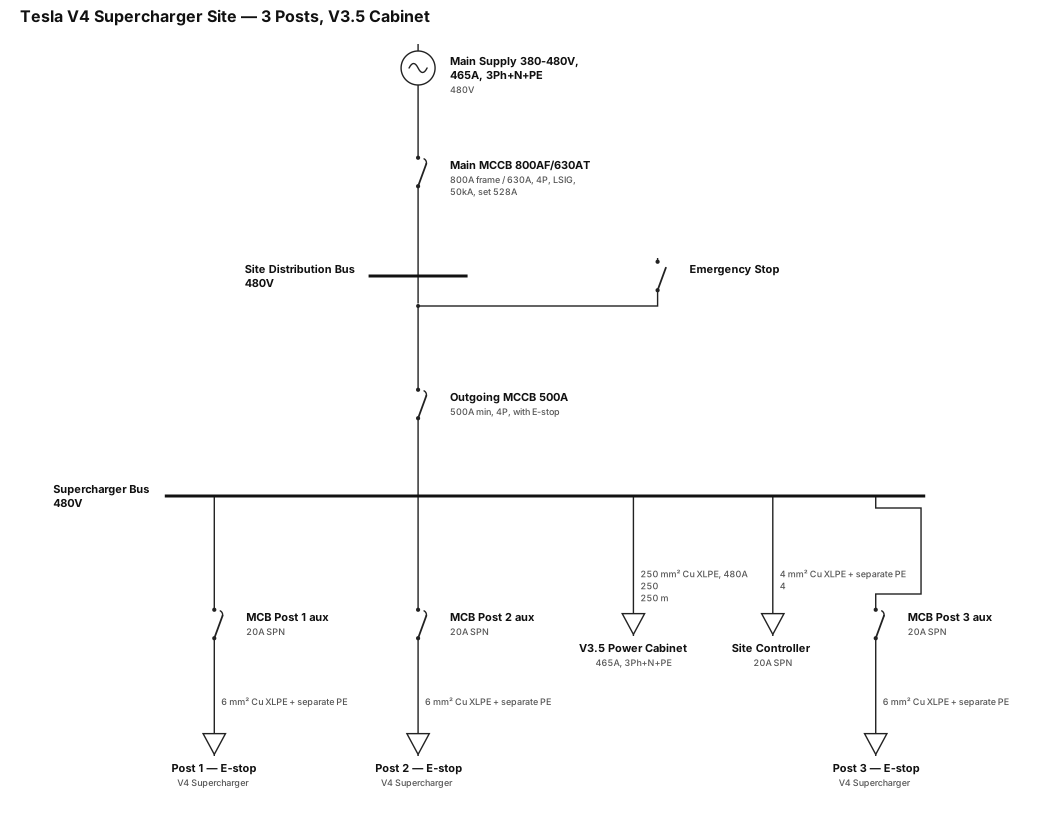
Create a Single-line diagram: Installation of 3 Tesla V4 Supercharger posts, 1 V3.5 Power Cabinet and 1 site controller, Main Supply 800A MCCB 630A, 4-pole MCCB, LSIG, 50kA, set at 528A. Outgoing 4-pole MCCB, minimum 500A, with emergency stop. 3 × 20A SPN MCBs. The system requires a 380–480V, 465A, three-phase + N + PE supply. Power cables must be suitable for the specified 480A requirement, with separate protective earthing conductors. Emergency & Shutdown: Emergency stop arrangements must be provided at the charging stalls. with cable size of 250 meter
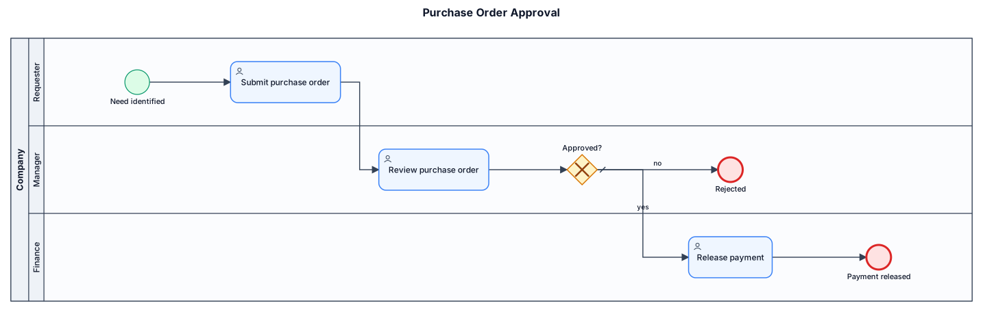
A BPMN diagram of a purchase-order approval process across three lanes: requester submits a PO, manager reviews and approves or rejects, finance releases payment