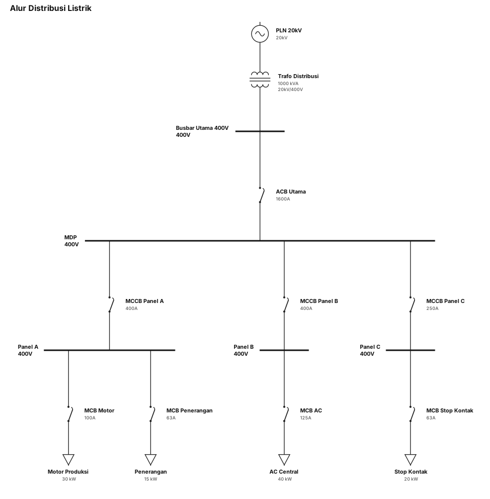
buatkan saya sebuah single line diagram alur distribusi listrik.
NODE ARCHIVE · REAL DIAGRAM BRIEFS
Diagram Examples from Real Visitor Prompts
Browse eligible diagrams shared by FreeDiagram visitors, inspect the exact prompts, and build your own version.
Browse 3298 real creationsCOMMUNITY OUTPUTS · EXACT PROMPTS
All visitor creations
Showing 1729–1752 of 3298. No stock examples or system defaults. Choose a tool, study a real result, then reopen its prompt as your starting point.
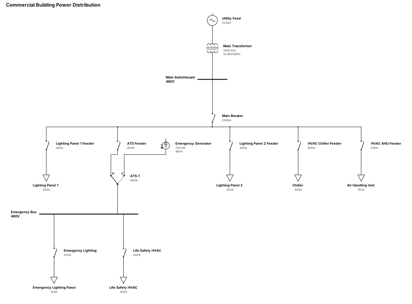
A single-line diagram for a commercial building: utility feed through a main transformer to a 480V switchboard, then to lighting panels, HVAC equipment, and an emergency generator with ATS

1. Sähköposti -> kyberhyökkäys -> tietomurto -> mahdollinen tiedustelu 2. Mahdollinen tiedustelu -> tietojen vuotaminen -> kyky käyttää tietoa väärin -> laajempi hyökkäys 3. Laajempi hyökkäys -> kriittisen infran haavoittuvuus -> sähköverkon haavoittuvuus -> yhteiskunnallinen resilienssi 4. Mahdollinen tiedustelu -> tietojen vuotaminen -> kyky käyttää tietoa -> päätöksenteon legimiteetti
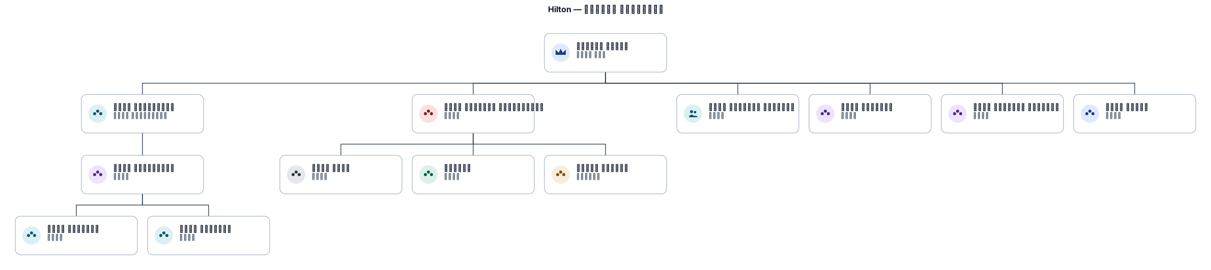
صمم لي هيكل تنظيمي هرميا مبسط لشركة hilton اجعل مدير العام في اعلى الهيكل وتحته مدير الاستقبل ومدير الاغذية والمشروبات ومدير الموارد البشرية مدير المالية ومدير تدبير الفندقي ومدير الامن وتحته مدير الاستقبال ضع مشرف ااستقبال وموظفيم استقبال تحت مدير الاغذية والمشروبات ضع مشرف مطعم الطهاة وموظفين الخدمة تحت مدير التدبير للفنادق
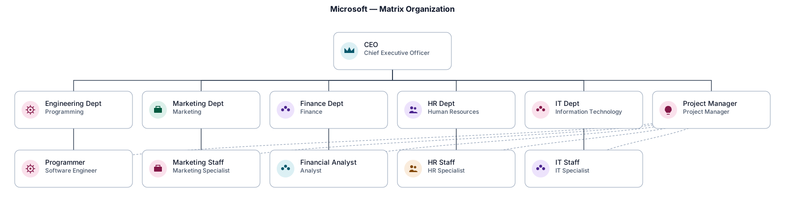
صمم لي هيكلا تنظيميا مصفوفا مبسطا لشركة مايكروسوفت استخدم الاقسام الاتية :قسم البرمجة,قسم التسويق,قسم المالية,قسم الموارد البشرية,قسم تكنلوجيا المعلومات ,اضف مدير مشروع جديد في المنتصف واجعل فريق المشروع يتكون من مبرمج وموظف تسويق ومحلل مالي وموظف موارد بشرية وموظف تكنلوجيا المعلومات ,اظهر في المخطط ان كل موظف مرتبط بقسمه الاصلي وفي الوقت نفسه يعمل تحت اشراف مدير المشروع ,اجعل خطوط الارتباط واضحة لتوضيح طبيعة الهيكل المصفوفي

صمم لي هيكلا تنظيميا هرميا مبسطا لشركة ماكدونلدز اجعل المدير العام في اعلى الهيكل و تحته مدير العمليات و مدير التسويق و مدير موارد البشرية و مدير الماليه و مدير المبيعات تحت مدير العمليات ضع مشرف الفرع و مشرف المطبخ و موظفي تجهيز الطلبات و تحت مدير التسويق ضع موظف تسويق الرقمي و موظف الاعلانات و تحت مدير موارد البشرية ضع موظف التوظيف و موظف تدريب تحت مدير الماليه محاسب و موظف الرواتب و تحت مدير المبيعات ضع مشرف المبيعات و موظفي خدمة الزباين رتب الجميع داخل مخطط تنظيمي واضح من الاعلى الى الاسفل

صمم لي هيكلا تنظيميا مسطحا مبسط لشركة زارا اجعل المدير التنفيذي في اعلى الهيكل وتحته مباشرة : مدير التسويق , مدير المبيعات , و مدير الموارد البشرية , مدير المخزون , مدير خدمة العملاء ,مدير المتجر . تحت مدير المتجر وضع : مشرفي الاقسام وموظفي المبيعات . تحت مدير المخزون ضع : موظفي المستودع . تحت مدير خدمة العملاء ضع : موظفي خدمة العملاء . اجعل عدد المستويات الادارية قليلا , و رتب الهيكل بشكل واضح يبين قرب الموظفين من الادارة العليا

صمم الي هيكلا هولاقراطيا مبسطا لشركة zapposقسم الشركة الى فريق مستقلة بدل التسلسلالاداري التقليدي استخدم الفرق الاتية فريق خدمة العملا فريق التسويق فريق التقنية فريق العمليات فريق تجربة الموظفين. داخل كل فريق ضع اعضاء مثل :منسق الفريق،موظف او موظفين متخصصين،ممثل اتصال مع الفرقالاخرى. لا تجعل هناك مديرا واحد يتحكم بجميع القرارات، با اظهر ان المسؤؤليات والصلاحيات موزعة بين الفريق وانها تتعاون مع بعضها البعض بشكل مباشر.
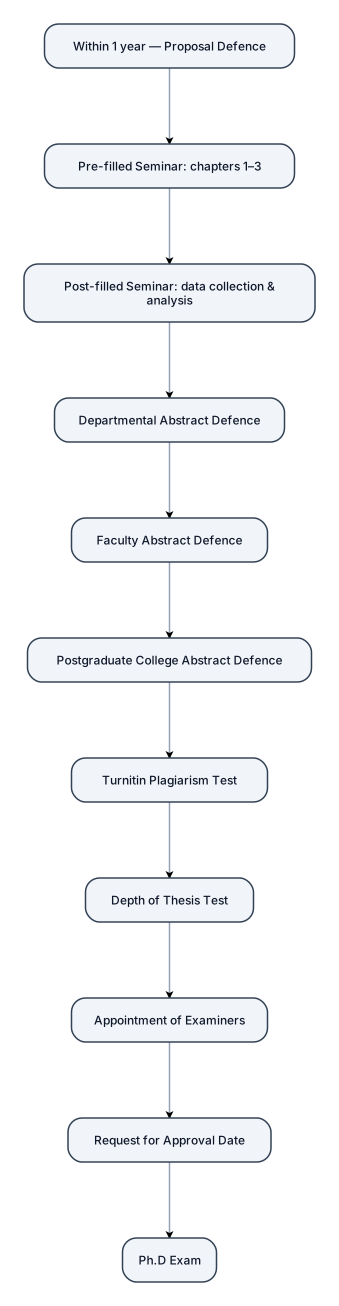
Ph.D Program chart 1. Within 1 year — Proposal Defence 2. Pre-filled Seminar (chapter 1—3 of project…) 3. Post-filled Seminar (after collecting data and analysis...) 4. Departmental Abstract Defence 5. Faculty Abstract Defence 6. Postgraduate College Abstract Defence 7. Turnitin Plagiarism Test 8. Depth of Thesis Test 9. Appointment of Examiners 10. Request for Approval Date 11. Ph.D Exam. Make the above into a Colourless schematic diagram
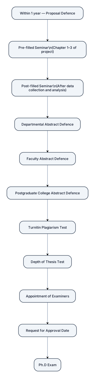
Ph.D Program chart 1. Within 1 year — Proposal Defence 2. Pre-filled Seminar → (chapter 1—3 of project…) 3. Post-filled Seminar → (after collecting data and analysis...) 4. Departmental Abstract Defence 5. Faculty Abstract Defence 6. Postgraduate College Abstract Defence 7. Turnitin Plagiarism Test 8. Depth of Thesis Test 9. Appointment of Examiners 10. Request for Approval Date 11. Ph.D Exam. Make the above into a Colourless schematic diagram

An org chart for a 30-person startup with a PM, SM, DSM, and Section leader of Project at the top — then engineering, supervisor, BIM/CAD, and HSE teams below with their leads
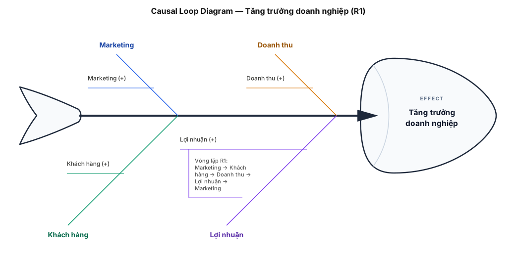
Tạo Causal Loop Diagram về tăng trưởng doanh nghiệp: Marketing → Khách hàng → Doanh thu → Lợi nhuận → Marketing. Tất cả quan hệ (+), tạo vòng lặp R1.
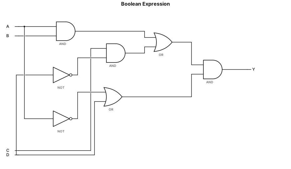
((A * B) + (C * NOT D)) * (NOT A + D)
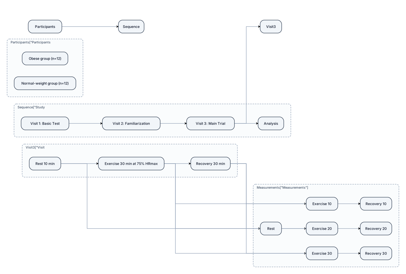
Create a horizontal scientific study design figure. Participants (n=24) are divided into: Obese group (n=12) and Normal-weight group (n=12). Study sequence: Visit 1: Basic Test → Visit 2: Familiarization → Visit 3: Main Trial → Analysis Visit 3 consists of: Rest 10 min → Exercise 30 min at 75% HRmax → Recovery 30 min Measurements are taken at: Rest, Exercise 10, Exercise 20, Exercise 30, Recovery 10, Recovery 20, Recovery 30. Use a clean academic journal style with a horizontal layout.
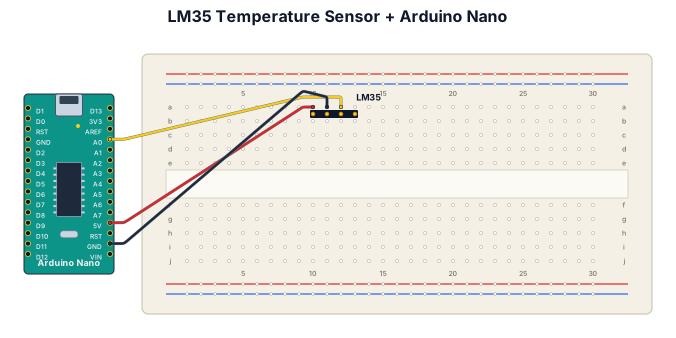
A breadboard wiring diagram for an Arduino nano detecting the room temperature with an LM35: connect +5 pin of LM35 to a 5V terminal of Arduino, connect right pin of LM35 to A0 terminal of Arduino, connect middle pin from LM35 to Arduino GND, also place LM35 onto breadboard. The LM35 has three pins
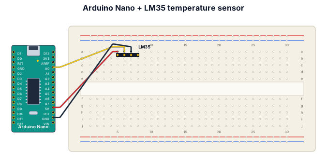
A breadboard wiring diagram for an Arduino nano detecting the room temperature with an LM35: connect +5 pin of LM35 to a 5V terminal of Arduino, connect Vout pin of LM35 to A0 terminal of Arduino, connect GND pin from LM35 to Arduino, also place LM35 onto breadboard. The LM35 has three pins
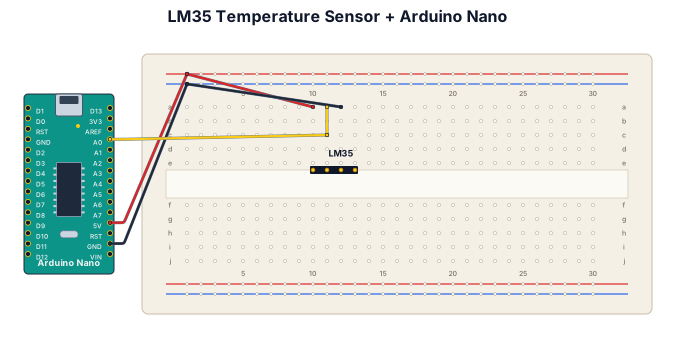
A breadboard wiring diagram for an Arduino nano detecting the room temperature with an LM35: connect +5 pin of LM35 to a 5V terminal of Arduino, connect Vout pin of LM35 to A0 terminal of Arduino, connect GND pin from LM35 to Arduino, also place LM35 onto breadboard
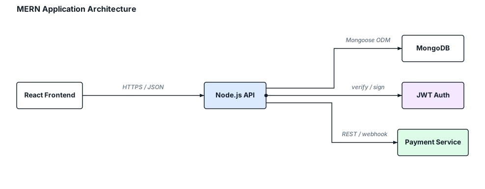
Create an architecture diagram for a MERN application with React frontend, Node.js API, MongoDB database, JWT authentication and an external payment service
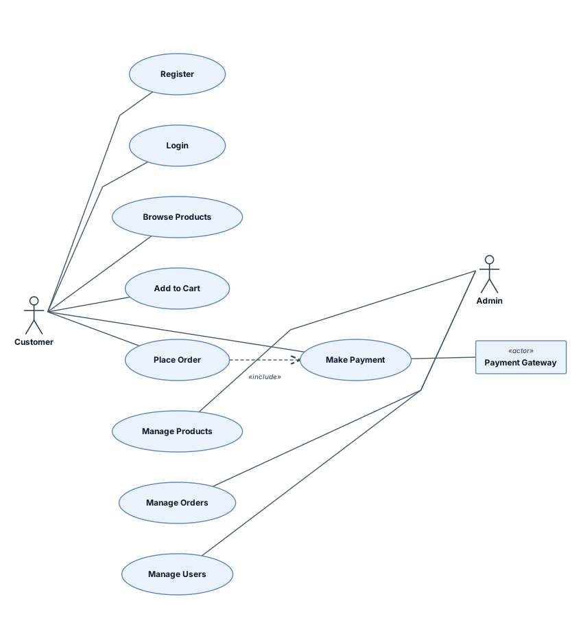
Create a UML use case diagram for an e-commerce system. Actors are Customer, Admin and Payment Gateway. Customer can register, login, browse products, add products to cart, place orders and make payments. Admin can manage products, orders and users
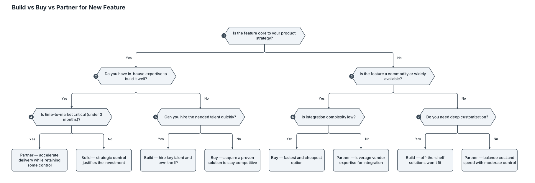
A decision tree for whether a startup should build, buy, or partner for a new feature, evaluating cost, speed, and strategic control
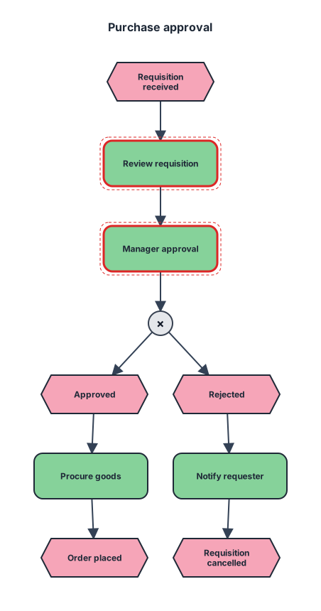
An event-driven process chain for purchase approval from requisition received through manager approval, procurement, and order placed
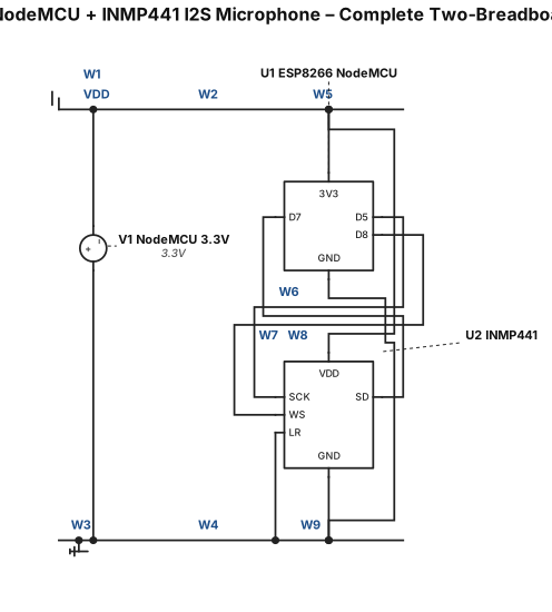
Create a realistic, detailed physical breadboard wiring diagram for an ESP8266 NodeMCU connected to an INMP441 I2S digital MEMS microphone using TWO solderless breadboards placed side-by-side. COMPONENT PLACEMENT: * Breadboard 1: place the ESP8266 NodeMCU across the center gap. * Breadboard 2: place the INMP441 microphone module. * Place both breadboards directly next to each other. * Connect the power and ground rails of both breadboards. * Show realistic jumper wires and clearly labeled pins. * Make the diagram suitable for a beginner to physically reproduce. EXACT INMP441 TO ESP8266 CONNECTIONS: 1. INMP441 VDD → NodeMCU 3.3V 2. INMP441 GND → NodeMCU GND 3. INMP441 SCK → NodeMCU D5 / GPIO14 4. INMP441 WS → NodeMCU D8 / GPIO15 5. INMP441 SD → NodeMCU D7 / GPIO13 6. INMP441 L/R → NodeMCU GND POWER: * Use ONLY the NodeMCU 3.3V output for INMP441 VDD. * Do NOT connect INMP441 VDD to 5V or VIN. * Make one common GND between both breadboards. * Connect the GND rails of both breadboards together. * Connect INMP441 GND and L/R to the common GND rail. LABELS: Clearly label: * NodeMCU 3.3V * NodeMCU GND * D5 / GPIO14 * D8 / GPIO15 * D7 / GPIO13 * INMP441 VDD * INMP441 GND * INMP441 SCK * INMP441 WS * INMP441 SD * INMP441 L/R IMPORTANT: Show the actual physical breadboard holes and jumper-wire connections, not just a symbolic circuit schematic. Use different wire paths so every connection is easy to follow. Do not add any extra components. Title: "ESP8266 NodeMCU + INMP441 I2S Microphone – Complete Two-Brea
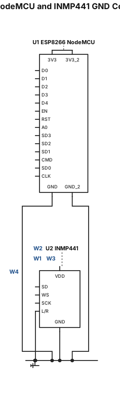
Create a realistic, detailed breadboard wiring diagram showing ONLY the GND connections for an ESP8266 NodeMCU and an INMP441 I2S microphone using TWO solderless breadboards placed side-by-side. Breadboard arrangement: * Breadboard 1 contains the ESP8266 NodeMCU. * Breadboard 2 contains the INMP441 microphone. * Place the two breadboards directly beside each other. * Clearly show the long negative/ground power rail on both breadboards. * Label the negative rail clearly as "GND / –". GND connections: 1. Connect a NodeMCU GND pin to the GND/– rail of Breadboard 1. 2. Connect the GND/– rail of Breadboard 1 to the GND/– rail of Breadboard 2 with a jumper wire. 3. Connect the INMP441 GND pin to the GND/– rail of Breadboard 2. 4. Connect the INMP441 L/R pin to the GND/– rail of Breadboard 2. Show the connections clearly with realistic jumper wires and arrows. Do NOT connect 3.3V, 5V, VDD, SCK, WS, or SD yet. This image must show ONLY the ground connections. Make it a realistic physical breadboard view, NOT a symbolic circuit schematic. Use large clear labels so a beginner can reproduce the connections on a real breadboard.
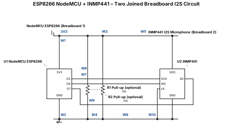
Create a realistic breadboard wiring diagram for an ESP8266 NodeMCU and INMP441 digital MEMS microphone using TWO solderless breadboards placed side-by-side and physically joined together. Components: * 1 × NodeMCU ESP8266 * 1 × INMP441 I2S microphone * 2 × small solderless breadboards * Jumper wires Breadboard arrangement: * Place the two breadboards directly next to each other. * Treat them as one combined working area. * Place the NodeMCU on the first breadboard. * Place the INMP441 module on the second breadboard. * Connect the power rails of both breadboards together using jumper wires. * Connect GND rails of both breadboards together. * Connect the 3.3V rail from the NodeMCU breadboard to the 3.3V rail of the microphone breadboard. * Clearly show that both breadboards share the same common GND. INMP441 → NodeMCU ESP8266: * VDD → 3.3V * GND → GND * SCK → GPIO14 (D5) * WS → GPIO15 (D8) * SD → GPIO13 (D7) * L/R → GND Make the wiring neat, realistic, and easy for a beginner to reproduce on a real breadboard. Use different wire paths so no connections overlap confusingly. Clearly label every pin and wire. Do NOT connect the INMP441 to 5V. Title the diagram: "ESP8266 NodeMCU + INMP441 – Two Joined Breadboard I2S Circuit"